EP1531194A1 - Cathode blocks for aluminium electrolysis cell with wear detection mechanism - Google Patents
Cathode blocks for aluminium electrolysis cell with wear detection mechanism Download PDFInfo
- Publication number
- EP1531194A1 EP1531194A1 EP03026223A EP03026223A EP1531194A1 EP 1531194 A1 EP1531194 A1 EP 1531194A1 EP 03026223 A EP03026223 A EP 03026223A EP 03026223 A EP03026223 A EP 03026223A EP 1531194 A1 EP1531194 A1 EP 1531194A1
- Authority
- EP
- European Patent Office
- Prior art keywords
- holes
- cathode
- block
- cathode blocks
- tracer
- Prior art date
- Legal status (The legal status is an assumption and is not a legal conclusion. Google has not performed a legal analysis and makes no representation as to the accuracy of the status listed.)
- Withdrawn
Links
- 229910052782 aluminium Inorganic materials 0.000 title claims abstract description 31
- 239000004411 aluminium Substances 0.000 title claims abstract description 31
- XAGFODPZIPBFFR-UHFFFAOYSA-N aluminium Chemical compound [Al] XAGFODPZIPBFFR-UHFFFAOYSA-N 0.000 title claims abstract description 31
- 238000005868 electrolysis reaction Methods 0.000 title claims abstract description 27
- 238000001514 detection method Methods 0.000 title claims abstract description 22
- 230000007246 mechanism Effects 0.000 title description 3
- 239000000700 radioactive tracer Substances 0.000 claims abstract description 51
- 239000000463 material Substances 0.000 claims abstract description 41
- 230000003628 erosive effect Effects 0.000 claims abstract description 19
- 238000004458 analytical method Methods 0.000 claims abstract description 7
- 230000000149 penetrating effect Effects 0.000 claims abstract description 4
- OKTJSMMVPCPJKN-UHFFFAOYSA-N Carbon Chemical compound [C] OKTJSMMVPCPJKN-UHFFFAOYSA-N 0.000 claims description 23
- 229910002804 graphite Inorganic materials 0.000 claims description 17
- 239000010439 graphite Substances 0.000 claims description 17
- 238000000034 method Methods 0.000 claims description 10
- 229910052751 metal Inorganic materials 0.000 claims description 7
- 239000002184 metal Substances 0.000 claims description 7
- 229910052797 bismuth Inorganic materials 0.000 claims description 6
- JCXGWMGPZLAOME-UHFFFAOYSA-N bismuth atom Chemical compound [Bi] JCXGWMGPZLAOME-UHFFFAOYSA-N 0.000 claims description 6
- 239000000203 mixture Substances 0.000 claims description 5
- 239000000843 powder Substances 0.000 claims description 5
- 230000000694 effects Effects 0.000 claims description 4
- 239000011888 foil Substances 0.000 claims description 4
- 238000004519 manufacturing process Methods 0.000 claims description 4
- 150000002739 metals Chemical class 0.000 claims description 4
- 238000012544 monitoring process Methods 0.000 claims description 4
- HCHKCACWOHOZIP-UHFFFAOYSA-N Zinc Chemical compound [Zn] HCHKCACWOHOZIP-UHFFFAOYSA-N 0.000 claims description 3
- 239000000126 substance Substances 0.000 claims description 3
- 239000010936 titanium Substances 0.000 claims description 3
- 229910052719 titanium Inorganic materials 0.000 claims description 3
- 229910052725 zinc Inorganic materials 0.000 claims description 3
- 239000011701 zinc Substances 0.000 claims description 3
- RTAQQCXQSZGOHL-UHFFFAOYSA-N Titanium Chemical compound [Ti] RTAQQCXQSZGOHL-UHFFFAOYSA-N 0.000 claims description 2
- 229910045601 alloy Inorganic materials 0.000 claims description 2
- 239000000956 alloy Substances 0.000 claims description 2
- 238000003763 carbonization Methods 0.000 claims description 2
- 238000002372 labelling Methods 0.000 claims description 2
- 150000003839 salts Chemical class 0.000 claims description 2
- 229910052706 scandium Inorganic materials 0.000 claims description 2
- SIXSYDAISGFNSX-UHFFFAOYSA-N scandium atom Chemical compound [Sc] SIXSYDAISGFNSX-UHFFFAOYSA-N 0.000 claims description 2
- 238000007789 sealing Methods 0.000 claims description 2
- 238000005266 casting Methods 0.000 claims 1
- 238000003754 machining Methods 0.000 claims 1
- 238000002354 inductively-coupled plasma atomic emission spectroscopy Methods 0.000 description 10
- 229910000831 Steel Inorganic materials 0.000 description 6
- 239000010959 steel Substances 0.000 description 6
- XEEYBQQBJWHFJM-UHFFFAOYSA-N Iron Chemical compound [Fe] XEEYBQQBJWHFJM-UHFFFAOYSA-N 0.000 description 5
- 229910052799 carbon Inorganic materials 0.000 description 5
- 238000012360 testing method Methods 0.000 description 5
- 238000005553 drilling Methods 0.000 description 4
- 230000008901 benefit Effects 0.000 description 3
- RYGMFSIKBFXOCR-UHFFFAOYSA-N Copper Chemical compound [Cu] RYGMFSIKBFXOCR-UHFFFAOYSA-N 0.000 description 2
- 230000002159 abnormal effect Effects 0.000 description 2
- 229910052729 chemical element Inorganic materials 0.000 description 2
- 239000000571 coke Substances 0.000 description 2
- 239000004020 conductor Substances 0.000 description 2
- 239000000470 constituent Substances 0.000 description 2
- 230000006866 deterioration Effects 0.000 description 2
- 239000003792 electrolyte Substances 0.000 description 2
- 229910052742 iron Inorganic materials 0.000 description 2
- 239000007788 liquid Substances 0.000 description 2
- 239000000314 lubricant Substances 0.000 description 2
- 239000011159 matrix material Substances 0.000 description 2
- 238000002844 melting Methods 0.000 description 2
- 230000008018 melting Effects 0.000 description 2
- 230000007935 neutral effect Effects 0.000 description 2
- 239000006187 pill Substances 0.000 description 2
- 230000002028 premature Effects 0.000 description 2
- 239000000758 substrate Substances 0.000 description 2
- 230000036962 time dependent Effects 0.000 description 2
- 229910000897 Babbitt (metal) Inorganic materials 0.000 description 1
- 229910001369 Brass Inorganic materials 0.000 description 1
- 229910000906 Bronze Inorganic materials 0.000 description 1
- VYZAMTAEIAYCRO-UHFFFAOYSA-N Chromium Chemical compound [Cr] VYZAMTAEIAYCRO-UHFFFAOYSA-N 0.000 description 1
- 229910021591 Copper(I) chloride Inorganic materials 0.000 description 1
- 238000009626 Hall-Héroult process Methods 0.000 description 1
- DGAQECJNVWCQMB-PUAWFVPOSA-M Ilexoside XXIX Chemical compound C[C@@H]1CC[C@@]2(CC[C@@]3(C(=CC[C@H]4[C@]3(CC[C@@H]5[C@@]4(CC[C@@H](C5(C)C)OS(=O)(=O)[O-])C)C)[C@@H]2[C@]1(C)O)C)C(=O)O[C@H]6[C@@H]([C@H]([C@@H]([C@H](O6)CO)O)O)O.[Na+] DGAQECJNVWCQMB-PUAWFVPOSA-M 0.000 description 1
- QCWXUUIWCKQGHC-UHFFFAOYSA-N Zirconium Chemical compound [Zr] QCWXUUIWCKQGHC-UHFFFAOYSA-N 0.000 description 1
- 230000009471 action Effects 0.000 description 1
- 230000002411 adverse Effects 0.000 description 1
- PNEYBMLMFCGWSK-UHFFFAOYSA-N aluminium oxide Inorganic materials [O-2].[O-2].[O-2].[Al+3].[Al+3] PNEYBMLMFCGWSK-UHFFFAOYSA-N 0.000 description 1
- RHZUVFJBSILHOK-UHFFFAOYSA-N anthracen-1-ylmethanolate Chemical compound C1=CC=C2C=C3C(C[O-])=CC=CC3=CC2=C1 RHZUVFJBSILHOK-UHFFFAOYSA-N 0.000 description 1
- 239000003830 anthracite Substances 0.000 description 1
- 229910052790 beryllium Inorganic materials 0.000 description 1
- ATBAMAFKBVZNFJ-UHFFFAOYSA-N beryllium atom Chemical compound [Be] ATBAMAFKBVZNFJ-UHFFFAOYSA-N 0.000 description 1
- 239000010951 brass Substances 0.000 description 1
- 239000010974 bronze Substances 0.000 description 1
- 239000010406 cathode material Substances 0.000 description 1
- 229910052804 chromium Inorganic materials 0.000 description 1
- 239000011651 chromium Substances 0.000 description 1
- 239000011280 coal tar Substances 0.000 description 1
- 229910017052 cobalt Inorganic materials 0.000 description 1
- 239000010941 cobalt Substances 0.000 description 1
- GUTLYIVDDKVIGB-UHFFFAOYSA-N cobalt atom Chemical compound [Co] GUTLYIVDDKVIGB-UHFFFAOYSA-N 0.000 description 1
- 239000011285 coke tar Substances 0.000 description 1
- 229910052802 copper Inorganic materials 0.000 description 1
- 239000010949 copper Substances 0.000 description 1
- KUNSUQLRTQLHQQ-UHFFFAOYSA-N copper tin Chemical compound [Cu].[Sn] KUNSUQLRTQLHQQ-UHFFFAOYSA-N 0.000 description 1
- OXBLHERUFWYNTN-UHFFFAOYSA-M copper(I) chloride Chemical compound [Cu]Cl OXBLHERUFWYNTN-UHFFFAOYSA-M 0.000 description 1
- 230000007797 corrosion Effects 0.000 description 1
- 238000005260 corrosion Methods 0.000 description 1
- 229910001610 cryolite Inorganic materials 0.000 description 1
- 230000001419 dependent effect Effects 0.000 description 1
- 238000007598 dipping method Methods 0.000 description 1
- 230000004064 dysfunction Effects 0.000 description 1
- 238000010348 incorporation Methods 0.000 description 1
- 238000007689 inspection Methods 0.000 description 1
- 230000002687 intercalation Effects 0.000 description 1
- 238000009830 intercalation Methods 0.000 description 1
- 230000003137 locomotive effect Effects 0.000 description 1
- 150000001247 metal acetylides Chemical class 0.000 description 1
- 239000010705 motor oil Substances 0.000 description 1
- 239000012299 nitrogen atmosphere Substances 0.000 description 1
- -1 oxides Chemical class 0.000 description 1
- 230000035515 penetration Effects 0.000 description 1
- 230000008569 process Effects 0.000 description 1
- 230000002250 progressing effect Effects 0.000 description 1
- 230000000135 prohibitive effect Effects 0.000 description 1
- 230000009257 reactivity Effects 0.000 description 1
- 230000009467 reduction Effects 0.000 description 1
- 239000011819 refractory material Substances 0.000 description 1
- 230000008439 repair process Effects 0.000 description 1
- 239000012266 salt solution Substances 0.000 description 1
- 239000010802 sludge Substances 0.000 description 1
- 229910052708 sodium Inorganic materials 0.000 description 1
- 239000011734 sodium Substances 0.000 description 1
- 239000007787 solid Substances 0.000 description 1
- 230000008961 swelling Effects 0.000 description 1
- 238000010998 test method Methods 0.000 description 1
- 230000001988 toxicity Effects 0.000 description 1
- 231100000419 toxicity Toxicity 0.000 description 1
- 229910052726 zirconium Inorganic materials 0.000 description 1
Images
Classifications
-
- C—CHEMISTRY; METALLURGY
- C25—ELECTROLYTIC OR ELECTROPHORETIC PROCESSES; APPARATUS THEREFOR
- C25C—PROCESSES FOR THE ELECTROLYTIC PRODUCTION, RECOVERY OR REFINING OF METALS; APPARATUS THEREFOR
- C25C3/00—Electrolytic production, recovery or refining of metals by electrolysis of melts
- C25C3/06—Electrolytic production, recovery or refining of metals by electrolysis of melts of aluminium
- C25C3/08—Cell construction, e.g. bottoms, walls, cathodes
Definitions
- the invention relates to cathode blocks for aluminium electrolysis cells having a wear detection functionality of by incorporation of tracer materials.
- Aluminium is conventionally produced by the Hall-Heroult process, by the electrolysis of alumina dissolved in cryolite-based molten electrolytes at temperatures up to around 950 °C.
- a Hall-Heroult reduction cell typically has a steel shell provided with an insulating lining of refractory material, which in turn has a lining of carbon contacting the molten constituents.
- Conductor bars connected to the negative pole of a direct current source are embedded in the carbon cathode substrate forming the cell bottom floor.
- the cathode substrate is usually constituted of blocks made of carbon or graphite, joined with a ramming mixture of anthracite, coke, and coal tar.
- a molten aluminium pool acts as the cathode.
- the carbon lining or cathode material has a useful life of four to ten years, or even less under adverse conditions.
- the deterioration of the cathode bottom is due to erosion and penetration of electrolyte and liquid aluminium as well as intercalation of sodium, which causes swelling and deformation of the cathode blocks and ramming mixture.
- the erosion of the cathode block does not occur evenly across the block length but shapes the block surface into a W-profile. Erosion in graphite cathodes may progress at a rate of up to 60 mm per annum. Due to resulting cracks in the cathode blocks, aluminium reaches the steel cathode conductor bars causing corrosion thereof leading to deterioration of the electrical contact, non-uniformity in current distribution and an excessive iron content in the aluminium metal produced.
- a machine condition diagnostic system wherein a distinct tracer element indicator material labels each wearable machine components.
- the lubricant is monitored and periodically or continually sampled to determine the presence of abnormal levels in the amount of indicator material. Since each component or components performing a similar function is labelled with the same indicator, the presence of a particular indicator in abnormal amounts in the lubricant directs the machine operator to the precise location requiring repair or replacement.
- the indicator material is introduced by drilling a bore into the race surface of each bearing in a machine to beyond the depth of maximum acceptable wear, inserting a pill comprised of an indicator material into the bottom of said bore so that each bearing function is represented by a different indicator pill, and sealing said bore.
- Preferred tracer elements for bronze or brass bearings include but are not restricted to aluminium, beryllium, bismuth, carbon, cobalt, chromium and zirconium.
- cathode blocks providing a detection functionality for indicating extent of cathode wear in aluminium electrolysis cells without interrupting the cell operation. Another object of this invention is to provide cathode blocks permitting a detection functionality indicating the wear progression at distinctive locations within the cathode block. It is a further object of this invention to place cathode blocks with wear detection functionality in an electrolysis cell in order to monitor wear progression at distinctive locations throughout the cell.
- the task of the invention is solved by providing a detection functionality for indicating extent of cathode wear in aluminium electrolysis cells without interrupting the cell operation by introduction of tracer materials into the cathode block which are leached out by penetrating aluminium and can be detected by analytical techniques.
- One advantage of this invention is to circumvent the difficulties in implementing direct detection methods usually being based on electrical signals by utilizing standard product quality test methods.
- a standard analytical method utilised in this quality test is Inductively Coupled Plasma Atomic Emission Spectroscopy (ICP-AES).
- ICP-AES Inductively Coupled Plasma Atomic Emission Spectroscopy
- the plasma used in this technique is able to excite many different elements, making ICP-AES a highly effective multi-element detection technique.
- the ICP-AES detection limits vary from 1 to 100 ppb. This technique also provides low detection limits for a lot of high melting elements such as B and Ti.
- ICP-AES as a standard test in aluminium electrolysis cells, can be utilised for the indirect detection of cathode block wear. Tracer materials introduced into the cathode blocks are leached out by penetrating aluminium and can be detected even at very low levels by ICP-AES. Whereas ICP-AES is the preferred analytical technique, various other analytical methods can be employed for the same purpose according to this invention.
- Another advantage of this invention is the accurate pre-warning time it provides to the electrolysis operators to prepare the required shutdown procedures.
- electrolysis cells have either been shut down too early or only after the produced aluminium had already been contaminated with iron from the current collector bars.
- this invention provides means to monitor the wear progression at distinctive locations within the cathode block as well as throughout the electrolysis cell. This option opens the opportunity to decide individually on exchange of cathode blocks or to adjust operational parameters to achieve more homogeneous erosion throughout the electrolysis cell.
- Tracer materials can be placed into the cathode blocks by means of holes.
- the holes can be incorporated in to the cathode block by drilling of the finished block or by introduction of sacrificial material of adequate shape into the raw cathode block prior to carbonisation and graphitisation.
- the hole positions are determined by the preferred tracer materials position. The size of those holes is mostly dependent from the amount of tracer material required for effective detection. It was found that a volume of 15 to 30 cm 3 tracer material has to be inserted in each cathode block to provide enough tracer elements to be detected by ICP-AES under typical production test conditions.
- the tracer material has preferably to be positioned in the region where erosion is the highest. Erosion progresses from the cathode block surface in a non-uniform manner resulting in a so-called W-profile.
- a typical W-profile erosion pattern (3) is indicated progressing from the top of a cathode block (1) down towards the steel-made collector bars (2) at the bottom of this block.
- the best region to position the tracer material is located below the two negative peaks of the W-profile 200 to 500 mm away from both opposing end faces of the block.
- cathode blocks (1) especially of graphite blocks
- the erosion of cathode blocks (1) progresses typically at a rate of 40 mm per annum. It is therefore necessary, as shown in Figure 2, to position the holes (4) for the tracer material just a short distance above the steel-made current collector bars (2) to accurately give 2 to 4 weeks pre-warning time to plan for production shut-down and replacement of the entire electrolysis cell bottom.
- the tracer-filled holes (4) should preferably be 2 to 5 mm deep and have 6 to 20 cm in diameter. This diameter range coincides with the width of the collector bars (2). In practice, the hole diameter will not exceed the width of the collector bar slot, yet a large enough portion of the collector bar surface should be covered for detection.
- the hole diameter ranges from 30 to 100%, most preferably from 70 to 90%, of the slot width.
- This embodiment is not limited to circular holes, any other hole shape can be used in the same manner as described.
- Such prepared cathode blocks are later fitted with collector bars.
- vertical holes (5) can be incorporated in the space between the collector bar slots, their depth exceeding the slot depth by 2 to 5 mm.
- the hole diameter is determined by the web width in between the slots ranging from 30 to 85%, most preferably from 50 to 70%, of the web width.
- Another object of this invention is to insert tracer materials at several distinctive distances from the top block surface thus providing means for a time-dependent monitoring of the erosion progress.
- the tracer materials are positioned at different levels with distances of each 20 to 50 mm starting at 20 to 50 mm below the top block surface.
- different tracer elements can be introduced at various positions inside the cathode blocks to facilitate not only time-dependent monitoring of the erosion progress but also providing the option for discriminating erosion effects at different positions within the cathode blocks.
- the same principle applies to labelling of distinctive cathode blocks by different tracer elements for discrimination of erosion effects at different cathode blocks throughout the entire electrolysis cell.
- This required tracer material volume will be taken up by holes of 0,8 to 1,2 cm diameter.
- the depth of the holes can range from 200 to 500 mm depending mainly on the size of the cathode block and the required position of the tracer material inside the block.
- transversal holes (6) can be positioned either as dead-end holes or as open holes across the entire width of the cathode block. After filling 50 to 90% of the hole volumes with tracer material, the holes are sealed by using ramming paste which is later also used for filling the small seams in between the cathode blocks. Alternatively, graphite plugs can seal the holes.
- horizontal holes (7) are positioned starting from the end face of the cathode block. Such holes need to have a depth of 300 to 500 mm thus covering the entire region where erosion is typically highest. After filling 50 to 90% of hole volumes with tracer material, the holes are sealed by using ramming paste or graphite plugs.
- the tracer elements to be utilised according to this invention can be selected from a wide range of chemical elements, expect for Iron (Fe), which is the main constituent of the steel collector bars.
- This choice includes, but is not limited to, metals starting from atomic number 21 (scandium) up to atomic number 83 (bismuth).
- Preferred are chemical elements that are readily available and are significantly heavier than aluminium in order to provide easy discrimination at ICP-AES analysis.
- the hot aluminium upon contact should preferably easily take up those elements.
- more preferred choices of tracer elements are the metals in the row from atomic number 22 (titanium) to 30 (zinc).
- the chemical composition of the tracer elements is not limited to the pure element. Depending on price, toxicity, chemical reactivity and other factors, the tracer element can be provided in the form of, but is not limited to, salts, oxides, carbides, and alloys. Different tracer materials can also be mixed with each other or with neutral matrix materials before introduction into the cathode block. Neutral matrix materials are graphite or aluminium.
- the physical appearance of the tracer material can vary between, but is not limited to, powders and wires or rods.
- Powders can be fed into the holes and compacted by means of a rod or other devices. Wires or rods are being pushed into the hole.
- the tracer material can be cast into the holes.
- the tracer materials can also be introduced into dead-end holes as a salt solution, thus impregnating the region around the hole end.
- Single collector bar slots of 200 mm width and 150 mm depth were cut out from each block, followed by drilling of two 3 mm deep holes of 10 cm diameter into each slot at a distance of 400 mm from either opposing end faces. Tablets made of pre-compacted powder consisting of 95 w/w% zinc and 5 w/w % copper with dimensions fitting exactly to the holes were placed in each hole. 15 cm diameter pieces of 100 ⁇ m thick flexible graphite foil were fixed on top of each hole as cover. Afterwards, steel collector bars were fitted into the slot. The cathode blocks were placed into an aluminium electrolysis cell.
- Cathode blocks trimmed to their final dimensions were manufactured according to example 1.
- Two parallel collector bar slots of 150 mm width and 150 mm depth each were cut out from each block, followed by drilling of four 152 mm deep holes of 5 cm diameter into the middle of the 100 mm wide web between both slots, whereby one opposing hole pair was positioned at 300 mm and the other at 400 mm away from either opposing end faces.
- Each hole was filled with 25 g of CuCl powder and was then sealed by a graphite rod of 5 cm diameter and 150 mm length. Afterwards, steel collector bars were fitted into the slots.
- the cathode blocks were placed into an aluminium electrolysis cell.
- Cathode blocks trimmed to their final dimensions were manufactured according to example 1.
- 8 pairs of dead-end horizontal holes each of 1 cm diameter were drilled in parallel to the block top face as well as side face starting from the end faces.
- the first 4 holes of opposing hole pairs were drilled at a distance of 25 mm below the top block surface.
- the next pairs each had an axial distance of 50 mm to the respective pair above. All holes were 400 mm deep and the holes of a pair were positioned right and left of he horizontal middle of the block each at a distance of 250 mm from the respective block side face.
Landscapes
- Chemical & Material Sciences (AREA)
- Engineering & Computer Science (AREA)
- Chemical Kinetics & Catalysis (AREA)
- Electrochemistry (AREA)
- Materials Engineering (AREA)
- Metallurgy (AREA)
- Organic Chemistry (AREA)
- Electrolytic Production Of Metals (AREA)
- Investigating And Analyzing Materials By Characteristic Methods (AREA)
- Investigating Or Analysing Materials By Optical Means (AREA)
Abstract
Description
- The invention relates to cathode blocks for aluminium electrolysis cells having a wear detection functionality of by incorporation of tracer materials.
- Aluminium is conventionally produced by the Hall-Heroult process, by the electrolysis of alumina dissolved in cryolite-based molten electrolytes at temperatures up to around 950 °C. A Hall-Heroult reduction cell typically has a steel shell provided with an insulating lining of refractory material, which in turn has a lining of carbon contacting the molten constituents. Conductor bars connected to the negative pole of a direct current source are embedded in the carbon cathode substrate forming the cell bottom floor. The cathode substrate is usually constituted of blocks made of carbon or graphite, joined with a ramming mixture of anthracite, coke, and coal tar.
- In Hall-Heroult cells, a molten aluminium pool acts as the cathode. The carbon lining or cathode material has a useful life of four to ten years, or even less under adverse conditions. The deterioration of the cathode bottom is due to erosion and penetration of electrolyte and liquid aluminium as well as intercalation of sodium, which causes swelling and deformation of the cathode blocks and ramming mixture.
The erosion of the cathode block does not occur evenly across the block length but shapes the block surface into a W-profile. Erosion in graphite cathodes may progress at a rate of up to 60 mm per annum.
Due to resulting cracks in the cathode blocks, aluminium reaches the steel cathode conductor bars causing corrosion thereof leading to deterioration of the electrical contact, non-uniformity in current distribution and an excessive iron content in the aluminium metal produced. - It would therefore be important getting an indication on when the cathode block wear reaches a critical depth to discontinue electrolysis operations early enough for preventing a direct contact between the liquid aluminium and the steel-made electrical contacts. Such detection mechanism should be also accurate enough to prevent as little productivity losses due to electrolysis stop as possible.
Currently practised wear detection tests involve manually dipping a stick of specified length into the hot electrolysis bath until it hits the cathode block surface. Besides being unpleasant, if not dangerous, for the person performing the test, this method is not reliable because in many cases the stick does not reach down to the cathode block surface but rather touches on solid sludge lumps on the block surface, thus implying a cathode wear much lower than actual.
While many methods of wear detection exist, most of them include sensor devices. Such sensors can be costly and, in most cases, an electric circuit is directly involved in the sensing mechanisms. In the case of cathodes for aluminium production, additional costs for sophisticated sensor systems would be commercially prohibitive. Above all, electronic detection systems are also prone to dysfunction due to the high operational temperatures and the strong electrical and magnetic fields in and around the cathode blocks during operation. The electrolysis process is run in a continuous mode leaving no time for dedicated inspection shutdown.
US 6,510,726 describes a method of detecting premature wear of engine bearings in locomotive engine applications by incorporating bismuth as a tracer element into the liner of bearing metal applied to a rigid metal backing of the bearing. A soft metal overlay free of bismuth is applied over the bearing liner and the bearing installed in the engine. The engine oil is periodically tested for the presence of bismuth. Early detection indicates premature wear of the overlay, enabling corrective action to be taken to protect the engine. - In US 4,620,185 a machine condition diagnostic system is described wherein a distinct tracer element indicator material labels each wearable machine components. The lubricant is monitored and periodically or continually sampled to determine the presence of abnormal levels in the amount of indicator material. Since each component or components performing a similar function is labelled with the same indicator, the presence of a particular indicator in abnormal amounts in the lubricant directs the machine operator to the precise location requiring repair or replacement.
The indicator material is introduced by drilling a bore into the race surface of each bearing in a machine to beyond the depth of maximum acceptable wear, inserting a pill comprised of an indicator material into the bottom of said bore so that each bearing function is represented by a different indicator pill, and sealing said bore.
Preferred tracer elements for bronze or brass bearings include but are not restricted to aluminium, beryllium, bismuth, carbon, cobalt, chromium and zirconium. - One object of this invention are cathode blocks providing a detection functionality for indicating extent of cathode wear in aluminium electrolysis cells without interrupting the cell operation. Another object of this invention is to provide cathode blocks permitting a detection functionality indicating the wear progression at distinctive locations within the cathode block. It is a further object of this invention to place cathode blocks with wear detection functionality in an electrolysis cell in order to monitor wear progression at distinctive locations throughout the cell.
- The task of the invention is solved by providing a detection functionality for indicating extent of cathode wear in aluminium electrolysis cells without interrupting the cell operation by introduction of tracer materials into the cathode block which are leached out by penetrating aluminium and can be detected by analytical techniques.
- One advantage of this invention is to circumvent the difficulties in implementing direct detection methods usually being based on electrical signals by utilizing standard product quality test methods.
During operation of the aluminium electrolysis cell, produced aluminium is sampled and the purity checked in periods of about 1,5 days frequency. A standard analytical method utilised in this quality test is Inductively Coupled Plasma Atomic Emission Spectroscopy (ICP-AES). The plasma used in this technique is able to excite many different elements, making ICP-AES a highly effective multi-element detection technique. The ICP-AES detection limits vary from 1 to 100 ppb. This technique also provides low detection limits for a lot of high melting elements such as B and Ti.
ICP-AES, as a standard test in aluminium electrolysis cells, can be utilised for the indirect detection of cathode block wear. Tracer materials introduced into the cathode blocks are leached out by penetrating aluminium and can be detected even at very low levels by ICP-AES. Whereas ICP-AES is the preferred analytical technique, various other analytical methods can be employed for the same purpose according to this invention. - Another advantage of this invention is the accurate pre-warning time it provides to the electrolysis operators to prepare the required shutdown procedures. In the past, electrolysis cells have either been shut down too early or only after the produced aluminium had already been contaminated with iron from the current collector bars.
- The more accurate timing for the shutdown for cathode block replacement results in substantial economic benefits for electrolysis operators.
- Furthermore, this invention provides means to monitor the wear progression at distinctive locations within the cathode block as well as throughout the electrolysis cell. This option opens the opportunity to decide individually on exchange of cathode blocks or to adjust operational parameters to achieve more homogeneous erosion throughout the electrolysis cell.
- Tracer materials can be placed into the cathode blocks by means of holes. The holes can be incorporated in to the cathode block by drilling of the finished block or by introduction of sacrificial material of adequate shape into the raw cathode block prior to carbonisation and graphitisation.
The hole positions are determined by the preferred tracer materials position. The size of those holes is mostly dependent from the amount of tracer material required for effective detection. It was found that a volume of 15 to 30 cm3 tracer material has to be inserted in each cathode block to provide enough tracer elements to be detected by ICP-AES under typical production test conditions. - The invention will now be described by way of examples and with reference to the accompanying drawings in which:
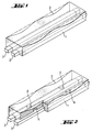
- Figure 1 shows a cathode block with steel-made collector bars and indicates a typical W-profile erosion pattern.
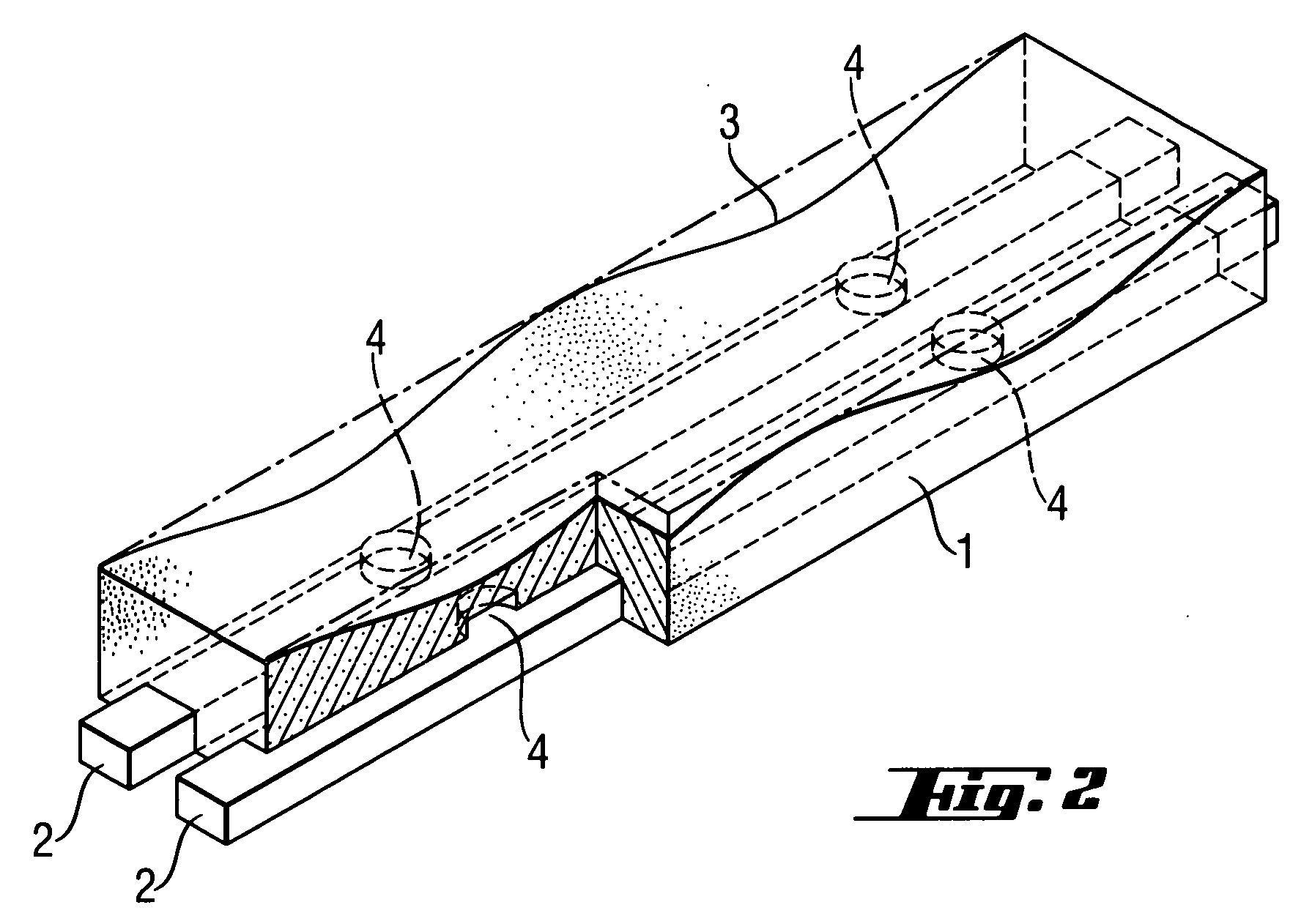
- Figure 2 shows a cathode block having one segment cut out with the tracer-filled vertical holes directly above the collector bars in accordance to this invention. A typical W-profile erosion pattern is indicated.
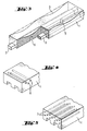
- Figure 3 shows a cathode block having one segment cut out with vertical holes between the collector bars in accordance to this invention. A typical W-profile erosion pattern is indicated
- Figure 4 shows the front part of a cathode block with tracer-filled transversal holes in accordance to this invention.
- Figure 5 shows the front part of a cathode block with tracer-filled horizontal holes in accordance to this invention.
-
- Although all drawings show cathode blocks, or parts thereof, having two collector bar slots, this invention applies to single-slotted cathode blocks in the same manner.
- The tracer material has preferably to be positioned in the region where erosion is the highest. Erosion progresses from the cathode block surface in a non-uniform manner resulting in a so-called W-profile. In Figure 1, a typical W-profile erosion pattern (3) is indicated progressing from the top of a cathode block (1) down towards the steel-made collector bars (2) at the bottom of this block. As can be seen from Fig. 1, the best region to position the tracer material is located below the two negative peaks of the W-profile 200 to 500 mm away from both opposing end faces of the block.
- The erosion of cathode blocks (1), especially of graphite blocks, progresses typically at a rate of 40 mm per annum. It is therefore necessary, as shown in Figure 2, to position the holes (4) for the tracer material just a short distance above the steel-made current collector bars (2) to accurately give 2 to 4 weeks pre-warning time to plan for production shut-down and replacement of the entire electrolysis cell bottom. The tracer-filled holes (4) should preferably be 2 to 5 mm deep and have 6 to 20 cm in diameter. This diameter range coincides with the width of the collector bars (2). In practice, the hole diameter will not exceed the width of the collector bar slot, yet a large enough portion of the collector bar surface should be covered for detection. Hence, the hole diameter ranges from 30 to 100%, most preferably from 70 to 90%, of the slot width. This embodiment is not limited to circular holes, any other hole shape can be used in the same manner as described.
After placing the tracer material into the hole to fill up 70 to 100% of its volume, it can be sealed with a graphite plate, graphite foil or ramming paste. Such prepared cathode blocks are later fitted with collector bars.
In another embodiment of this invention, depicted in Figure 3, vertical holes (5) can be incorporated in the space between the collector bar slots, their depth exceeding the slot depth by 2 to 5 mm. The hole diameter is determined by the web width in between the slots ranging from 30 to 85%, most preferably from 50 to 70%, of the web width.
After placing the tracer material into a hole to fill up 2 to 10% of its volume, it is sealed with a graphite rod or ramming paste. Such prepared cathode blocks are later fitted with collector bars.
In case of cathode designs with a single collector, the vertical holes are positioned at both sides of the collector bar in the same manner. - Another object of this invention is to insert tracer materials at several distinctive distances from the top block surface thus providing means for a time-dependent monitoring of the erosion progress. According to this invention, the tracer materials are positioned at different levels with distances of each 20 to 50 mm starting at 20 to 50 mm below the top block surface.
In another embodiment of this invention, different tracer elements can be introduced at various positions inside the cathode blocks to facilitate not only time-dependent monitoring of the erosion progress but also providing the option for discriminating erosion effects at different positions within the cathode blocks.
The same principle applies to labelling of distinctive cathode blocks by different tracer elements for discrimination of erosion effects at different cathode blocks throughout the entire electrolysis cell. - This required tracer material volume will be taken up by holes of 0,8 to 1,2 cm diameter. The depth of the holes can range from 200 to 500 mm depending mainly on the size of the cathode block and the required position of the tracer material inside the block.
According to this further embodiment, there are two directions to position the holes for the tracer materials in the blocks. As indicated in Figure 4, transversal holes (6) can be positioned either as dead-end holes or as open holes across the entire width of the cathode block. After filling 50 to 90% of the hole volumes with tracer material, the holes are sealed by using ramming paste which is later also used for filling the small seams in between the cathode blocks. Alternatively, graphite plugs can seal the holes. - In another embodiment of this invention, shown in Figure 5, horizontal holes (7) are positioned starting from the end face of the cathode block. Such holes need to have a depth of 300 to 500 mm thus covering the entire region where erosion is typically highest. After filling 50 to 90% of hole volumes with tracer material, the holes are sealed by using ramming paste or graphite plugs.
- Due to the broad detection range of ICP-AES the tracer elements to be utilised according to this invention can be selected from a wide range of chemical elements, expect for Iron (Fe), which is the main constituent of the steel collector bars. This choice includes, but is not limited to, metals starting from atomic number 21 (scandium) up to atomic number 83 (bismuth). Preferred are chemical elements that are readily available and are significantly heavier than aluminium in order to provide easy discrimination at ICP-AES analysis. Furthermore, the hot aluminium upon contact should preferably easily take up those elements. Hence, more preferred choices of tracer elements are the metals in the row from atomic number 22 (titanium) to 30 (zinc).
- The chemical composition of the tracer elements is not limited to the pure element. Depending on price, toxicity, chemical reactivity and other factors, the tracer element can be provided in the form of, but is not limited to, salts, oxides, carbides, and alloys. Different tracer materials can also be mixed with each other or with neutral matrix materials before introduction into the cathode block. Neutral matrix materials are graphite or aluminium.
- The physical appearance of the tracer material can vary between, but is not limited to, powders and wires or rods.
- Powders can be fed into the holes and compacted by means of a rod or other devices. Wires or rods are being pushed into the hole. In case of low melting metals, the tracer material can be cast into the holes. The tracer materials can also be introduced into dead-end holes as a salt solution, thus impregnating the region around the hole end.
- The invention is further described by following examples:
- 100 parts petrol coke with a grain size from 12 µm to 7 mm were mixed with 25 parts pitch at 150 °C in a blade mixer for 10 minutes. The resulting mass was extruded to a blocks of the dimensions 700 x 500 x 3400 mm (width x height x length). These so-called green blocks were placed in a ring furnace, covered by metallurgical coke and heated to 1200 °C under nitrogen atmosphere. The resulting carbonised blocks were then heated to 2800 °C in a lengthwise graphitisation furnace. Afterwards, the raw cathode blocks were trimmed to their final dimensions of 650 x 450 x 3270 mm (width x height x length). Single collector bar slots of 200 mm width and 150 mm depth were cut out from each block, followed by drilling of two 3 mm deep holes of 10 cm diameter into each slot at a distance of 400 mm from either opposing end faces. Tablets made of pre-compacted powder consisting of 95 w/w% zinc and 5 w/w % copper with dimensions fitting exactly to the holes were placed in each hole. 15 cm diameter pieces of 100 µm thick flexible graphite foil were fixed on top of each hole as cover. Afterwards, steel collector bars were fitted into the slot. The cathode blocks were placed into an aluminium electrolysis cell.
- Cathode blocks trimmed to their final dimensions were manufactured according to example 1. Two parallel collector bar slots of 150 mm width and 150 mm depth each were cut out from each block, followed by drilling of four 152 mm deep holes of 5 cm diameter into the middle of the 100 mm wide web between both slots, whereby one opposing hole pair was positioned at 300 mm and the other at 400 mm away from either opposing end faces. Each hole was filled with 25 g of CuCl powder and was then sealed by a graphite rod of 5 cm diameter and 150 mm length. Afterwards, steel collector bars were fitted into the slots. The cathode blocks were placed into an aluminium electrolysis cell.
- Cathode blocks trimmed to their final dimensions were manufactured according to example 1. On either opposing end of the blocks, 8 pairs of dead-end horizontal holes each of 1 cm diameter were drilled in parallel to the block top face as well as side face starting from the end faces. The first 4 holes of opposing hole pairs were drilled at a distance of 25 mm below the top block surface. The next pairs each had an axial distance of 50 mm to the respective pair above. All holes were 400 mm deep and the holes of a pair were positioned right and left of he horizontal middle of the block each at a distance of 250 mm from the respective block side face. After one pre-compacted rod made of 90 parts copper powder and 10 parts graphite powder, having 200 mm length and 1 cm diameter, was introduced into each hole, the holes were sealed by ramming paste. Afterwards, steel collector bars were fitted into the respective slots and the cathode blocks were placed into an aluminium electrolysis cell.
Claims (10)
- Cathode blocks for aluminium electrolysis cells providing a detection functionality for indicating extent of cathode wear in aluminium electrolysis cells without interrupting the cell operation by introduction of tracer materials into the cathode block which are leached out by penetrating aluminium and can be detected by analytical techniques.
- Cathode blocks according to claim 1, having at least 2 holes being positioned above the collector bar slots each at a distance of 200 to 500 mm away from both block end faces, being 2 to 5 mm deep with diameters ranging from 30 to 100% of the slot width, said holes being filled with tracer material from 70 to 100% of its volume, and optionally being sealed by means of graphite plates, graphite foil or ramming paste.
- Cathode blocks according to claim 1, having at least 2 vertical holes being positioned in between the collector bar slots each at a distance of 200 to 500 mm away from both block end faces, being 2 to 5 mm deeper than the slots with diameters ranging from 30 to 85%, most preferably from 50 to 70%, of the web width, said holes being filled with tracer material from 2 to 10% of its volume, and being sealed by means of graphite rods or ramming paste.
- Cathode blocks according to claim 1, having at least 4 vertical holes of 3 to 5 cm diameter being symmetrically positioned on both sides of a single collector bar slot each at a distance of 200 to 500 mm away from both block end faces, being 2 to 5 mm deeper than the slot, said holes being filled with tracer material from 2 to 10% of its volume, and being sealed by means of graphite rods or ramming paste.
- Cathode blocks according to claim 1, providing means for wear progression monitoring having at least 4 dead-end or open-end transversal holes in parallel to the block top face and end faces starting from its side faces or having dead-end horizontal holes in parallel to the block top face and side faces starting from its end faces, each of 0,8 to 1,2 cm diameter, being positioned at different levels at distances between each of 20 to 50 mm starting at 20 to 50 mm below the block top face, their volume being filled with 50 to 90% tracer material and being sealed by ramming paste or graphite plugs.
- Cathode blocks according to claim 5, having tracer materials based on different elements introduced at various positions inside the cathode block, providing the means for discriminating erosion effects at different positions within the cathode blocks.
- Tracer materials according to claims 1 to 6, based on metals starting from atomic number 21 (scandium) to atomic number 83 (bismuth), more preferably based on elements from atomic number 22 (titanium) to 30 (zinc), being provided as pure element, salt, carbide, alloy, or any other suitable chemical composition or mixtures thereof as powder, wire, rod, solution, or any other suitable physical state.
- A method to incorporate holes into cathode blocks according to claims 1 to 6, by machining the finished block with a drill or with a circular saw or by introduction of sacrificial rods of adequate size into the green block prior to carbonisation and graphitisation.
- A method to manufacture cathode blocks according to claims 1 to 6 comprisingincorporating holes into the cathode block according to claim 8,placing tracer material according to claim 7 into the holes by pushing, casting or pouring,sealing the holes with ramming paste or plugs, rods or graphite foil.
- A method for discrimination of erosion effects at different cathode blocks throughout the entire electrolysis cell comprising labelling distinctive cathode blocks according to claims 1 to 5 with different tracer elements and monitoring occurrence of those elements in the produced aluminium by analytical detection methods.
Priority Applications (3)
| Application Number | Priority Date | Filing Date | Title |
|---|---|---|---|
| EP03026223A EP1531194A1 (en) | 2003-11-14 | 2003-11-14 | Cathode blocks for aluminium electrolysis cell with wear detection mechanism |
| JP2004325845A JP4755409B2 (en) | 2003-11-14 | 2004-11-10 | Cathode block for aluminum electrolytic cell with wear detection mechanism |
| BRPI0405016 BRPI0405016A (en) | 2003-11-14 | 2004-11-11 | Aluminum Electrolysis Cell Cathode Blocks With Wear Detection Mechanism |
Applications Claiming Priority (1)
| Application Number | Priority Date | Filing Date | Title |
|---|---|---|---|
| EP03026223A EP1531194A1 (en) | 2003-11-14 | 2003-11-14 | Cathode blocks for aluminium electrolysis cell with wear detection mechanism |
Publications (1)
| Publication Number | Publication Date |
|---|---|
| EP1531194A1 true EP1531194A1 (en) | 2005-05-18 |
Family
ID=34429372
Family Applications (1)
| Application Number | Title | Priority Date | Filing Date |
|---|---|---|---|
| EP03026223A Withdrawn EP1531194A1 (en) | 2003-11-14 | 2003-11-14 | Cathode blocks for aluminium electrolysis cell with wear detection mechanism |
Country Status (3)
| Country | Link |
|---|---|
| EP (1) | EP1531194A1 (en) |
| JP (1) | JP4755409B2 (en) |
| BR (1) | BRPI0405016A (en) |
Cited By (5)
| Publication number | Priority date | Publication date | Assignee | Title |
|---|---|---|---|---|
| RU2294404C1 (en) * | 2005-09-20 | 2007-02-27 | Открытое акционерное общество "Сибирский научно-исследовательский, конструкторский и проектный институт алюминиевой и электродной промышленности" (ОАО "СибВАМИ") | Cathode device of aluminum cell |
| CN101705505B (en) * | 2009-11-18 | 2011-12-07 | 中国铝业股份有限公司 | Cathode carbon block feeding device |
| CN101724857B (en) * | 2008-10-13 | 2013-03-27 | 高德金 | Novel steel bar group of cathode block |
| WO2013068558A3 (en) * | 2011-11-11 | 2013-08-22 | Sgl Carbon Se | Method for measuring surface profiles in working aluminium electrolysis cells |
| CN112986527A (en) * | 2021-01-29 | 2021-06-18 | 山东理工大学 | Method for representing transmission behavior in molten pool in double-roller casting process |
Families Citing this family (2)
| Publication number | Priority date | Publication date | Assignee | Title |
|---|---|---|---|---|
| PL1845174T3 (en) * | 2006-04-13 | 2011-10-31 | Sgl Carbon Se | Cathodes for aluminium electrolysis cell with non-planar slot design |
| CN103820814A (en) * | 2014-03-07 | 2014-05-28 | 新疆生产建设兵团农八师天山铝业有限公司 | Cathode structure composed of carbon block and steel bar |
Citations (3)
| Publication number | Priority date | Publication date | Assignee | Title |
|---|---|---|---|---|
| US3257307A (en) * | 1962-06-11 | 1966-06-21 | Kaiser Aluminium Chem Corp | Electrolytic cell for the production of aluminum |
| US5961811A (en) * | 1997-10-02 | 1999-10-05 | Emec Consultants | Potlining to enhance cell performance in aluminum production |
| EP1344846A1 (en) * | 2002-03-12 | 2003-09-17 | VAW Aluminium-Technologie GmbH | Aluminium reduction cell refractory material and process for the manufacture of carboceramic material |
Family Cites Families (4)
| Publication number | Priority date | Publication date | Assignee | Title |
|---|---|---|---|---|
| CA1277854C (en) * | 1985-05-23 | 1990-12-18 | Alan J. Messenger | Detection of wear |
| FR2789093B1 (en) * | 1999-02-02 | 2001-03-09 | Carbone Savoie | GRAPHITE CATHODE FOR ALUMINUM ELECTROLYSIS |
| JP4195539B2 (en) * | 2000-04-11 | 2008-12-10 | 新日本製鐵株式会社 | Blast furnace bottom water flow detection method |
| JP2002129217A (en) * | 2000-10-30 | 2002-05-09 | Nippon Steel Corp | Method of measuring damage degree of furnace top swivel drive and cage |
-
2003
- 2003-11-14 EP EP03026223A patent/EP1531194A1/en not_active Withdrawn
-
2004
- 2004-11-10 JP JP2004325845A patent/JP4755409B2/en not_active Expired - Fee Related
- 2004-11-11 BR BRPI0405016 patent/BRPI0405016A/en active Search and Examination
Patent Citations (3)
| Publication number | Priority date | Publication date | Assignee | Title |
|---|---|---|---|---|
| US3257307A (en) * | 1962-06-11 | 1966-06-21 | Kaiser Aluminium Chem Corp | Electrolytic cell for the production of aluminum |
| US5961811A (en) * | 1997-10-02 | 1999-10-05 | Emec Consultants | Potlining to enhance cell performance in aluminum production |
| EP1344846A1 (en) * | 2002-03-12 | 2003-09-17 | VAW Aluminium-Technologie GmbH | Aluminium reduction cell refractory material and process for the manufacture of carboceramic material |
Non-Patent Citations (2)
| Title |
|---|
| DATABASE COMPENDEX [online] ENGINEERING INFORMATION, INC., NEW YORK, NY, US; HILTMANN FRANK ET AL: "Laboratory test method for measuring wear rates of carbon cathode materials", XP002284665, Database accession no. E2004128063385 * |
| LIGHT METALS 2003: PROCEEDINGS OF THE TECHNICAL SESSIONS PRESENTED BY THE TMS ALUMINIUM COMMITTEE AT THE 132ND TMS ANNUAL MEETINGS;SAN DIEGO, CA, UNITED STATES MAR 2-6 2003, 2003, TMS Light Met.;TMS Light Metals 2003, pages 655 - 659 * |
Cited By (7)
| Publication number | Priority date | Publication date | Assignee | Title |
|---|---|---|---|---|
| RU2294404C1 (en) * | 2005-09-20 | 2007-02-27 | Открытое акционерное общество "Сибирский научно-исследовательский, конструкторский и проектный институт алюминиевой и электродной промышленности" (ОАО "СибВАМИ") | Cathode device of aluminum cell |
| CN101724857B (en) * | 2008-10-13 | 2013-03-27 | 高德金 | Novel steel bar group of cathode block |
| CN101705505B (en) * | 2009-11-18 | 2011-12-07 | 中国铝业股份有限公司 | Cathode carbon block feeding device |
| WO2013068558A3 (en) * | 2011-11-11 | 2013-08-22 | Sgl Carbon Se | Method for measuring surface profiles in working aluminium electrolysis cells |
| RU2576514C2 (en) * | 2011-11-11 | 2016-03-10 | Сгл Карбон Се | Method to measure surface patterns in operated aluminium electrolysis cells |
| CN112986527A (en) * | 2021-01-29 | 2021-06-18 | 山东理工大学 | Method for representing transmission behavior in molten pool in double-roller casting process |
| CN112986527B (en) * | 2021-01-29 | 2023-10-10 | 山东理工大学 | Method for representing transmission behavior in molten pool in double-roller casting and rolling process |
Also Published As
| Publication number | Publication date |
|---|---|
| JP2005146417A (en) | 2005-06-09 |
| BRPI0405016A (en) | 2005-08-30 |
| JP4755409B2 (en) | 2011-08-24 |
Similar Documents
| Publication | Publication Date | Title |
|---|---|---|
| US6299742B1 (en) | Apparatus for metal extraction | |
| US6231745B1 (en) | Cathode collector bar | |
| US3403090A (en) | Vessel for measuring oxygen content of a molten metal | |
| AU689973B2 (en) | Method and device for measuring the temperature and the level of the molten electrolysis bath cells for aluminium production | |
| CH643885A5 (en) | ELECTRODE ARRANGEMENT OF A MELTFLOW ELECTROLYSIS CELL FOR PRODUCING ALUMINUM. | |
| JP4755409B2 (en) | Cathode block for aluminum electrolytic cell with wear detection mechanism | |
| US4365788A (en) | Process and apparatus for determining the level of molten metal in a metallurgical vessel, the temperature of the molten metal and the extent of wear of the refractory lining of the vessel | |
| FR2600450A1 (en) | METHOD FOR INDIVIDUALLY MARKING PRECISE ANODES FOR ELECTROLYTIC PRODUCTION OF ALUMINUM | |
| US3629079A (en) | Alumina feed control | |
| CN1226612A (en) | Molten salt electrolytic cells for producing rare-earth metals and alloys | |
| Yaroshevskyi et al. | Characterization of a Recyclate‐Based MgO‐Steel Composite as‐Sintered Inert Anode Candidate after Exposure to Cryolite Electrolysis | |
| Adamczyk et al. | Corrosion and Process Analysis of a Preoxidized MgO Recyclate‐Based Cermet Anode in Laboratory‐Scale Na‐Cryolite Molten Salt Electrolysis of Aluminum at 1000° C | |
| RU2727441C1 (en) | Cathode block with slot of special geometrical shape | |
| Zoukel et al. | Study of aluminum carbide formation in Hall-Heroult electrolytic cells | |
| Patel et al. | Influence of internal cathode structure on behavior during electrolysis part III: Wear behavior in graphitic materials | |
| EP4266010A1 (en) | Actuator for a probe | |
| EP4266011A1 (en) | Measurement system for an aluminum reduction cell and method for measuring electrolyte height and/or metal height in an aluminum reduction cell | |
| Solli et al. | Design and performance of a laboratory cell for determination of current efficiency in the electrowinning of aluminium | |
| WO2014003571A1 (en) | Electrode and a method for making same | |
| US3766025A (en) | Repairing electrolytic cells | |
| EP2776610B1 (en) | Method for measuring surface profiles in working aluminium electrolysis cells | |
| MXPA04008886A (en) | Minimising carbon transfer in an electrolytic cell. | |
| SU624137A1 (en) | Sampler for extracting medium from melt | |
| US1531528A (en) | Gauging depths in an electrolytic cell | |
| Padamata | Electrolysis of cryolite-alumina melts and suspensions with oxygen evolving electrodes |
Legal Events
| Date | Code | Title | Description |
|---|---|---|---|
| PUAI | Public reference made under article 153(3) epc to a published international application that has entered the european phase |
Free format text: ORIGINAL CODE: 0009012 |
|
| AK | Designated contracting states |
Kind code of ref document: A1 Designated state(s): AT BE BG CH CY CZ DE DK EE ES FI FR GB GR HU IE IT LI LU MC NL PT RO SE SI SK TR |
|
| AX | Request for extension of the european patent |
Extension state: AL LT LV MK |
|
| 17P | Request for examination filed |
Effective date: 20051118 |
|
| AKX | Designation fees paid |
Designated state(s): AT BE BG CH CY CZ DE DK EE ES FI FR GB GR HU IE IT LI LU MC NL PT RO SE SI SK TR |
|
| 17Q | First examination report despatched |
Effective date: 20070330 |
|
| RAP1 | Party data changed (applicant data changed or rights of an application transferred) |
Owner name: SGL CARBON SE |
|
| RAP1 | Party data changed (applicant data changed or rights of an application transferred) |
Owner name: SGL CARBON SE |
|
| STAA | Information on the status of an ep patent application or granted ep patent |
Free format text: STATUS: THE APPLICATION IS DEEMED TO BE WITHDRAWN |
|
| 18D | Application deemed to be withdrawn |
Effective date: 20130601 |