EP1531081A2 - Headrest apparatus - Google Patents
Headrest apparatus Download PDFInfo
- Publication number
- EP1531081A2 EP1531081A2 EP04024627A EP04024627A EP1531081A2 EP 1531081 A2 EP1531081 A2 EP 1531081A2 EP 04024627 A EP04024627 A EP 04024627A EP 04024627 A EP04024627 A EP 04024627A EP 1531081 A2 EP1531081 A2 EP 1531081A2
- Authority
- EP
- European Patent Office
- Prior art keywords
- headrest
- backrest frame
- guide
- support
- guide bracket
- Prior art date
- Legal status (The legal status is an assumption and is not a legal conclusion. Google has not performed a legal analysis and makes no representation as to the accuracy of the status listed.)
- Withdrawn
Links
Images


Classifications
-
- B—PERFORMING OPERATIONS; TRANSPORTING
- B60—VEHICLES IN GENERAL
- B60N—SEATS SPECIALLY ADAPTED FOR VEHICLES; VEHICLE PASSENGER ACCOMMODATION NOT OTHERWISE PROVIDED FOR
- B60N2/00—Seats specially adapted for vehicles; Arrangement or mounting of seats in vehicles
- B60N2/80—Head-rests
- B60N2/806—Head-rests movable or adjustable
- B60N2/838—Tiltable
- B60N2/841—Tiltable characterised by their locking devices
- B60N2/85—Tiltable characterised by their locking devices with continuous positioning
-
- B—PERFORMING OPERATIONS; TRANSPORTING
- B60—VEHICLES IN GENERAL
- B60N—SEATS SPECIALLY ADAPTED FOR VEHICLES; VEHICLE PASSENGER ACCOMMODATION NOT OTHERWISE PROVIDED FOR
- B60N2/00—Seats specially adapted for vehicles; Arrangement or mounting of seats in vehicles
- B60N2/80—Head-rests
- B60N2/806—Head-rests movable or adjustable
- B60N2/838—Tiltable
- B60N2/856—Tiltable movable to an inoperative or stowed position
Definitions
- the present invention relates to a headrest apparatus for automobile, and more particularly to a headrest apparatus that can be folded easily without being detached from a seat.
- a headrest apparatus for automobile is used to support heads of passengers to protect them from wounds by accidents.
- a conventional headrest apparatus is provided at an upper part of a seat and the height thereof is adjustable in an up-and-down direction.
- a rotation radius from a rotation axis of the seat to an upper end of the headrest apparatus is too long.
- a user should detach the headrest apparatus to fold the seat in a frontward or a backward direction, which brings a inconvenience to the user.
- the present invention provides a convenient headrest apparatus for automobile that can be folded easily without being detached from the seat.
- a headrest apparatus comprising: a headrest; a headrest support to support the headrest; a backrest frame to form a backrest of a seat; a guide bracket connecting the headrest support to the backrest frame and comprising a guide part to guide a relative rotation of the headrest support to the backrest frame and a rotation restricting part to restrict the relative rotation of the headrest support to the backrest frame; and a hinge shaft to rotatably connect the backrest frame to the guide bracket.
- the rotation restricting part comprises a stopping hole grooved from a circumferential side of the guide part and a stopping protrusion to form a predetermined angle with respect to the stopping hole and to protrude from another circumferential side of the guide part.
- the headrest apparatus further comprises a spring to elastically bias the backrest frame with respect to the guide bracket.
- the headrest apparatus further comprises a bush that is provided in the backrest frame and through which the hinge shaft passes to slidably connect the backrest frame to the hinge shaft.
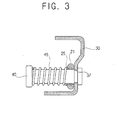
- a headrest apparatus 7 for automobile comprises a headrest 10, a headrest support 15 to support the headrest 10, a backrest frame 20 to form a backrest of a seat, a guide bracket 30 to connect the headrest support 15 to the backrest frame 20 and to guide and restrict a rotation of the headrest support 15 and the backrest frame 20 about each other and a hinge shaft 40 to rotatably connect the backrest frame 20 to the guide bracket 30.
- the headrest 10 is provided at an upper part of the backrest of the seat and supported by the headrest support 15.
- the headrest support 15 is of an approximately reverse U shape and has opposite ends each connected to the guide bracket 30.
- the headrest support 15 may be securely connected to the guide bracket 30 by a welding, a rivet, a bolt and the like.
- the backrest frame 20 is of an approximately reverse U shape and comprises a pair of bracket connecting parts 21 protruding toward each of ends of the headrest support 15 at an upper part thereof.
- the bracket connecting parts 21 of the backrest frame 20 are rotatably connected to the hinge shaft 40 and formed with through holes (not shown) through which the hinge shaft 40 passes.
- a bush of a ring shape is inserted in the each of the through holes of bracket connecting parts 21 through which the hinge shaft 40 passes to slidably connect the backrest frame 20 to the hinge shaft 40.
- the bush 25 may be a metal bearing, which prolongs a length of lives of the backrest frame 20 and the hinge shaft 40.
- the pair of guide brackets 30 is positioned at opposite sides of the headrest support 15 and the backrest frame 20 and each of the pair of the guide bracket 30 faces each other.
- the guide bracket 30 comprises a guide part 31 to guide the relative rotation of the headrest support 15 to the backrest frame 20 and a rotation restricting part to restrict the relative rotation of the headrest support 15 to the backrest frame 20.
- the guide part 31 is provided along a direction of the relative rotation of the headrest support 15 to the backrest frame 20, i.e., a folded direction of the headrest 10 on the backrest frame 20.
- the guide part 31 contacts to a side of the backrest frame 20 to guide the rotation of the headrest support 15 with respect to the backrest frame 20 during a folding process of the headrest 10 on the backrest frame 20.
- the rotation restricting part to restrict the relative rotation of the headrest support 15 to the backrest frame 20 comprises a stopping hole 33 grooved from a circumferential side of the guide part 31 and a stopping protrusion 35 to protrude from another circumferential side thereof.
- the bracket connecting part 21 of the backrest frame 20 which restricts an upward movement of the guide bracket 30.
- the bracket connecting part 21 of the backrest frame 20 is inserted in the stopping hole 33 of the guide bracket 30.
- the headrest support 15 keeps not to be folded with respect to the backrest frame 20, i.e., the headrest 10 keeps not to be folded with respect to the backrest frame 20 of the seat.
- the stopping protrusion 35 of the guide bracket 30 contacts to the bracket connecting part 21 of the backrest frame 20, which restricts a downward movement of the guide bracket 30.
- the bracket connecting part 21 of the backrest frame 20 contacts to the stopping protrusion 35 of the guide bracket 30.
- the headrest support 15 is positioned at a predetermined angle with the backrest frame 20, so that the headrest 10 keeps to be folded with respect to the backrest frame 20.
- a hinge connecting hole 37 to insert an end of the hinge shaft 40.
- the bush 25 inserted in the through hole 37 of the bracket connecting part 21 is rotatably connected to the hinge shaft 40.
- a spring to elastically bias the backrest frame 20 with respect to the guide bracket 30.
- the backrest frame 20 and the guide bracket 30 closely contact to each other by the spring 45, which prevents the guide bracket 30 from being separated from the backrest frame 20.
- the headrest 10 keeps to be stably positioned.
- the bracket connecting part 21 of the backrest frame 20 is inserted in the stopping hole 33 of the guide bracket 30 as shown in FIG. 1.
- the headrest support 15 When the headrest 10 is to be folded, the headrest support 15 is moved in a right direction of the hinge shaft 40 of the headrest support 15, so that the bracket connecting part 21 of the backrest frame 20 inserted in the stopping hole 33 of the guide bracket 30 is released from the stopping hole 33.
- the guide bracket 30 released from the bracket connecting part 21 of the backrest frame 20 is moved downwardly, i.e., in the direction of the arrow shown in FIG. 4.
- the guide part 31 of the guide bracket 30 slides on the bracket connecting part 21 of the backrest frame 20 and moves forewardly.
- the stopping protrusion 35 of the guide bracket 30 contacts to the bracket connecting part 21 of the backrest frame 20.
- the bracket connecting part 21 of the backrest frame 20 closely contacts to the stopping protrusion 35 and the guide part 31 of the guide bracket 30 by the spring 45, so that the guide bracket 30 doesn't separate from the backrest frame 20.
- the headrest support 15 securely connected to the guide bracket 30 is positioned at a predetermined angle with the backrest frame 20, so that the headrest 10 keeps to be folded with respect to the backrest frame 20 of the seat.
- the present invention provides a guide bracket to connect the headrest support to the backrest frame and to guide and restrict a relative rotation of the headrest support to the backrest frame and the backrest frame is rotatably connected to the guide bracket, so that the headrest can be easily folded without being detached from the seat.
- the backrest frame is of an approximately U shape, but not limited thereto. That is, shapes of the backrest frame may be varied as required.
- the present invention provides the headrest apparatus for automobile that can be folded easily without being detached from the seat.
Landscapes
- Engineering & Computer Science (AREA)
- Aviation & Aerospace Engineering (AREA)
- Transportation (AREA)
- Mechanical Engineering (AREA)
- Seats For Vehicles (AREA)
- Chair Legs, Seat Parts, And Backrests (AREA)
Abstract
Description
Claims (4)
- A headrest apparatus comprising:a headrest;a headrest support to support the headrest;a backrest frame to form a backrest of a seat;a guide bracket connecting the headrest support to the backrest frame and comprising a guide part to guide a relative rotation of the headrest support to the backrest frame and a rotation restricting part to restrict the relative rotation of the headrest support to the backrest frame; anda hinge shaft to rotatably connect the backrest frame to the guide bracket.
- The headrest apparatus according to claim 1, wherein the rotation restricting part comprises a stopping hole grooved from a circumferential side of the guide part and a stopping protrusion to form a predetermined angle with respect to the stopping hole and to protrude from another circumferential side of the guide part.
- The headrest apparatus according to claim 2, further comprising a spring to elastically bias the backrest frame with respect to the guide bracket.
- The headrest apparatus according to claim 3, further comprising a bush that is provided in the backrest frame and through which the hinge shaft passes to slidably connect the backrest frame to the hinge shaft
Applications Claiming Priority (2)
| Application Number | Priority Date | Filing Date | Title |
|---|---|---|---|
| KR2003080071 | 2003-11-13 | ||
| KR10-2003-0080071A KR100525638B1 (en) | 2003-11-13 | 2003-11-13 | Head rest apparatus for automobile |
Publications (2)
| Publication Number | Publication Date |
|---|---|
| EP1531081A2 true EP1531081A2 (en) | 2005-05-18 |
| EP1531081A3 EP1531081A3 (en) | 2007-01-17 |
Family
ID=34431763
Family Applications (1)
| Application Number | Title | Priority Date | Filing Date |
|---|---|---|---|
| EP04024627A Withdrawn EP1531081A3 (en) | 2003-11-13 | 2004-10-15 | Headrest apparatus |
Country Status (2)
| Country | Link |
|---|---|
| EP (1) | EP1531081A3 (en) |
| KR (1) | KR100525638B1 (en) |
Cited By (1)
| Publication number | Priority date | Publication date | Assignee | Title |
|---|---|---|---|---|
| CN110091779A (en) * | 2019-06-05 | 2019-08-06 | 常州工程职业技术学院 | A kind of automobile chair frame structure |
Families Citing this family (1)
| Publication number | Priority date | Publication date | Assignee | Title |
|---|---|---|---|---|
| KR102083173B1 (en) * | 2013-12-02 | 2020-03-02 | 주식회사 다스 | Folding headrest for vehicle |
Family Cites Families (3)
| Publication number | Priority date | Publication date | Assignee | Title |
|---|---|---|---|---|
| FR1562595A (en) * | 1967-05-03 | 1969-04-04 | ||
| DE4421825C2 (en) * | 1994-06-22 | 1998-07-16 | Keiper Recaro Gmbh Co | Head restraints for vehicle seats, in particular for motor vehicle rear seats |
| JP3758275B2 (en) * | 1997-02-25 | 2006-03-22 | アイシン精機株式会社 | Vehicle headrest device |
-
2003
- 2003-11-13 KR KR10-2003-0080071A patent/KR100525638B1/en not_active Expired - Fee Related
-
2004
- 2004-10-15 EP EP04024627A patent/EP1531081A3/en not_active Withdrawn
Cited By (1)
| Publication number | Priority date | Publication date | Assignee | Title |
|---|---|---|---|---|
| CN110091779A (en) * | 2019-06-05 | 2019-08-06 | 常州工程职业技术学院 | A kind of automobile chair frame structure |
Also Published As
| Publication number | Publication date |
|---|---|
| EP1531081A3 (en) | 2007-01-17 |
| KR100525638B1 (en) | 2005-11-03 |
| KR20050046085A (en) | 2005-05-18 |
Similar Documents
| Publication | Publication Date | Title |
|---|---|---|
| US6076233A (en) | Grab rail and hook assembly for a vehicle | |
| US7789265B2 (en) | Tab structure for controlling cups in vehicles | |
| US6074010A (en) | Headrest apparatus for vehicle seat | |
| US7520482B2 (en) | Cup holder for vehicles | |
| GB2433879A (en) | Seat back frame for automotive seat | |
| JP2006528111A5 (en) | ||
| CA2176426C (en) | Seat track apparatus | |
| JP2003040021A (en) | Folding cup holder | |
| EP1531081A2 (en) | Headrest apparatus | |
| US20040233557A1 (en) | Breakaway exterior rearview mirror assembly | |
| JP5184258B2 (en) | Hinge structure of vehicle board | |
| JPH0350039A (en) | Cup holder for vehicle | |
| JP2794389B2 (en) | Vehicle cup holder | |
| CN212447802U (en) | Automobile, electric tailgate and swing arm device | |
| JP5975485B2 (en) | Pantograph jack for automobile | |
| JPH08112160A (en) | Vehicle seat back frame structure | |
| JP2000354537A (en) | Hanging hook device | |
| KR100432006B1 (en) | Cup holder for an vehicle | |
| JPS6325227Y2 (en) | ||
| KR20250064470A (en) | Clip for fixing interior part of vehicle | |
| JP4834204B2 (en) | Seat back frame | |
| JP2819095B2 (en) | Automotive cup holder | |
| KR100368376B1 (en) | A Multiple-Stage Cupholder | |
| JP2026070765A (en) | wheelchair | |
| JP3479959B2 (en) | Seat support device |
Legal Events
| Date | Code | Title | Description |
|---|---|---|---|
| PUAI | Public reference made under article 153(3) epc to a published international application that has entered the european phase |
Free format text: ORIGINAL CODE: 0009012 |
|
| AK | Designated contracting states |
Kind code of ref document: A2 Designated state(s): AT BE BG CH CY CZ DE DK EE ES FI FR GB GR HU IE IT LI LU MC NL PL PT RO SE SI SK TR |
|
| AX | Request for extension of the european patent |
Extension state: AL HR LT LV MK |
|
| PUAL | Search report despatched |
Free format text: ORIGINAL CODE: 0009013 |
|
| AK | Designated contracting states |
Kind code of ref document: A3 Designated state(s): AT BE BG CH CY CZ DE DK EE ES FI FR GB GR HU IE IT LI LU MC NL PL PT RO SE SI SK TR |
|
| AX | Request for extension of the european patent |
Extension state: AL HR LT LV MK |
|
| 17P | Request for examination filed |
Effective date: 20070716 |
|
| AKX | Designation fees paid |
Designated state(s): DE FR TR |
|
| 17Q | First examination report despatched |
Effective date: 20071109 |
|
| STAA | Information on the status of an ep patent application or granted ep patent |
Free format text: STATUS: THE APPLICATION IS DEEMED TO BE WITHDRAWN |
|
| 18D | Application deemed to be withdrawn |
Effective date: 20100723 |