EP1531079A2 - Seat sliding device - Google Patents
Seat sliding device Download PDFInfo
- Publication number
- EP1531079A2 EP1531079A2 EP04026229A EP04026229A EP1531079A2 EP 1531079 A2 EP1531079 A2 EP 1531079A2 EP 04026229 A EP04026229 A EP 04026229A EP 04026229 A EP04026229 A EP 04026229A EP 1531079 A2 EP1531079 A2 EP 1531079A2
- Authority
- EP
- European Patent Office
- Prior art keywords
- seat
- memory
- rail
- link
- sliding device
- Prior art date
- Legal status (The legal status is an assumption and is not a legal conclusion. Google has not performed a legal analysis and makes no representation as to the accuracy of the status listed.)
- Withdrawn
Links
- 230000004044 response Effects 0.000 claims description 7
- 210000000078 claw Anatomy 0.000 description 13
- 238000013459 approach Methods 0.000 description 1
- 230000006866 deterioration Effects 0.000 description 1
- 230000002708 enhancing effect Effects 0.000 description 1
- 238000004519 manufacturing process Methods 0.000 description 1
- 230000002093 peripheral effect Effects 0.000 description 1
Images


Classifications
-
- B—PERFORMING OPERATIONS; TRANSPORTING
- B60—VEHICLES IN GENERAL
- B60N—SEATS SPECIALLY ADAPTED FOR VEHICLES; VEHICLE PASSENGER ACCOMMODATION NOT OTHERWISE PROVIDED FOR
- B60N2/00—Seats specially adapted for vehicles; Arrangement or mounting of seats in vehicles
- B60N2/02—Seats specially adapted for vehicles; Arrangement or mounting of seats in vehicles the seat or part thereof being movable, e.g. adjustable
- B60N2/04—Seats specially adapted for vehicles; Arrangement or mounting of seats in vehicles the seat or part thereof being movable, e.g. adjustable the whole seat being movable
- B60N2/06—Seats specially adapted for vehicles; Arrangement or mounting of seats in vehicles the seat or part thereof being movable, e.g. adjustable the whole seat being movable slidable
- B60N2/07—Slide construction
- B60N2/0702—Slide construction characterised by its cross-section
- B60N2/0715—C or U-shaped
-
- B—PERFORMING OPERATIONS; TRANSPORTING
- B60—VEHICLES IN GENERAL
- B60N—SEATS SPECIALLY ADAPTED FOR VEHICLES; VEHICLE PASSENGER ACCOMMODATION NOT OTHERWISE PROVIDED FOR
- B60N2/00—Seats specially adapted for vehicles; Arrangement or mounting of seats in vehicles
- B60N2/02—Seats specially adapted for vehicles; Arrangement or mounting of seats in vehicles the seat or part thereof being movable, e.g. adjustable
- B60N2/04—Seats specially adapted for vehicles; Arrangement or mounting of seats in vehicles the seat or part thereof being movable, e.g. adjustable the whole seat being movable
- B60N2/06—Seats specially adapted for vehicles; Arrangement or mounting of seats in vehicles the seat or part thereof being movable, e.g. adjustable the whole seat being movable slidable
- B60N2/07—Slide construction
- B60N2/0702—Slide construction characterised by its cross-section
- B60N2/0705—Slide construction characterised by its cross-section omega-shaped
-
- B—PERFORMING OPERATIONS; TRANSPORTING
- B60—VEHICLES IN GENERAL
- B60N—SEATS SPECIALLY ADAPTED FOR VEHICLES; VEHICLE PASSENGER ACCOMMODATION NOT OTHERWISE PROVIDED FOR
- B60N2/00—Seats specially adapted for vehicles; Arrangement or mounting of seats in vehicles
- B60N2/02—Seats specially adapted for vehicles; Arrangement or mounting of seats in vehicles the seat or part thereof being movable, e.g. adjustable
- B60N2/04—Seats specially adapted for vehicles; Arrangement or mounting of seats in vehicles the seat or part thereof being movable, e.g. adjustable the whole seat being movable
- B60N2/06—Seats specially adapted for vehicles; Arrangement or mounting of seats in vehicles the seat or part thereof being movable, e.g. adjustable the whole seat being movable slidable
- B60N2/08—Seats specially adapted for vehicles; Arrangement or mounting of seats in vehicles the seat or part thereof being movable, e.g. adjustable the whole seat being movable slidable characterised by the locking device
- B60N2/0812—Location of the latch
- B60N2/0825—Location of the latch outside the rail
-
- B—PERFORMING OPERATIONS; TRANSPORTING
- B60—VEHICLES IN GENERAL
- B60N—SEATS SPECIALLY ADAPTED FOR VEHICLES; VEHICLE PASSENGER ACCOMMODATION NOT OTHERWISE PROVIDED FOR
- B60N2/00—Seats specially adapted for vehicles; Arrangement or mounting of seats in vehicles
- B60N2/02—Seats specially adapted for vehicles; Arrangement or mounting of seats in vehicles the seat or part thereof being movable, e.g. adjustable
- B60N2/04—Seats specially adapted for vehicles; Arrangement or mounting of seats in vehicles the seat or part thereof being movable, e.g. adjustable the whole seat being movable
- B60N2/06—Seats specially adapted for vehicles; Arrangement or mounting of seats in vehicles the seat or part thereof being movable, e.g. adjustable the whole seat being movable slidable
- B60N2/08—Seats specially adapted for vehicles; Arrangement or mounting of seats in vehicles the seat or part thereof being movable, e.g. adjustable the whole seat being movable slidable characterised by the locking device
- B60N2/0831—Movement of the latch
- B60N2/0862—Movement of the latch sliding
- B60N2/0875—Movement of the latch sliding in a vertical direction
Definitions
- This invention generally relates to a vehicle seat sliding device capable of adjusting an axial directional position of a vehicle seat. More particularly, this invention pertains to a vehicle seat sliding device having a so-called walk-in mechanism for moving a vehicle seat from an occupant's seated position to a forefront seat position, thereby enhancing a getting on and off for an occupant at a back seat.
- the vehicle seat sliding device is configured with a memorizing mechanism for returning the vehicle seat already having moved to the forefront position to the occupant's seated position set before the walk-in operation.
- JP No. 11(1999)-334431A discloses a seat sliding device having a seat sliding main body, a locking mechanism and a memorizing mechanism.
- the seat sliding main body is configured with a lower rail fixed at a vehicle floor and extending in a seat longitudinal direction and an upper rail fixed at a seat and slidably guided by the lower rail.
- the memorizing mechanism includes a memory slide, which is attached at the lower rail and can be switched between a slidable movement along the lower rail and a fixed condition thereto.
- the locking mechanism is attached at the upper rail and establishes a locked or unlocked condition between the upper rail and the lower rail. A cooperation of the locking mechanism and the memorizing mechanism enables a seat return from a seat position set after a seat walk-in movement to an occupant's seated position set before the seat walk-in movement.
- each of the locking mechanism and the memorizing mechanism has been attached at an outer surface of the seat sliding main body. Therefore, an area for placing each mechanism at the seat sliding main body is constrained. Further, the number of components for the cooperation thereof may be increased, thereby causing a high manufacturing cost. Still further, the above-described structure may increase a lateral dimension of the seat sliding device, thereby narrowing a below space for an occupant to be seated at a rear seat
- the lower rail is required to have an engaging hole for engaging the memory slide at the lower rail. This structure may deteriorate rigidity of the lower rail.
- a seat sliding device including a lower rail fixed at a stationary part and extending in a seat longitudinal direction, an upper rail fixed at a seat and slidably guided by the lower rail, a lock mechanism for locking and unlocking a slidable movement of the upper rail to the lower rail in order to adjust a position of the seat relative to the stationary part, the lock mechanism being attached at the upper rail, and a memory mechanism for returning the seat, which has moved to a forefront seat position from an occupant's seated position during a walk-in operation, to the occupant's seated position characterized in that the memory mechanism having a memory rail positioned at a distance from at least one of the lower rail and the upper rail and a memory slide configured to be fixed to the memory rail and to be slidably movable relative to the memory rail.
- the memory slide is configured separately from the seat sliding main body. Therefore, the memory slide can be disposed in a space between the seat and the seat sliding device. Further, the lateral dimension of the seat sliding device can be narrowed without narrowing the below space of the occupant to be seated at the rear seat. Still further, the lower rail is not required to have an engaging hole for engaging the memory slide, thereby not causing the deterioration of rigidity of the lower rail.
- the memory mechanism includes a first link for releasing an engagement between the memory slide with the memory rail in association with adjustment of the seat position, a second link for releasing the lock mechanism from locking the slidable movement of the upper rail to the lower rail in response to a forward inclination of a seat back, and a hold link for holding the second link at a releasing position for releasing the lock mechanism for the walk-in operation of the seat and for holding the second link at a position for operating the lock mechanism along with the memory slide when the seat is returned to the occupant's seated position.
- the first link, the second link and the hold link are positioned above at least one of the lower rail and the upper rail.
- the lock mechanism and the memory mechanism are positioned above the seat sliding main body, thereby operating the lock mechanism in conjunction with the memory mechanism, vice versa, with a fewer components and assuring the below space of the occupant seated at the rear seat.
- Fig. 1 is an exploded perspective view illustrating a seat sliding device according to an embodiment of the present invention
- Fig. 2 is an exploded perspective view illustrating a seat sliding main body of the seat sliding device according to the embodiment of the present invention
- Fig. 3 is a partially enlarged view illustrating a mechanism of the seat sliding device according to the embodiment of the present invention.
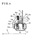
- Fig. 4 is a sectional view taken along a line A-A in Fig. 3;
- Fig. 5 is the other partially enlarged view illustrating the mechanism of the seat sliding device according to the embodiment of the present invention.
- Fig. 6 is a sectional view taken along a line B-B in Fig. 5;
- Fig. 7 is a side view illustrating a seat provided with the seat sliding device according to the embodiment of the present invention.
- a seat-sliding device 2 is provided with a seat sliding main body 20 having a lower rail 21 and an upper rail 31.
- the lower rail 21 is fixed at a vehicle floor 9 (shown in Fig. 7, i.e., stationary part) via a front bracket 22 and a rear bracket 23.
- the upper rail 31 is fixed at a seat 10 (shown in Fig. 9) and is slidably guided by the lower rail 21.
- Each lower and upper rail 21 and 31 extends in a seat longitudinal direction having a constant cross sectional shape in a seat lateral direction.
- At least one bearing 39 is disposed between the lower rail 21 and the upper rail 31 in order to smooth a sliding movement therebetween.
- the seat-sliding device 2 can have a pair of each component. Following explanation will rely upon the single structure of each component for simplifying the description.
- a lower arm 14 is fixed at an upper surface of the upper rail 31 and is positioned at either center, left or right side of the seat 10, thereby supporting a seat cushion 11 on the upper rail 31.
- a reclining device 16 is provided at a rear end portion of the lower arm 14 to adjust a reclining angle of a seat back 12 relative to the seat cushion 11.
- An upper arm 15 fixed at the reclining device 16 supports the reclined seat back 12.
- the seat sliding main body 20 houses a lock mechanism 30 for locking and unlocking a slidable movement of the upper rail 31 relative to the lower rail 21.
- the upper rail 31 has a reverse U-shaped cross section opening downwardly.
- the lock mechanism 30 is housed in this reverse U-shaped cross sectional area opening downwardly.
- the lock mechanism 30 is provided with a pair of holders 33 axially aligned below an under surface of an upper hem of the reverse U-shaped cross section of the upper rail 31.
- a lock pole 34 is equipped at the pair of holders 33 having a rotational shaft extending in the longitudinal direction. Since the lock pole 34 is equipped at the pair of holders 33 via balls 33, the lock pole 34 can be freely rotated.
- the lock pole 34 is provided with plural lock claws 34b aligned in the longitudinal direction at one end of the lock pole 34.
- the lock pole 34 is further provided with a pair of contact portions 34a aligned in the longitudinal direction at an opposite end of the lock pole 34 relative to fulcrums of the balls 36.
- the lock mechanism 30 further includes a spring 35 (i.e., biasing means) for normally biasing the lock claws 34b in a direction to be engaged with the engaging holes 31a, 31b and 21a. According to the embodiment of the present invention, the spring 35 biases the lock claws 34b from a back face of the lock pole 34.
- a spring 35 i.e., biasing means
- a spring supporting member 53 is fixed at the under surface of the upper hem of the reverse U-shaped cross section of the upper rail 31 by a pin 52.
- a front end portion of the spring supporting member 53 extends downwardly and is integrated with a vertical piece 53a and a spring portion 53b.
- the vertical piece 53a has an oblong hole 53c.
- the spring portion 53b is made of an elastic member, extends rearward of the vertical piece 53a and has an oblong hole 53d.
- a rear end portion 51a of an operating lever 51 is inserted into the oblong holes 53c and 53d of the spring supporting member 53.
- a front end portion of the operating lever 51 defines an operating portion 51b extending in the lateral direction of the seat 10.
- the operating lever 51 is biased to be lifted up by the spring portion 53b with a fulcrum of the oblong hole 53c so that the rear end portion 51a of the operating lever 51 comes in contact with the under surface of the upper hem of the upper rail 31. Therefore, the operating portion 51b always sits downwardly under the aforementioned condition.
- the rear end portion 51a is lifted down and pushes the front-side contact portion 34a of the lock pole 34 downwardly.
- the lock pole 34 rotates in a clockwise direction in Fig. 4 with the fulcrums of the balls 36. Therefore, the lock claws 34b are released from the engagement condition with the engaging holes 31a, 31b and 21a as illustrated in Fig. 6.
- a cable 7 is equipped to the lower arm 14 to be operated in conjunction with the frontward reclining movement of the seat back 12.
- a wire 71 of the cable 7 is connected to one end of a release link 61, which is freely rotatably provided at the lower arm 14 by a pin 63, via a terminal 71a of a bottom end of the wire 71.
- An upper end of the wire 71 is equipped with a terminal 71b (illustrated in Fig. 7) and is connected to the upper arm 15.
- the terminal 71b of the upper end of the wire 71 is pulled upwardly.
- the other end of the release link 61 extends downwardly and is integrally provided with a contact end 61a that can come in contact with the rear-side contact portion 34a of the lock pole 34.
- the release link 61 is biased in the clockwise direction by a spring 62 disposed between the pin 63 and the release link 61. Therefore, the contact end 61a is always applied with the biasing force to get away from the contact portion 34a by the spring 62.
- the release link 61 rotates in a counterclockwise direction against the biasing force of the spring 62. Therefore, the contact portion 34a is pushed downwardly by the contact end 61a so that the lock claws 34b of the lock pole 34 are released from being engaged with the engaging holes 31a, 31b and 21a as illustrated in Fig. 6.
- an engaging pin 64 is fixed at a side surface of the release link 61 projecting laterally.
- a hold link 65 is connected to the side surface of the lower arm 14 to be freely rotated by a pin 67.
- the hold link 65 is always biased in the counterclockwise direction in Fig. 3 by a spring 66.
- a downwardly extending portion of the hold link 65 is integrated with a first engagement surface 65a and a second engagement surface 65b.
- the pin 67 is more adjacent to the first engagement surface 65a rather than the second engagement surface 65b.
- the engagement pin 64 is supported at the first engagement surface 65a, wherein the release link 61 does not release the lock claws 34b of the lock pole 34 from being engaged with the engaging holes 31a, 31b and 21a.
- the engagement pin 64 is supported at the second engagement surface 65b in response to the counterclockwise directional rotation of the release link 61, as illustrated in Fig. 5. Therefore, the release link 61 is maintained at a position for releasing the lock claws 34b from being engaged with the engaging holes 31a, 31b and 21a. That is, the release link 61 is maintained at a position for unlocking the lock mechanism 30.
- the seat 10 When the seat back 12 reaches the forefront reclining position, there is not an occupant seated on the seat cushion 11. Therefore, when the lock mechanism 30 is unlocked, the seat 10 can be easily moved to the forefront seat position by a force of a spring (not shown) provided at the seat sliding device 2, i.e., an walk-in operation of the seat 10 can be achieved.
- a spring not shown
- the memory mechanism 8 includes a memory link 75 (i.e., first link), the release link 61 (i.e., second link) and the hold drink 65.
- a walk-in mechanism is implemented for moving the seat 10 from the occupant's seated position to the forefront seating position when the seat back 12 is inclined forward, thereby enabling to making easier for the occupant to getting on and off the rear seat.
- the memory mechanism 8 is operated for returning the seat 10 from the forefront seating position to the occupant's seated position set before the walk-in operation after the occupant has seated at the rear seat.
- a pair of supporting brackets 86 vertically extending is attached at a side surface of the lower rail 21 via bottom ends of the pair of supporting brackets 86.
- the pair of supporting brackets 86 is positioned with a predetermined distance therebetween in the longitudinal direction.
- Memory rails 82 and 83 extend in the longitudinal direction and are connected to the supporting brackets 86 via screws 85 in parallel with the lower rail 21.
- the memory rail 82 is at the vertically downside of the memory rail 83 and extends substantially in parallel with the memory rail 83.
- the memory rail 83 is integrally provided with plural notches 83a, each of which has substantially the same amount of distance therebetween as the distance of each engaging hole 21a of the lower rail 21.
- a memory slide 81 which has a shape surrounding the memory rails 82 and 83, is slidably attached to the memory rails 82 and 83.
- Plural convex portions 81a are integrally provided at an inner peripheral surface of the memory slide 81.
- the plural convex portions 81a can be engaged with the notches 83a.
- a spring 84 is disposed inside the memory slide 81 for normally biasing the memory slide 81 downwardly so that the convex portions 81a can be reliably engaged with the notches 83a.
- the memory link 75 is freely rotatably equipped at the side surface of the lower arm 14 by a pin 77 in adjacent to the release link 61 and the hold link 65.
- the memory link 75 is biased in the clockwise direction in Fig. 3 by a spring 76.
- a forwardly extending portion of the memory link 75 relative to the pin 77 is integrated with a contact portion 75a, which is positioned at a downside of the rear end portion 51a of the operating lever 51 and extends in the seat lateral direction.
- the contact portion 34a is pushed downwardly in response to the downward movement of the rear end portion 51a of the operating portion 51.
- a rearward extending portion of the memory link 75 relative to the pin 77 is integrated with an engaging portion 75b, which is positioned at a downside of the memory slide 81 and extends in the seat lateral direction.
- the contact portion 75a of the memory link 75 is pushed downwardly.
- the memory link 75 then rotates in the counterclockwise direction in Fig. 3 about the pin 77.
- the engaging portion 75b is lifted upwardly and lifts up the bottom portion of the memory slide 81.
- the convex portions 81a of the memory slide 81 are disengaged from the notches 83a of the memory rail 83. Therefore, the memory slide 81 can be slidably moved in the longitudinal direction. As illustrated in Fig.
- the memory slide 81 is integrally provided with a projection 81c at a bottom side thereof.
- the engaging portion 75b has a hole 75c.
- the seat sliding device 2 with the above-described structure is operated as described below.
- the operating portion 51b of the shift lever 51 is lifted up, i.e., the rear end portion 51a is lifted down.
- the lifted-down rear end portion 51a pushes the contact portion 34a of the lock pole 34 downwardly.
- the lock claws 34b of the lock pole 34 which project in an opposite lateral direction to the projected contact portions 34a, are lifted up. Therefore, the lock claws 34b of the lock pole 34 are disengaged from'the engaging holes 31a and 32b of the upper rail 31 and the engaging holes 21a of the lower rail 21, and so the upper rail 31 is freely moved in the longitudinal direction relative to the lower rail 21.
- the rear end portion 51a is lifted down.
- the lifted-down rear end portion 51a pushes the contact portion 75a of the memory link 75 downwardly as well.
- the contact portion 75b of the memory link 75 is lifted up in response to the lift-down of the contact portion 75a and lifts up the memory slide 81.
- the convex portions 81a of the memory slide 81 is then disengaged from the notches 83a of the memory rail 83.
- the projection 81c of the memory slide 81 is inserted into the hole 75c of the contact portion 75a of the memory link 75, and so the memory slide 81 is integrally moved with the memory link 75.
- the convex portions 81 of the memory slide 81 are engaged with the notches 83a of the memory rail 83 when the operation of the operating portion 51b is stopped. Therefore, the memory slide 81 is fixed at the memory rails 82 and 83.
- the seat 10 can be easily moved to the forefront seat position by the spring (not shown) disposed at the seat-sliding device 2.
- the hold link 65 fixed at the lower arm 14 is moved forward in response to the forward movement of the seat 10, while the memory slide 81 is not moved and remains as it is.
- the hold link 65 is moved away from the memory slide 81.
- the release link 61 When the seat 10 is returned to the occupant's seated position from the forefront seat position, the release link 61 has been already maintained at a position for unlocking the lock pole 34, as illustrated in Fig. 5. The seat 10 can be hence returned to the position with no constrain.
- a contact portion 65c of the hold link 65 comes in contact with a contact portion 81b of the memory slide 81. In this case, the hold link 65 is rotated in the clockwise direction from the condition illustrated in Fig. 5.
- the engaging pin 64 of the release link 61 is moved from the contact condition with the second engagement surface 65b of the hold link 65 to the contact condition with the first engagement surface 65a of the hold link 65.
- the release link 61 rotates by the spring 62 about the pin 63 as illustrated in Fig. 5.
- the contact portion 61a of the release link 61 is lifted up and returns to the original position.
- the lock claws 34b are engaged with the engaging holes 31a, 31b and 21a.
- the lock pole 34 returns to the locked condition as illustrated in Fig. 4.
- the memory slide 81 has remained at a position set immediately before the walk-in operation. Therefore, the lock pole 34 can be locked again at a position set immediately before the walk-in operation, thereby enabling to return the seat 10 to the position set immediately before the walk-in operation, i.e., to the occupant's seated position, with high reliability.
- a seat sliding device comprises a lower rail fixed at a stationary part and extending in a seat longitudinal direction, an upper rail fixed at a seat and slidably guided by the lower rail, a lock mechanism for locking and unlocking a slidable movement of the upper rail to the lower rail in order to adjust a position of the seat relative to the stationary part, the lock mechanism being attached at the upper rail, and a memory mechanism for returning the seat, which has moved to a forefront seat position from an occupant's seated position during a walk-in operation, to the occupant's seated position, the memory mechanism having a memory rail positioned at a distance from at least one of the lower rail and the upper rail and a memory slide configured to be fixed to the memory rail and to be slidably movable relative to the memory rail.
Landscapes
- Engineering & Computer Science (AREA)
- Aviation & Aerospace Engineering (AREA)
- Transportation (AREA)
- Mechanical Engineering (AREA)
- Seats For Vehicles (AREA)
Abstract
Description
- This invention generally relates to a vehicle seat sliding device capable of adjusting an axial directional position of a vehicle seat. More particularly, this invention pertains to a vehicle seat sliding device having a so-called walk-in mechanism for moving a vehicle seat from an occupant's seated position to a forefront seat position, thereby enhancing a getting on and off for an occupant at a back seat. The vehicle seat sliding device is configured with a memorizing mechanism for returning the vehicle seat already having moved to the forefront position to the occupant's seated position set before the walk-in operation.
- JP No. 11(1999)-334431A discloses a seat sliding device having a seat sliding main body, a locking mechanism and a memorizing mechanism. The seat sliding main body is configured with a lower rail fixed at a vehicle floor and extending in a seat longitudinal direction and an upper rail fixed at a seat and slidably guided by the lower rail. The memorizing mechanism includes a memory slide, which is attached at the lower rail and can be switched between a slidable movement along the lower rail and a fixed condition thereto. The locking mechanism is attached at the upper rail and establishes a locked or unlocked condition between the upper rail and the lower rail. A cooperation of the locking mechanism and the memorizing mechanism enables a seat return from a seat position set after a seat walk-in movement to an occupant's seated position set before the seat walk-in movement.
- However, in the aforementioned seat sliding device, each of the locking mechanism and the memorizing mechanism has been attached at an outer surface of the seat sliding main body. Therefore, an area for placing each mechanism at the seat sliding main body is constrained. Further, the number of components for the cooperation thereof may be increased, thereby causing a high manufacturing cost. Still further, the above-described structure may increase a lateral dimension of the seat sliding device, thereby narrowing a below space for an occupant to be seated at a rear seat
- Further, the lower rail is required to have an engaging hole for engaging the memory slide at the lower rail. This structure may deteriorate rigidity of the lower rail.
- A need exists for providing an improved seat sliding device having a smaller lateral dimension, a fewer components and a memorizing mechanism with sufficient rigidity.
- According to an aspect of a present invention, a seat sliding device including a lower rail fixed at a stationary part and extending in a seat longitudinal direction, an upper rail fixed at a seat and slidably guided by the lower rail, a lock mechanism for locking and unlocking a slidable movement of the upper rail to the lower rail in order to adjust a position of the seat relative to the stationary part, the lock mechanism being attached at the upper rail, and a memory mechanism for returning the seat, which has moved to a forefront seat position from an occupant's seated position during a walk-in operation, to the occupant's seated position characterized in that the memory mechanism having a memory rail positioned at a distance from at least one of the lower rail and the upper rail and a memory slide configured to be fixed to the memory rail and to be slidably movable relative to the memory rail.
- As described above, the memory slide is configured separately from the seat sliding main body. Therefore, the memory slide can be disposed in a space between the seat and the seat sliding device. Further, the lateral dimension of the seat sliding device can be narrowed without narrowing the below space of the occupant to be seated at the rear seat. Still further, the lower rail is not required to have an engaging hole for engaging the memory slide, thereby not causing the deterioration of rigidity of the lower rail.
- It is preferable that the memory mechanism includes a first link for releasing an engagement between the memory slide with the memory rail in association with adjustment of the seat position, a second link for releasing the lock mechanism from locking the slidable movement of the upper rail to the lower rail in response to a forward inclination of a seat back, and a hold link for holding the second link at a releasing position for releasing the lock mechanism for the walk-in operation of the seat and for holding the second link at a position for operating the lock mechanism along with the memory slide when the seat is returned to the occupant's seated position. The first link, the second link and the hold link are positioned above at least one of the lower rail and the upper rail.
- As described above, the lock mechanism and the memory mechanism are positioned above the seat sliding main body, thereby operating the lock mechanism in conjunction with the memory mechanism, vice versa, with a fewer components and assuring the below space of the occupant seated at the rear seat.
- The foregoing and additional features and characteristics of the present invention will become more apparent from the following detailed description considered with reference to the accompanying drawings, wherein:
- Fig. 1 is an exploded perspective view illustrating a seat sliding device according to an embodiment of the present invention;
- Fig. 2 is an exploded perspective view illustrating a seat sliding main body of the seat sliding device according to the embodiment of the present invention;
- Fig. 3 is a partially enlarged view illustrating a mechanism of the seat sliding device according to the embodiment of the present invention;
- Fig. 4 is a sectional view taken along a line A-A in Fig. 3;
- Fig. 5 is the other partially enlarged view illustrating the mechanism of the seat sliding device according to the embodiment of the present invention;
- Fig. 6 is a sectional view taken along a line B-B in Fig. 5; and
- Fig. 7 is a side view illustrating a seat provided with the seat sliding device according to the embodiment of the present invention.
- An embodiment of the present invention will be described hereinbelow in detail with reference to the accompanying drawings.
- As illustrated in Figs. 1, 2 and 7, a seat-sliding
device 2 according to the embodiment of the present invention is provided with a seat slidingmain body 20 having alower rail 21 and anupper rail 31. Thelower rail 21 is fixed at a vehicle floor 9 (shown in Fig. 7, i.e., stationary part) via afront bracket 22 and arear bracket 23. Theupper rail 31 is fixed at a seat 10 (shown in Fig. 9) and is slidably guided by thelower rail 21. Each lower andupper rail lower rail 21 and theupper rail 31 in order to smooth a sliding movement therebetween. Although the above description about the seat-slidingdevice 2 according to the embodiment of the present invention relies upon a single structure of each component, it is to be understood that the seat-slidingdevice 2 can have a pair of each component. Following explanation will rely upon the single structure of each component for simplifying the description. - A
lower arm 14 is fixed at an upper surface of theupper rail 31 and is positioned at either center, left or right side of theseat 10, thereby supporting aseat cushion 11 on theupper rail 31. A recliningdevice 16 is provided at a rear end portion of thelower arm 14 to adjust a reclining angle of aseat back 12 relative to theseat cushion 11. Anupper arm 15 fixed at the recliningdevice 16 supports the reclined seat back 12. - As illustrated in Fig. 2, the seat sliding
main body 20 houses alock mechanism 30 for locking and unlocking a slidable movement of theupper rail 31 relative to thelower rail 21. More particularly, theupper rail 31 has a reverse U-shaped cross section opening downwardly. Thelock mechanism 30 is housed in this reverse U-shaped cross sectional area opening downwardly. Thelock mechanism 30 is provided with a pair ofholders 33 axially aligned below an under surface of an upper hem of the reverse U-shaped cross section of theupper rail 31. Alock pole 34 is equipped at the pair ofholders 33 having a rotational shaft extending in the longitudinal direction. Since thelock pole 34 is equipped at the pair ofholders 33 viaballs 33, thelock pole 34 can be freely rotated. Thelock pole 34 is provided withplural lock claws 34b aligned in the longitudinal direction at one end of thelock pole 34. Thelock pole 34 is further provided with a pair ofcontact portions 34a aligned in the longitudinal direction at an opposite end of thelock pole 34 relative to fulcrums of theballs 36. - As being illustrated in more details in Fig. 4, tip ends of the
respective lock claws 34b are bent laterally outwardly and penetrateengaging holes upper rail 31 and engagingholes 21a defined at a flange of thelower rail 21. Therefore, theupper rail 31 can be positioned at an adjusted seat place relative to thelower rail 21. Thelock mechanism 30 further includes a spring 35 (i.e., biasing means) for normally biasing thelock claws 34b in a direction to be engaged with theengaging holes spring 35 biases thelock claws 34b from a back face of thelock pole 34. - As illustrated in Fig. 2, a
spring supporting member 53 is fixed at the under surface of the upper hem of the reverse U-shaped cross section of theupper rail 31 by apin 52. A front end portion of thespring supporting member 53 extends downwardly and is integrated with avertical piece 53a and aspring portion 53b. Thevertical piece 53a has anoblong hole 53c. Thespring portion 53b is made of an elastic member, extends rearward of thevertical piece 53a and has an oblong hole 53d. Arear end portion 51a of anoperating lever 51 is inserted into theoblong holes 53c and 53d of thespring supporting member 53. As illustrated in Fig. 1, a front end portion of theoperating lever 51 defines anoperating portion 51b extending in the lateral direction of theseat 10. - The operating
lever 51 is biased to be lifted up by thespring portion 53b with a fulcrum of theoblong hole 53c so that therear end portion 51a of the operatinglever 51 comes in contact with the under surface of the upper hem of theupper rail 31. Therefore, the operatingportion 51b always sits downwardly under the aforementioned condition. When the operatingportion 51b sitting downwardly is lifted up against the biasing force of thespring portion 53b, therear end portion 51a is lifted down and pushes the front-side contact portion 34a of thelock pole 34 downwardly. In response to the lift-down operation of therear end portion 51a, thelock pole 34 rotates in a clockwise direction in Fig. 4 with the fulcrums of theballs 36. Therefore, thelock claws 34b are released from the engagement condition with the engagingholes - As illustrated in Figs. 1 and 7, a
cable 7 is equipped to thelower arm 14 to be operated in conjunction with the frontward reclining movement of the seat back 12. Awire 71 of thecable 7 is connected to one end of arelease link 61, which is freely rotatably provided at thelower arm 14 by apin 63, via a terminal 71a of a bottom end of thewire 71. An upper end of thewire 71 is equipped with a terminal 71b (illustrated in Fig. 7) and is connected to theupper arm 15. When the seat back 12 is reclined at the forefront reclining position illustrated with a chain double-dashed line illustrated in Fig. 7, the terminal 71b of the upper end of thewire 71 is pulled upwardly. - As illustrated in Fig. 5, the other end of the
release link 61 extends downwardly and is integrally provided with acontact end 61a that can come in contact with the rear-side contact portion 34a of thelock pole 34. Therelease link 61 is biased in the clockwise direction by aspring 62 disposed between thepin 63 and therelease link 61. Therefore, thecontact end 61a is always applied with the biasing force to get away from thecontact portion 34a by thespring 62. Once the terminal 71b of thecable 7 is pulled upwardly when the seat back 12 reaches the forefront reclining position, the terminal 71a of thecable 7 is pulled rightward in Fig. 5, i.e., in the rearward direction of theseat 10. In this case, therelease link 61 rotates in a counterclockwise direction against the biasing force of thespring 62. Therefore, thecontact portion 34a is pushed downwardly by thecontact end 61a so that thelock claws 34b of thelock pole 34 are released from being engaged with the engagingholes - As illustrated in Figs. 1, 3 and 5, an engaging
pin 64 is fixed at a side surface of therelease link 61 projecting laterally. Ahold link 65 is connected to the side surface of thelower arm 14 to be freely rotated by apin 67. Thehold link 65 is always biased in the counterclockwise direction in Fig. 3 by aspring 66. A downwardly extending portion of thehold link 65 is integrated with afirst engagement surface 65a and asecond engagement surface 65b. Thepin 67 is more adjacent to thefirst engagement surface 65a rather than thesecond engagement surface 65b. - As illustrated in Fig. 3, when the terminal 71a of the
cable 7 has not been pulled rightward, theengagement pin 64 is supported at thefirst engagement surface 65a, wherein therelease link 61 does not release thelock claws 34b of thelock pole 34 from being engaged with the engagingholes engagement pin 64 is supported at thesecond engagement surface 65b in response to the counterclockwise directional rotation of therelease link 61, as illustrated in Fig. 5. Therefore, therelease link 61 is maintained at a position for releasing thelock claws 34b from being engaged with the engagingholes release link 61 is maintained at a position for unlocking thelock mechanism 30. When the seat back 12 reaches the forefront reclining position, there is not an occupant seated on theseat cushion 11. Therefore, when thelock mechanism 30 is unlocked, theseat 10 can be easily moved to the forefront seat position by a force of a spring (not shown) provided at theseat sliding device 2, i.e., an walk-in operation of theseat 10 can be achieved. - Next, following explanation will be given for explaining a memory mechanism 8 with reference to Figs. 1, 3 and 5. The memory mechanism 8 includes a memory link 75 (i.e., first link), the release link 61 (i.e., second link) and the
hold drink 65. - A walk-in mechanism is implemented for moving the
seat 10 from the occupant's seated position to the forefront seating position when the seat back 12 is inclined forward, thereby enabling to making easier for the occupant to getting on and off the rear seat. The memory mechanism 8 is operated for returning theseat 10 from the forefront seating position to the occupant's seated position set before the walk-in operation after the occupant has seated at the rear seat. - As illustrated in Figs. 1 and 2, a pair of supporting
brackets 86 vertically extending is attached at a side surface of thelower rail 21 via bottom ends of the pair of supportingbrackets 86. The pair of supportingbrackets 86 is positioned with a predetermined distance therebetween in the longitudinal direction. Memory rails 82 and 83 extend in the longitudinal direction and are connected to the supportingbrackets 86 viascrews 85 in parallel with thelower rail 21. Thememory rail 82 is at the vertically downside of thememory rail 83 and extends substantially in parallel with thememory rail 83. Thememory rail 83 is integrally provided withplural notches 83a, each of which has substantially the same amount of distance therebetween as the distance of eachengaging hole 21a of thelower rail 21. - A
memory slide 81, which has a shape surrounding the memory rails 82 and 83, is slidably attached to the memory rails 82 and 83. Pluralconvex portions 81a are integrally provided at an inner peripheral surface of thememory slide 81. The pluralconvex portions 81a can be engaged with thenotches 83a. According to the embodiment of the present invention, aspring 84 is disposed inside thememory slide 81 for normally biasing thememory slide 81 downwardly so that theconvex portions 81a can be reliably engaged with thenotches 83a. When theconvex portions 81a of thememory slide 81 have been engaged with thenotches 83a, the slidable movement of thememory slide 81 is restrained. In the meantime, when theconvex portions 81a of thememory slide 81 has been disengaged from thenotches 83a, thememory slide 81 is guided by the memory rails 82 and 83 and is moved in the longitudinal direction. - As illustrated in Fig. 1, the
memory link 75 is freely rotatably equipped at the side surface of thelower arm 14 by apin 77 in adjacent to therelease link 61 and thehold link 65. Thememory link 75 is biased in the clockwise direction in Fig. 3 by aspring 76. A forwardly extending portion of thememory link 75 relative to thepin 77 is integrated with acontact portion 75a, which is positioned at a downside of therear end portion 51a of the operatinglever 51 and extends in the seat lateral direction. When the operatingportion 51b of the operatinglever 51 is lifted up, thecontact portion 34a is pushed downwardly in response to the downward movement of therear end portion 51a of the operatingportion 51. A rearward extending portion of thememory link 75 relative to thepin 77 is integrated with an engagingportion 75b, which is positioned at a downside of thememory slide 81 and extends in the seat lateral direction. When therear end portion 51a of the operatingportion 51 is moved downwardly, thecontact portion 75a of thememory link 75 is pushed downwardly. Thememory link 75 then rotates in the counterclockwise direction in Fig. 3 about thepin 77. In this case, the engagingportion 75b is lifted upwardly and lifts up the bottom portion of thememory slide 81. Theconvex portions 81a of thememory slide 81 are disengaged from thenotches 83a of thememory rail 83. Therefore, thememory slide 81 can be slidably moved in the longitudinal direction. As illustrated in Fig. 3, thememory slide 81 is integrally provided with aprojection 81c at a bottom side thereof. The engagingportion 75b has ahole 75c. When theconvex portions 81a are disengaged from thenotches 83a, theprojection 81c is inserted into thehole 75c so that thememory slide 81 is slidably moved integrally with thememory link 75. - According to the embodiment of the present invention, the
seat sliding device 2 with the above-described structure is operated as described below. - When the seat position is adjusted under a condition that the occupant is seated therein, the operating
portion 51b of theshift lever 51 is lifted up, i.e., therear end portion 51a is lifted down. The lifted-downrear end portion 51a pushes thecontact portion 34a of thelock pole 34 downwardly. Thelock claws 34b of thelock pole 34, which project in an opposite lateral direction to the projectedcontact portions 34a, are lifted up. Therefore, thelock claws 34b of thelock pole 34 are disengagedfrom'the engaging holes 31a and 32b of theupper rail 31 and the engagingholes 21a of thelower rail 21, and so theupper rail 31 is freely moved in the longitudinal direction relative to thelower rail 21. When the occupant stops lifting up the operatingportion 51b after moving theseat 10 at a desired seat position, a counter operation of the above-described operation is implemented. That is, theupper rail 31 and thelower rail 21 are locked again so that theseat 10 can be maintained at the desired seat position. - Especially, when the operating
portion 51b of theshift lever 51 is lifted up, therear end portion 51a is lifted down. The lifted-downrear end portion 51a pushes thecontact portion 75a of thememory link 75 downwardly as well. Thecontact portion 75b of thememory link 75 is lifted up in response to the lift-down of thecontact portion 75a and lifts up thememory slide 81. Theconvex portions 81a of thememory slide 81 is then disengaged from thenotches 83a of thememory rail 83. Theprojection 81c of thememory slide 81 is inserted into thehole 75c of thecontact portion 75a of thememory link 75, and so thememory slide 81 is integrally moved with thememory link 75. When theseat 10 is positioned at a new desired seat position, theconvex portions 81 of thememory slide 81 are engaged with thenotches 83a of thememory rail 83 when the operation of the operatingportion 51b is stopped. Therefore, thememory slide 81 is fixed at the memory rails 82 and 83. - When the seat back 12 reaches the forefront inclining position, the
wire 71 of thecable 7 is pulled upwardly, and so the terminal 71a of therelease link 61 is pulled in the rightward direction in Fig. 3. Therelease link 61 is then rotated in the counterclockwise direction in Fig. 5 about thepin 63. Therefore, thecontact portion 61a of therelease link 61 pushes thecontact portion 34a of thelock pole 34 downwardly. Thelock claws 34b of thelock pole 34, which project in an opposite lateral direction to the projectedcontact portions 34a, are lifted up. Therefore, thelock claws 34b are disengaged from the engagingholes memory slide 81 is maintained at the engaged condition with thememory rail 83. That is, theseat 10 can be easily moved to the forefront seat position by the spring (not shown) disposed at the seat-slidingdevice 2. In this case, thehold link 65 fixed at thelower arm 14 is moved forward in response to the forward movement of theseat 10, while thememory slide 81 is not moved and remains as it is. As a result, as illustrated in Fig. 5, thehold link 65 is moved away from thememory slide 81. - When the
seat 10 is returned to the occupant's seated position from the forefront seat position, therelease link 61 has been already maintained at a position for unlocking thelock pole 34, as illustrated in Fig. 5. Theseat 10 can be hence returned to the position with no constrain. As thehold link 65 approaches thememory slide 81, acontact portion 65c of thehold link 65 comes in contact with acontact portion 81b of thememory slide 81. In this case, thehold link 65 is rotated in the clockwise direction from the condition illustrated in Fig. 5. The engagingpin 64 of therelease link 61 is moved from the contact condition with thesecond engagement surface 65b of thehold link 65 to the contact condition with thefirst engagement surface 65a of thehold link 65. Therelease link 61 rotates by thespring 62 about thepin 63 as illustrated in Fig. 5. Thecontact portion 61a of therelease link 61 is lifted up and returns to the original position. In this case, thelock claws 34b are engaged with the engagingholes lock pole 34 returns to the locked condition as illustrated in Fig. 4. Thememory slide 81 has remained at a position set immediately before the walk-in operation. Therefore, thelock pole 34 can be locked again at a position set immediately before the walk-in operation, thereby enabling to return theseat 10 to the position set immediately before the walk-in operation, i.e., to the occupant's seated position, with high reliability. - The principles, an embodiment and modes of operation of the present invention have been described in the foregoing specification and drawings. However, the invention which is intended to be protected is not to be construed as limited to the particular embodiments disclosed. Further, the embodiments described herein are to be regarded as illustrative rather than restrictive. Plural objectives are achieved by the present invention, and yet there is usefulness in the present invention as far as one of the objectives are achieved. Variations and changes may be made by others, and equivalents employed, without departing from the spirit of the present invention. Accordingly, it is expressly intended that all such variations, changes and equivalents which fall within the spirit and scope of the present invention as defined in the claims, be embraced thereby.
A seat sliding device comprises a lower rail fixed at a stationary part and extending in a seat longitudinal direction, an upper rail fixed at a seat and slidably guided by the lower rail, a lock mechanism for locking and unlocking a slidable movement of the upper rail to the lower rail in order to adjust a position of the seat relative to the stationary part, the lock mechanism being attached at the upper rail, and a memory mechanism for returning the seat, which has moved to a forefront seat position from an occupant's seated position during a walk-in operation, to the occupant's seated position, the memory mechanism having a memory rail positioned at a distance from at least one of the lower rail and the upper rail and a memory slide configured to be fixed to the memory rail and to be slidably movable relative to the memory rail.
Claims (7)
- A seat sliding device including a lower rail (21) fixed at a stationary part (9) and extending in a seat longitudinal direction, an upper rail (31) fixed at a seat (10) and slidably guided by the lower rail (21), a lock mechanism (30) for locking and unlocking a slidable movement of the upper rail (31) to the lower rail (21) in order to adjust a position of the seat (10) relative to the stationary part (9), the lock mechanism (30) being attached at the upper rail (31), and a memory mechanism (8) for returning the seat (10), which has moved to a forefront seat position from an occupant's seated position during a walk-in operation, to the occupant's seated position characterized in that the memory mechanism (8) has a memory rail (83) positioned at a distance from at least one of the lower rail (21) and the upper rail (31) and a memory slide (81) configured to be fixed to the memory rail (83) and to be slidably movable relative to the memory rail (83).
- A seat sliding device according to claim 1, wherein the memory mechanism (8) comprises:wherein the first link (75), the second link (61) and the hold link (65) are positioned above at least one of the lower rail (21) and the upper rail (31).a first link (75) for releasing an engagement between the memory slide (81) with the memory rail (83) in association with adjustment of the seat position;a second link (61) for releasing the lock mechanism (30) from locking the slidable movement of the upper rail (31) to the lower rail (21) in response to a forward inclination of a seat back (12); anda hold link (65) for holding the second link (61) at a releasing position for releasing the lock mechanism (30) for the walk-in operation of the seat (10) and for holding the second link (61) at a position for operating the lock mechanism (30) along with the memory slide (81) when the seat (10) is returned to the occupant's seated position,
- A seat sliding device according to claim 1, wherein the memory rail (83) is positioned above at least one of the lower rail (21) and the upper rail (31).
- A seat sliding device according to claim 2, wherein the second link (61) is connected to the seat back (12) by a wire (71).
- A seat sliding device according to claim 2, wherein the memory slide (81) has a projection (81b) at a bottom thereof, the first link (75) is provided with a contact portion (75b) having a hole (75c), and the first link (75) is moved integrally with the memory slide (81) when the projection (81b) is inserted into the hole (75c).
- A seat sliding device according to claim 2, wherein the memory slide (81) has a projection (81b) at a bottom thereof, the first link (75) is provided with a contact portion (75b) having a hole (75c), and the first link (75) is moved separately from the memory slide (81) staying at the memory rail (83) when the projection (81b) is not inserted into the hole (75c).
- A seat sliding device according to claim 1, wherein the device can be applied for a vehicle.
Applications Claiming Priority (2)
| Application Number | Priority Date | Filing Date | Title |
|---|---|---|---|
| JP2003385505A JP2005145232A (en) | 2003-11-14 | 2003-11-14 | Seat slide device |
| JP2003385505 | 2003-11-14 |
Publications (2)
| Publication Number | Publication Date |
|---|---|
| EP1531079A2 true EP1531079A2 (en) | 2005-05-18 |
| EP1531079A3 EP1531079A3 (en) | 2008-05-21 |
Family
ID=34431510
Family Applications (1)
| Application Number | Title | Priority Date | Filing Date |
|---|---|---|---|
| EP04026229A Withdrawn EP1531079A3 (en) | 2003-11-14 | 2004-11-04 | Seat sliding device |
Country Status (4)
| Country | Link |
|---|---|
| US (1) | US7318573B2 (en) |
| EP (1) | EP1531079A3 (en) |
| JP (1) | JP2005145232A (en) |
| CN (1) | CN1616272A (en) |
Cited By (1)
| Publication number | Priority date | Publication date | Assignee | Title |
|---|---|---|---|---|
| CN101274597B (en) * | 2007-03-29 | 2011-08-24 | 爱信精机株式会社 | Seat slide apparatus for vehicle |
Families Citing this family (34)
| Publication number | Priority date | Publication date | Assignee | Title |
|---|---|---|---|---|
| JP4631327B2 (en) * | 2004-06-28 | 2011-02-16 | アイシン精機株式会社 | Vehicle seat device |
| WO2006030539A1 (en) * | 2004-09-17 | 2006-03-23 | Aisin Seiki Kabushiki Kaisha | Walk-in device |
| WO2006063118A2 (en) * | 2004-12-07 | 2006-06-15 | Pure Networks, Inc. | Network management |
| JP4534828B2 (en) * | 2005-03-24 | 2010-09-01 | アイシン精機株式会社 | Vehicle seat device |
| US7540343B2 (en) * | 2005-07-08 | 2009-06-02 | Honda Motor Co., Ltd. | Fuel cell vehicle |
| JP4984471B2 (en) * | 2005-09-29 | 2012-07-25 | アイシン精機株式会社 | Vehicle seat slide device |
| JP4923513B2 (en) * | 2005-10-24 | 2012-04-25 | アイシン精機株式会社 | Vehicle seat slide device |
| JP4918980B2 (en) * | 2005-10-28 | 2012-04-18 | アイシン精機株式会社 | Vehicle seat device |
| JP4863051B2 (en) * | 2005-11-29 | 2012-01-25 | アイシン精機株式会社 | Vehicle walk-in device |
| GB0616733D0 (en) * | 2006-08-23 | 2006-10-04 | Accuride Int Ltd | A sliding support assembly |
| JP2008074380A (en) * | 2006-08-25 | 2008-04-03 | Aisin Seiki Co Ltd | Vehicle seat slide device |
| JP5098279B2 (en) * | 2006-10-04 | 2012-12-12 | アイシン精機株式会社 | Vehicle seat device |
| FR2910394B1 (en) * | 2006-12-20 | 2009-03-06 | Faurecia Sieges Automobile | SLIDER AND SEAT WITH A LATCHING SYSTEM |
| JP5080176B2 (en) * | 2007-08-31 | 2012-11-21 | 富士機工株式会社 | Seat slide device |
| JP2009101955A (en) * | 2007-10-25 | 2009-05-14 | Aisin Seiki Co Ltd | Vehicle seat slide device |
| JP5327002B2 (en) * | 2009-11-05 | 2013-10-30 | アイシン精機株式会社 | Vehicle seat slide device |
| JP5509979B2 (en) * | 2010-03-25 | 2014-06-04 | アイシン精機株式会社 | Vehicle seat slide device |
| JP5509978B2 (en) * | 2010-03-25 | 2014-06-04 | アイシン精機株式会社 | Vehicle seat slide device |
| JP5545835B2 (en) * | 2010-04-28 | 2014-07-09 | シロキ工業株式会社 | Slide rail device for vehicle |
| US8398144B2 (en) * | 2010-10-01 | 2013-03-19 | C. Rob Hammerstein Gmbh & Co. Kg | Longitudinal adjustment device |
| JP5647507B2 (en) * | 2010-12-13 | 2014-12-24 | シロキ工業株式会社 | Slide rail device for vehicle |
| DE102010055244B4 (en) * | 2010-12-20 | 2012-08-30 | Keiper Gmbh & Co. Kg | Longitudinally adjustable vehicle seat |
| CN102180107B (en) * | 2011-04-07 | 2013-04-17 | 湖北中航精机科技股份有限公司 | Automobile, automobile seat and sliding rail mechanism of automobile seat |
| DE102011017378B3 (en) * | 2011-04-07 | 2012-04-19 | Keiper Gmbh & Co. Kg | Longitudinal adjuster for a vehicle seat |
| US8807508B2 (en) * | 2011-07-25 | 2014-08-19 | Brose Fahrzeugteile Gmbh & Co. Kg, Coburg | Seat raiser for spacing a seat rail from the vehicle floor |
| JP5927970B2 (en) * | 2012-02-15 | 2016-06-01 | アイシン精機株式会社 | Vehicle seat slide device |
| US10131251B2 (en) * | 2012-06-04 | 2018-11-20 | Lear Corporation | Seat adjuster assembly |
| JP6032062B2 (en) * | 2013-02-28 | 2016-11-24 | アイシン精機株式会社 | Vehicle seat slide device |
| JP6237304B2 (en) * | 2014-02-12 | 2017-11-29 | アイシン精機株式会社 | Vehicle seat slide device |
| JP2017047728A (en) * | 2015-08-31 | 2017-03-09 | アイシン精機株式会社 | Vehicle seat walk-in device |
| JP6484575B2 (en) * | 2016-02-22 | 2019-03-13 | 株式会社イノアックコーポレーション | Slide structure |
| US11124091B2 (en) * | 2018-10-01 | 2021-09-21 | Ford Global Technologies, Llc | Seat release mechanism |
| CN110001464B (en) * | 2019-04-24 | 2024-03-12 | 上海国琻汽车科技有限公司 | Slide rail locking mechanism and automobile seat comprising same |
| CN115703384A (en) * | 2021-08-05 | 2023-02-17 | 明门瑞士股份有限公司 | Telescopic structure of connecting plug and child safety seat |
Citations (1)
| Publication number | Priority date | Publication date | Assignee | Title |
|---|---|---|---|---|
| JPH11334431A (en) | 1998-05-12 | 1999-12-07 | Bertrand Faure Equip Sa | Slidind rail for vehicle seat having longitudinal setting memory, and seat including the same |
Family Cites Families (9)
| Publication number | Priority date | Publication date | Assignee | Title |
|---|---|---|---|---|
| CA1246430A (en) * | 1985-06-18 | 1988-12-13 | Dukecal J. Harding | Seat assembly |
| US4881774A (en) * | 1988-11-07 | 1989-11-21 | Bertrand Faure Automobile | Memory seat track assembly for vehicle seat |
| GB8917633D0 (en) * | 1989-08-02 | 1989-09-20 | Ti Cox Ltd | Improvements in vehicle seat slide mechanisms |
| FR2695885B1 (en) * | 1992-09-22 | 1994-12-02 | Faure Bertrand Automobile | Positioning slide for an internal memory seat cooperating with the fixed profile of the slide. |
| EP1126992B2 (en) * | 1998-11-03 | 2007-02-21 | Magna Seating Systems Inc. | Easy access seat assembly with full memory |
| JP4120078B2 (en) * | 1998-12-25 | 2008-07-16 | アイシン精機株式会社 | Walk-in device for vehicle seat |
| WO2001021432A2 (en) * | 1999-09-22 | 2001-03-29 | Magna Seating Systems Inc. | Easy entry seat track assembly |
| US6354553B1 (en) * | 2000-03-01 | 2002-03-12 | Dura Global Technologies, Inc. | Seat track assembly with positive lock mechanism |
| EP1309466B1 (en) * | 2000-08-14 | 2004-10-20 | Intier Automotive Inc. | Easy entry seat adjuster with mid position memory |
-
2003
- 2003-11-14 JP JP2003385505A patent/JP2005145232A/en active Pending
-
2004
- 2004-11-01 US US10/976,892 patent/US7318573B2/en not_active Expired - Fee Related
- 2004-11-04 EP EP04026229A patent/EP1531079A3/en not_active Withdrawn
- 2004-11-11 CN CNA2004100929419A patent/CN1616272A/en active Pending
Patent Citations (1)
| Publication number | Priority date | Publication date | Assignee | Title |
|---|---|---|---|---|
| JPH11334431A (en) | 1998-05-12 | 1999-12-07 | Bertrand Faure Equip Sa | Slidind rail for vehicle seat having longitudinal setting memory, and seat including the same |
Cited By (1)
| Publication number | Priority date | Publication date | Assignee | Title |
|---|---|---|---|---|
| CN101274597B (en) * | 2007-03-29 | 2011-08-24 | 爱信精机株式会社 | Seat slide apparatus for vehicle |
Also Published As
| Publication number | Publication date |
|---|---|
| US7318573B2 (en) | 2008-01-15 |
| JP2005145232A (en) | 2005-06-09 |
| US20050103968A1 (en) | 2005-05-19 |
| CN1616272A (en) | 2005-05-18 |
| EP1531079A3 (en) | 2008-05-21 |
Similar Documents
| Publication | Publication Date | Title |
|---|---|---|
| EP1531079A2 (en) | Seat sliding device | |
| CN101415581B (en) | Stand up seat | |
| US5052751A (en) | Walk-in device of automotive seat having cooperating pivoted levers | |
| US8757720B2 (en) | Seat track easy-entry actuation mechanism | |
| CN101541585B (en) | car seat | |
| US8146978B2 (en) | Seat slide device for vehicle | |
| US6371556B1 (en) | Seat structure for vehicle | |
| US6935691B1 (en) | Vehicle seat with seat cushion tip-up structure | |
| US12275338B2 (en) | Seat assembly with return interlock element | |
| CN101193771A (en) | single leg convertible seat | |
| US6698835B2 (en) | Seat support mechanism of vehicles | |
| JPH11244082A (en) | Vehicle seat | |
| JP2003002092A (en) | Slide rail structure of vehicle seat | |
| US10538178B2 (en) | Entry/exit support structure of vehicle seat | |
| JP3768428B2 (en) | Vehicle seat | |
| KR200490920Y1 (en) | Seats device for bus passengers | |
| JP4078669B2 (en) | Automotive tip-up sliding seat | |
| JP3798356B2 (en) | Vehicle seat | |
| JP4206844B2 (en) | Vehicle seat device | |
| JP2002211292A (en) | Vehicular seat | |
| JP4005817B2 (en) | Seat walk-in slider | |
| JPH0618830Y2 (en) | Walk-in device for vehicle seats | |
| JPH0650960U (en) | Vehicle seat slide device | |
| JP3440004B2 (en) | Flat seat structure for automobile | |
| JP3430508B2 (en) | Seat slide device |
Legal Events
| Date | Code | Title | Description |
|---|---|---|---|
| PUAI | Public reference made under article 153(3) epc to a published international application that has entered the european phase |
Free format text: ORIGINAL CODE: 0009012 |
|
| AK | Designated contracting states |
Kind code of ref document: A2 Designated state(s): AT BE BG CH CY CZ DE DK EE ES FI FR GB GR HU IE IS IT LI LU MC NL PL PT RO SE SI SK TR |
|
| AX | Request for extension of the european patent |
Extension state: AL HR LT LV MK YU |
|
| PUAL | Search report despatched |
Free format text: ORIGINAL CODE: 0009013 |
|
| AK | Designated contracting states |
Kind code of ref document: A3 Designated state(s): AT BE BG CH CY CZ DE DK EE ES FI FR GB GR HU IE IS IT LI LU MC NL PL PT RO SE SI SK TR |
|
| AX | Request for extension of the european patent |
Extension state: AL HR LT LV MK YU |
|
| AKX | Designation fees paid | ||
| STAA | Information on the status of an ep patent application or granted ep patent |
Free format text: STATUS: THE APPLICATION IS DEEMED TO BE WITHDRAWN |
|
| 18D | Application deemed to be withdrawn |
Effective date: 20081122 |
|
| REG | Reference to a national code |
Ref country code: DE Ref legal event code: 8566 |