EP1531033A2 - Mold for manufacturing housing of hydraulic unit of anti-lock brake system - Google Patents
Mold for manufacturing housing of hydraulic unit of anti-lock brake system Download PDFInfo
- Publication number
- EP1531033A2 EP1531033A2 EP04256600A EP04256600A EP1531033A2 EP 1531033 A2 EP1531033 A2 EP 1531033A2 EP 04256600 A EP04256600 A EP 04256600A EP 04256600 A EP04256600 A EP 04256600A EP 1531033 A2 EP1531033 A2 EP 1531033A2
- Authority
- EP
- European Patent Office
- Prior art keywords
- housing
- mold
- cores
- bores
- core
- Prior art date
- Legal status (The legal status is an assumption and is not a legal conclusion. Google has not performed a legal analysis and makes no representation as to the accuracy of the status listed.)
- Granted
Links
Images


Classifications
-
- B—PERFORMING OPERATIONS; TRANSPORTING
- B29—WORKING OF PLASTICS; WORKING OF SUBSTANCES IN A PLASTIC STATE IN GENERAL
- B29C—SHAPING OR JOINING OF PLASTICS; SHAPING OF MATERIAL IN A PLASTIC STATE, NOT OTHERWISE PROVIDED FOR; AFTER-TREATMENT OF THE SHAPED PRODUCTS, e.g. REPAIRING
- B29C45/00—Injection moulding, i.e. forcing the required volume of moulding material through a nozzle into a closed mould; Apparatus therefor
- B29C45/17—Component parts, details or accessories; Auxiliary operations
- B29C45/26—Moulds
- B29C45/33—Moulds having transversely, e.g. radially, movable mould parts
-
- B—PERFORMING OPERATIONS; TRANSPORTING
- B29—WORKING OF PLASTICS; WORKING OF SUBSTANCES IN A PLASTIC STATE IN GENERAL
- B29C—SHAPING OR JOINING OF PLASTICS; SHAPING OF MATERIAL IN A PLASTIC STATE, NOT OTHERWISE PROVIDED FOR; AFTER-TREATMENT OF THE SHAPED PRODUCTS, e.g. REPAIRING
- B29C45/00—Injection moulding, i.e. forcing the required volume of moulding material through a nozzle into a closed mould; Apparatus therefor
- B29C45/17—Component parts, details or accessories; Auxiliary operations
- B29C45/26—Moulds
- B29C45/2628—Moulds with mould parts forming holes in or through the moulded article, e.g. for bearing cages
-
- B—PERFORMING OPERATIONS; TRANSPORTING
- B60—VEHICLES IN GENERAL
- B60T—VEHICLE BRAKE CONTROL SYSTEMS OR PARTS THEREOF; BRAKE CONTROL SYSTEMS OR PARTS THEREOF, IN GENERAL; ARRANGEMENT OF BRAKING ELEMENTS ON VEHICLES IN GENERAL; PORTABLE DEVICES FOR PREVENTING UNWANTED MOVEMENT OF VEHICLES; VEHICLE MODIFICATIONS TO FACILITATE COOLING OF BRAKES
- B60T8/00—Arrangements for adjusting wheel-braking force to meet varying vehicular or ground-surface conditions, e.g. limiting or varying distribution of braking force
- B60T8/32—Arrangements for adjusting wheel-braking force to meet varying vehicular or ground-surface conditions, e.g. limiting or varying distribution of braking force responsive to a speed condition, e.g. acceleration or deceleration
- B60T8/34—Arrangements for adjusting wheel-braking force to meet varying vehicular or ground-surface conditions, e.g. limiting or varying distribution of braking force responsive to a speed condition, e.g. acceleration or deceleration having a fluid pressure regulator responsive to a speed condition
- B60T8/36—Arrangements for adjusting wheel-braking force to meet varying vehicular or ground-surface conditions, e.g. limiting or varying distribution of braking force responsive to a speed condition, e.g. acceleration or deceleration having a fluid pressure regulator responsive to a speed condition including a pilot valve responding to an electromagnetic force
- B60T8/3615—Electromagnetic valves specially adapted for anti-lock brake and traction control systems
- B60T8/3675—Electromagnetic valves specially adapted for anti-lock brake and traction control systems integrated in modulator units
- B60T8/368—Electromagnetic valves specially adapted for anti-lock brake and traction control systems integrated in modulator units combined with other mechanical components, e.g. pump units, master cylinders
-
- B—PERFORMING OPERATIONS; TRANSPORTING
- B29—WORKING OF PLASTICS; WORKING OF SUBSTANCES IN A PLASTIC STATE IN GENERAL
- B29C—SHAPING OR JOINING OF PLASTICS; SHAPING OF MATERIAL IN A PLASTIC STATE, NOT OTHERWISE PROVIDED FOR; AFTER-TREATMENT OF THE SHAPED PRODUCTS, e.g. REPAIRING
- B29C45/00—Injection moulding, i.e. forcing the required volume of moulding material through a nozzle into a closed mould; Apparatus therefor
- B29C45/17—Component parts, details or accessories; Auxiliary operations
- B29C45/26—Moulds
- B29C45/2618—Moulds having screw-threaded mould walls
- B29C45/262—Moulds having screw-threaded mould walls provided with unscrewing drive means
-
- Y—GENERAL TAGGING OF NEW TECHNOLOGICAL DEVELOPMENTS; GENERAL TAGGING OF CROSS-SECTIONAL TECHNOLOGIES SPANNING OVER SEVERAL SECTIONS OF THE IPC; TECHNICAL SUBJECTS COVERED BY FORMER USPC CROSS-REFERENCE ART COLLECTIONS [XRACs] AND DIGESTS
- Y10—TECHNICAL SUBJECTS COVERED BY FORMER USPC
- Y10S—TECHNICAL SUBJECTS COVERED BY FORMER USPC CROSS-REFERENCE ART COLLECTIONS [XRACs] AND DIGESTS
- Y10S425/00—Plastic article or earthenware shaping or treating: apparatus
- Y10S425/058—Undercut
Definitions
- the present invention relates to a mold for manufacturing a housing of a hydraulic unit of an anti-lock brake system for vehicles that allows manufacturing the housing through injection molding of a resin material.
- An anti-lock brake system mounted in a vehicle is a system that controls braking oil pressure applied to wheel cylinders of wheels of the vehicle such that the braking oil pressure is decreased or increased when the vehicle is braked.
- the wheel of the vehicle is not fully locked by means of the anti-lock brake system, whereby the vehicle is stopped within the shortest distance possible while the steering performance of the vehicle is maintained.
- Such an anti-lock brake system further comprises a hydraulic unit that controls braking oil pressure, an electronic control unit that controls the hydraulic unit, and wheel sensors that sense velocities of the respective wheels of the vehicle, in addition to a servomechanism, a master cylinder, and wheel cylinders of a common brake system for vehicles.
- the hydraulic unit of the anti-lock brake system decreases, maintains, or increases braking oil pressures applied to the wheels of the vehicle to control the braking force.
- One example of the hydraulic unit of the anti-lock brake system is disclosed in U.S. Patent No. 5,577,813 wherein the hydraulic unit of the anti-lock brake system comprises a block-type housing having a plurality of flow channels formed therein, a plurality of valves mounted to the housing for opening/closing the flow channels, a pump that pressurizes a fluid, and low-pressure and high-pressure accumulators that accumulate the fluid.
- a metal material such as aluminum
- the housing is also cut to form a plurality of bores and a plurality of inner flow channels in the housing.
- a plurality of valves, a pump, and low-pressure and high-pressure accumulators are mounted in the block-type housing manufactured as described above. In this way, the hydraulic unit is manufactured.
- the aluminum housing is manufactured through a cutting step of cutting the housing such that the surface of the housing is flat, another cutting step of forming bores, in which a plurality of components are mounted in the housing, and yet another cutting step of forming inner flow channels in the housing. It is necessary that high-accuracy cutting operations be carried out at the respective cutting steps. As a result, the manufacturing process of the housing is very complicated and troublesome. Furthermore, the manufacturing costs of the housing are very high, since the housing is made of aluminum.
- the present invention provides a mold for manufacturing a housing of a hydraulic unit of an anti-lock brake system, the housing having a plurality of bores formed therein such that components, such as a plurality of valves, accumulators, hydraulic pumps, and a driving motor, and a plurality of connection pipes are mounted to the housing through the bores
- the mold comprises: a lower mold mounted in a stationary frame for defining a housing forming space where the lower part and side parts of the housing are formed; an upper mold mounted in a movable frame disposed on the stationary frame such that the movable frame is vertically moved a predetermined distance, the upper mold covering the upper part of the housing forming space of the lower mold to form the upper part of the housing; lower cores attached to the lower mold such that the lower cores are protruded from the inner lower surface of the lower mold to form the lower-side bores of the housing; an upper core attached to the upper mold for forming the upper-side bores of the housing; and a plurality of
- the lower mold comprises: a side forming member provided to form the side parts of the housing; and a lower forming member attached to the lower end of the side forming member for forming the lower part of the housing.
- the lower cores include a plurality of cores used to form bores disposed in the housing such that the plurality of valves are inserted in the bores.
- the side cores include cores used to form bores disposed in the housing such that the hydraulic pumps, the accumulators, and the plurality of connection pipes are inserted in the bores.
- the upper core includes a core used to form a bore disposed in the housing such that the driving motor is inserted in the bore.
- the upper core is provided with an injection channel for allowing molten resin to be injected into the housing forming space.
- the mold further comprises: a plurality of hydraulic cylinder-type driving units that move the side cores into and out of the lower mold through the sides of the lower mold.
- the mold further comprises: removing pins disposed at the lower mold such that such that the removing pins are moved upward into the housing forming space from the lower part of the lower mold to remove the housing from the housing forming space.
- the mold further comprises: at least one flow channel forming core provided at the lower cores and the side cores for forming a flow channel in the housing.
- the side cores include cores used to form bores disposed in the housing such that the hydraulic pumps, the accumulators, and the plurality of connection pipes are inserted in the bores, and one of the cores used to form bores disposed in the housing such that the connection pipes are inserted in the bores is provided with the flow channel forming core, the flow channel forming core penetrating one of the lower cores.
- the flow channel forming core is connected to at least one of the side cores such that the flow channel forming core is moved inward and outward along with the corresponding side core, and the flow channel forming core penetrates another core when the mold is assembled.
- At least one of the cores is a rotary core having a thread part formed such that a corresponding thread part is formed at the inner surface of one of the bores by means of the thread part of the rotary core, the rotary core being rotated by means of a motor.
- FIG. 1 is a view showing a hydraulic circuit of an anti-lock brake system, to which the present invention is applied.
- the anti-lock brake system comprises: a plurality of valves 12a, 12b, 12c, 12d, 13a, 13b, 13c, and 13d that intermittently control transmission of braking oil pressure created in a master cylinder 10 to wheel cylinders 11a, 11b, 11c, and 11d mounted to front and rear wheels of the vehicle, respectively; and two low-pressure accumulators 14a and 14b that accumulate oil returned from the wheel cylinders 11a, 11b, 11c, and 11d.
- the anti-lock brake system further comprises: two hydraulic pumps 15a and 15b that pressurize oil accumulated in the low-pressure accumulators 14a and 14b; a driving motor 16 that operates the hydraulic pumps 15a and 15b; and two high-pressure accumulators 17a and 17b that accumulate oil discharged from the hydraulic pumps 15a and 15b to decrease pressure pulsation.
- the plurality of valves in the hydraulic circuit of FIG. 1 comprise: normal open type valves 12a, 12b, 12c, and 12d, which are disposed upstream of flow channels connected to the wheel cylinders 11a, 11b, 11c, and 11d of the wheels, respectively, the normal open type valves 12a, 12b, 12c, and 12d being normally open; and normal closed type valves 13a, 13b, 13c, and 13d, which are disposed downstream of flow channels connected to the wheel cylinders 11a, 11b, 11c, and 11d of the wheels, respectively, the normal open type valves 12a, 12b, 12c, and 12d being normally open.
- the two hydraulic pumps 15a and 15b are common piston-type pumps, which are operated by means of the driving motor 16.
- the two low-pressure accumulators 14a and 14b are disposed at the flow channels at the inlet sides of the hydraulic pumps 15a and 15b for accumulating oil returned from the normal closed type valves 13a, 13b, 13c, and 13d and supplying the accumulated oil to the inlets of the hydraulic pumps 15a and 15b.
- the two high-pressure accumulators 17a and 17b are disposed at the flow channels at the outlet sides of the hydraulic pumps 15a and 15b for accumulating oil discharged from the hydraulic pumps 15a and 15b to decrease pressure pulsation caused by the operation of the hydraulic pumps 15a and 15b.
- the operation of the driving motor 16, that drives the valves 12a, 12b, 12c, 12d, 13a, 13b, 13c, and 13d, and the hydraulic pumps 15a and 15b, is controlled by means of an electronic control unit (not shown) such that the braking oil pressure transmitted to the wheel cylinders of the wheels are controlled.
- valves 12a, 12b, 12c, 12d, 13a, 13b, 13c, and 13d, low-pressure and high-pressure accumulators 14a, 14b, 17a, and 17b, and hydraulic pumps 15a and 15b are mounted to a hexahedral housing 20 to form a hydraulic unit.
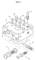
- the housing 20 of the hydraulic unit is provided with bores 21 a, 21 b, 21 c, 21 d, 22a, 22b, 22c, and 22d, in which the valves 12a, 12b, 12c, 12d, 13a, 13b, 13c, and 13d are fitted, respectively, bores 23a, 23b, 24a, and 24b, in which the low-pressure and high-pressure accumulators 14a, 14b, 17a, and 17b are fitted, respectively, bores 25a, 25b, and 26, in which the hydraulic pumps 15a and 15b, and the driving motor 16 that drives the hydraulic pumps 15a and 15b are fitted, respectively, and bores 27a, 27b, 28a, 28b, 28c, and 28d, in which a plurality of connection pipes are fitted, respectively, as is shown in FIG. 3.
- a plurality of flow channels 29 connected between the components mounted to the housing 20 and the connection pipes. In this way, the hydraulic unit as is shown in FIG. 1 is accomplished.
- the housing 20 of the hydraulic unit according to the present invention is manufactured through injection molding of a resin material. Consequently, the housing 20 is easily manufactured.
- a mold 30 for manufacturing the housing 20 according to a first preferred embodiment of the present invention is shown in FIGS. 4 to 8.
- the mold 30 comprises: a lower mold 33 mounted in a stationary frame 31 for defining a housing forming space; an upper mold 34 mounted in a movable frame 32 disposed on the stationary frame 31; a plurality of cores 41, 42, 44, 45, and 46 movable into the housing forming space for forming a plurality of bores in the housing 20; and a removing unit 60 that removes a molded product from the mold after the forming of the housing 20 is completed.
- the lower mold 33 is fixedly attached to the center of the upper part of the stationary frame 31.
- the lower mold 33 is provided at the inner part thereof with a housing forming space, the upper part of which is open. Consequently, the lower part and side parts of the housing are formed in the housing forming space defined in the lower mold 33.
- the lower mold 33 comprises: a side forming member 33a having open upper and lower ends and a square forming space defined therein such that the side parts of the housing 20 can be formed in the side forming member 33a; and a lower forming member 33b attached to the lower end of the side forming member 33a for closing the lower end of the side forming member 33a.
- the upper mold 34 is attached to the lower surface of the movable frame 32, which moves a predetermined distance upward or downward to open or close the upper part of the housing forming space.
- the cores which are used to form the plurality of bores, include a plurality of lower cores 41 attached to the lower forming member 33b of the lower mold 33, an upper core 42 attached to the upper mold 34, a plurality of side cores 44, 45, and 46 disposed such that the side cores 44, 45, and 46 move into and out of the housing forming space through the side forming member 33a of the lower mold 33 in four directions, and flow channel forming cores 41 a and 46a formed at the lower cores 41 and the side cores 44, 45, and 46.
- the lower cores 41 are used to form the bores 21a, 21 b, 21c, 21d, 22a, 22b, 22c, and 22d, which are disposed in the housing 20 such that the plurality of valves 12a, 12b, 12c, 12d, 13a, 13b, 13c, and 13d are inserted in the bores 21 a, 21b, 21 c, 21 d, 22a, 22b, 22c, and 22d.
- the lower cores 41 are attached to the lower forming member 33b such that the lower cores 41 are protruded into the housing forming space from the upper surface of the lower forming member 33b.
- the upper core 42 is used to form the bore 26, which is disposed in the housing 20 such that the driving motor 16 of the hydraulic unit is inserted in the bore 26.
- the upper core 42 is attached to the upper mold 34 such that the upper core 42 is protruded into the housing forming space from the lower surface of the upper mold 34.
- the upper core 42 is provided at the center thereof with an injection channel 43, which is formed through the upper core 42 in the longitudinal direction thereof for allowing molten resin to be injected into the housing forming space therethrough while the upper mold 34 and the lower mold 33 are assembled.
- the plurality of side cores 44, 45, and 46 include the cores 44 used to form the bores 25a and 25b, in which the hydraulic pumps 15a and 15b are inserted, respectively, the cores 45 used to form the bores 23a, 23b, 24a, and 24b, in which the accumulators 14a, 14b, 17a, and 17b are inserted, respectively, and the cores 46 used to form the bores 27a, 27b, 28a, 28b, 28c, and 28d, in which the plurality of connection pipes are inserted.
- the side cores 44, 45, and 46 are disposed such that the side cores 44, 45, and 46 move into and out of the housing forming space through the side forming member 33a of the lower mold 33 and the stationary frame 31.
- the side cores 44, 45, and 46 are connected, at the outside of the stationary frame 31, to hydraulic cylinder-type driving units 50, by which the side cores 44, 45, and 46 are moved inward and outward, respectively.
- the hydraulic cylinder-type driving units 50 are operated, the side cores 44, 45, and 46 are moved inward and outward. In this way, the side cores are moved into or out of the housing forming space.
- the flow channel forming cores 41a and 46a used to form the flow channels in the housing 20 include the cores 41 a vertically extending a predetermined length from the upper ends of the lower cores 41, respectively, and the cores 46a horizontally extending a predetermined length from the ends of the side cores 46, respectively.
- the cores 41 a are formed in the shape of a pin.
- the cores 46a are formed in the shape of a pin.
- the cores 46a extending from the side cores 46 penetrate the lower cores 41 through through-holes 41 b formed at the lower cores 41, as is shown in FIG. 8.
- the flow channels are formed in the housing 20 by means of the flow channel forming cores 41 a and 46a when the mold is assembled.
- the flow channel forming cores 46a extending from the side cores 46 penetrate the lower cores 41. Consequently, the bores formed by means of the lower cores 41 and the bores formed by means of the side cores 46 are connected to each other by means of the flow channels formed by means of the flow channel forming cores 46a.
- the flow channel forming cores 41 a are provided at the lower cores 41, and the flow channel forming cores 46a are provided at the side cores 46 in order to form the flow channels together with the plurality of bores in the course of forming the housing.
- the housing 20 may be formed without using the flow channel forming cores 41 a and 46a, and then the flow channels may be formed in the housing 20 through a cutting process.
- the removing unit comprises: a removing plate 61 disposed below the stationary frame 31 such that the removing plate 61 can be vertically moved a predetermined distance; and a plurality of removing pins 62 fixed to the removing plate 61 such that the removing pins 62 are vertically moved through the lower parts of the lower mold 33 and the stationary frame 31, and thus the removing pins 62 are moved into and out of the housing forming space.
- the removing plate 61 is moved upward, the removing pins 62 are also moved upward through the housing forming space, whereby the molded product is removed from the mold.
- the housing forming space is provided in the mold, as is shown in FIG. 4.
- the plurality of side cores 44, 45, and 46 are moved into the housing forming space of the mold 30 to form the plurality of bores in the housing 20.
- the flow channel forming cores 46a provided at the side cores 46 penetrate the lower cores 41.
- Molten resin is injected into the housing forming space of the mold 30 through the injection channel 43 provided at the upper core 42 of the upper mold 34.
- the resin injected in the housing forming space is solidified to manufacture the housing 20.
- the manufactured housing 20 is removed from the mold 30 as follows. As is shown in FIG. 6, the plurality of side cores 44, 45, and 46 are separated from the housing forming space of the mold 30 so that the housing 20 can be moved upward from the housing forming space of the mold 30. At this time, the flow channel forming cores 46a are also separated from the housing forming space of the mold 30. Subsequently, the upper mold 34 is moved upward such that the upper mold 34 is separated from the lower mold 33, as is shown in FIG. 7. Finally, the removing pins 62 are moved upward by means of the removing plate 61 of the removing unit 60 as the removing plate 61 is moved upward. Consequently, the removing pins 62 are moved into the house forming space of the mold 30, and thus the housing 20 is moved upward by means of the removing pins 62. In this way, the housing 20 is removed from the mold 30.
- FIGS. 9 and 10 show a mold for manufacturing the housing 20 according to a second preferred embodiment of the present invention.
- This embodiment is different from the previously described first embodiment of the present invention in that the side cores 46 used to form the connection pipe insertion bores are rotary cores having thread parts 46 provided at their ends, respectively.
- the cores 46 are rotated by means of motors 46d provided at the hydraulic cylinder-type driving units 50. Consequently, corresponding thread parts are formed at the inner surfaces of the bores by means of the thread parts 46c provided at the ends of the cores 46.
- the cores 46 are easily separated from the molded product as the cores 46 are rotated, in the directions where the cores 46 are separated from the molded product, by means of the motors 46d.
- some of the side cores, i.e., the side cores 46 used to form the connection pipe insertion bores are modified such that the side cores 46 are rotated, although not only the other side cores but also the upper and lower cores may also be modified such that the cores are rotated.
- the present invention provides a mold for manufacturing a housing of a hydraulic unit of an anti-lock brake system for vehicles that allows manufacturing a housing having a complicated structure through injection molding. Consequently, the present invention has the effect that the housing is easily manufactured with increased productivity as compared with the conventional method of manufacturing the housing through an aluminum cutting process. In addition, the manufacturing costs of the housing are reduced.
- flow channels are formed in the housing together with a plurality of bores in the course of forming the housing. Consequently, the housing manufacturing process is simplified.
- thread parts are formed at the inner surfaces of the bores by means of rotary cores having corresponding thread parts in the course of forming the housing. Consequently, the housing manufacturing process is simplified.
Landscapes
- Engineering & Computer Science (AREA)
- Mechanical Engineering (AREA)
- Physics & Mathematics (AREA)
- Manufacturing & Machinery (AREA)
- Electromagnetism (AREA)
- Fluid Mechanics (AREA)
- Transportation (AREA)
- Moulds For Moulding Plastics Or The Like (AREA)
- Injection Moulding Of Plastics Or The Like (AREA)
- Braking Arrangements (AREA)
- Regulating Braking Force (AREA)
Abstract
Description
Claims (12)
- A mold for manufacturing a housing of a hydraulic unit of an anti-lock brake system, the housing having a plurality of bores formed therein such that components, such as a plurality of valves, accumulators, hydraulic pumps, and a driving motor, and a plurality of connection pipes are mounted to the housing through the bores, wherein the mold comprises:a lower mold mounted in a stationary frame for defining a housing forming space where the lower part and side parts of the housing are formed;an upper mold mounted in a movable frame disposed on the stationary frame such that the movable frame is vertically moved a predetermined distance, the upper mold covering the upper part of the housing forming space of the lower mold to form the upper part of the housing;lower cores attached to the lower mold such that the lower cores are protruded from the inner lower surface of the lower mold to form the lower-side bores of the housing;an upper core attached to the upper mold for forming the upper-side bores of the housing; anda plurality of side cores disposed at the lower mold such that the side cores move into and out of the housing forming space defined in the lower mold through the lower mold in four directions to form the bores provided at the four sides of the housing.
- The mold according to claim 1, wherein the lower mold comprises:a side forming member provided to form the side parts of the housing; anda lower forming member attached to the lower end of the side forming member for forming the lower part of the housing.
- The mold according to claim 1, wherein the lower cores include a plurality of cores used to form bores disposed in the housing such that the plurality of valves are inserted in the bores.
- The mold according to claim 1, wherein the side cores include cores used to form bores disposed in the housing such that the hydraulic pumps, the accumulators, and the plurality of connection pipes are inserted in the bores.
- The mold according to claim 1, wherein the upper core includes a core used to form a bore disposed in the housing such that the driving motor is inserted in the bore.
- The mold according to claim 5, wherein the upper core is provided with an injection channel for allowing molten resin to be injected into the housing forming space.
- The mold according to claim 1, further comprising:a plurality of hydraulic cylinder-type driving units that move the side cores into and out of the lower mold through the sides of the lower mold.
- The mold according to claim 1, further comprising:removing pins disposed at the lower mold such that such that the removing pins are moved upward into the housing forming space from the lower part of the lower mold to remove the housing from the housing forming space.
- The mold according to claim 1, further comprising:at least one flow channel forming core provided at the lower cores and the side cores for forming a flow channel in the housing.
- The mold according to claim 9, wherein the side cores include cores used to form bores disposed in the housing such that the hydraulic pumps, the accumulators, and the plurality of connection pipes are inserted in the bores, and wherein one of the cores used to form bores disposed in the housing such that the connection pipes are inserted in the bores is provided with the flow channel forming core, the flow channel forming core penetrating one of the lower cores.
- The mold according to claim 9, wherein the flow channel forming core is connected to at least one of the side cores such that the flow channel forming core is moved inward and outward along with the corresponding side core, and the flow channel forming core penetrates another core when the mold is assembled.
- The mold according to claim 1, wherein at least one of the cores is a rotary core having a thread part formed such that a corresponding thread part is formed at the inner surface of one of the bores by means of the thread part of the rotary core, the rotary core being rotated by means of a motor.
Applications Claiming Priority (6)
| Application Number | Priority Date | Filing Date | Title |
|---|---|---|---|
| KR10-2003-0080674A KR100506012B1 (en) | 2003-11-14 | 2003-11-14 | Mold for molding housing of hydraulic unit for anti-lock brake system |
| KR10-2003-0080671A KR100506013B1 (en) | 2003-11-14 | 2003-11-14 | Mold for molding housing of hydraulic unit for anti-lock brake system |
| KR10-2003-0080670A KR100515990B1 (en) | 2003-11-14 | 2003-11-14 | Mold for molding housing of hydraulic unit for anti-lock brake system |
| KR2003080674 | 2003-11-14 | ||
| KR2003080670 | 2003-11-14 | ||
| KR2003080671 | 2003-11-14 |
Publications (3)
| Publication Number | Publication Date |
|---|---|
| EP1531033A2 true EP1531033A2 (en) | 2005-05-18 |
| EP1531033A3 EP1531033A3 (en) | 2005-05-25 |
| EP1531033B1 EP1531033B1 (en) | 2009-09-09 |
Family
ID=34437618
Family Applications (1)
| Application Number | Title | Priority Date | Filing Date |
|---|---|---|---|
| EP04256600A Expired - Lifetime EP1531033B1 (en) | 2003-11-14 | 2004-10-26 | Mold for manufacturing housing of hydraulic unit of anti-lock brake system |
Country Status (4)
| Country | Link |
|---|---|
| US (1) | US7291005B2 (en) |
| EP (1) | EP1531033B1 (en) |
| CN (1) | CN100421904C (en) |
| DE (1) | DE602004023045D1 (en) |
Cited By (4)
| Publication number | Priority date | Publication date | Assignee | Title |
|---|---|---|---|---|
| EP1724089A1 (en) * | 2005-05-19 | 2006-11-22 | ElringKlinger AG | Process of manufacturing a plastic part, mould and plastic part obtainable from that process |
| WO2009065558A1 (en) * | 2007-11-23 | 2009-05-28 | Knorr-Bremse Systeme für Nutzfahrzeuge GmbH | Method for producing a pneumatic device of a vehicle comprising plastic parts |
| EP2216158A1 (en) * | 2009-02-05 | 2010-08-11 | Etervind AB | Core assembly for an injection moulding-machine |
| CN102785354A (en) * | 2012-08-23 | 2012-11-21 | 上海隆利安包装材料有限公司 | Efficient moving mold |
Families Citing this family (4)
| Publication number | Priority date | Publication date | Assignee | Title |
|---|---|---|---|---|
| CN102230991B (en) * | 2009-10-23 | 2013-01-09 | 鸿富锦精密工业(深圳)有限公司 | Optical fiber coupling connector |
| CN102950715B (en) * | 2011-08-31 | 2016-01-20 | 苏州莱斯豪精密铸造有限公司 | The injection mold of work feed rolling wheel support |
| CN103057057B (en) * | 2011-10-20 | 2016-01-27 | 汉达精密电子(昆山)有限公司 | Ejection forced-demoulding mechanism |
| CN108790060A (en) * | 2018-04-28 | 2018-11-13 | 芜湖盈奇塑业有限公司 | Die assembly |
Family Cites Families (15)
| Publication number | Priority date | Publication date | Assignee | Title |
|---|---|---|---|---|
| US2003232A (en) * | 1933-05-15 | 1935-05-28 | Continental Diamond Fibre Co | Hollow articles, such as pipe fittings and the like, and method of making the same |
| DE4020448C2 (en) * | 1990-06-27 | 1998-10-29 | Teves Gmbh Alfred | Brake pressure transmitter, especially for slip-controlled brake systems |
| ES2075189T3 (en) * | 1990-10-24 | 1995-10-01 | Volvo Ab | CHECK VALVE. |
| US5226450A (en) * | 1992-05-14 | 1993-07-13 | Taylor Hpl Pty Ltd. | Fluid mixing and flow control apparatus |
| DE4306222A1 (en) | 1992-10-09 | 1994-09-01 | Teves Gmbh Alfred | Hydraulic unit for slip-controlled brake systems |
| DE4325410A1 (en) | 1993-07-29 | 1995-02-02 | Teves Gmbh Alfred | Electro-hydraulic pressure control device |
| US5403179A (en) * | 1993-10-29 | 1995-04-04 | Ramsey; William C. | Collapsible mold core assembly |
| DE19709744A1 (en) * | 1997-03-10 | 1998-09-17 | Itt Mfg Enterprises Inc | Pressure controller especially for vehicle brakes |
| EP0932761B1 (en) | 1997-07-30 | 2004-10-06 | Robert Bosch Gmbh | Piston pump |
| KR100328227B1 (en) * | 1997-12-30 | 2002-04-17 | 밍 루 | Anti-lock brake system |
| DE19837207A1 (en) * | 1998-03-03 | 1999-09-09 | Itt Mfg Enterprises Inc | Solenoid valve |
| JP4032523B2 (en) * | 1998-09-08 | 2008-01-16 | アイシン精機株式会社 | Manufacturing method of fuel distribution pipe |
| CN2368761Y (en) * | 1999-03-30 | 2000-03-15 | 李松灵 | Antilocking device for vehicle |
| US6355201B1 (en) * | 2000-09-07 | 2002-03-12 | Captive Plastics, Inc. | Tamper-indicating closure with resilient locking projections |
| US7128547B2 (en) * | 2004-01-13 | 2006-10-31 | Chien-Min Sung | High pressure split die and associated methods |
-
2004
- 2004-10-26 DE DE602004023045T patent/DE602004023045D1/en not_active Expired - Lifetime
- 2004-10-26 EP EP04256600A patent/EP1531033B1/en not_active Expired - Lifetime
- 2004-10-29 CN CNB2004100942019A patent/CN100421904C/en not_active Expired - Fee Related
- 2004-10-29 US US10/977,730 patent/US7291005B2/en not_active Expired - Fee Related
Cited By (6)
| Publication number | Priority date | Publication date | Assignee | Title |
|---|---|---|---|---|
| EP1724089A1 (en) * | 2005-05-19 | 2006-11-22 | ElringKlinger AG | Process of manufacturing a plastic part, mould and plastic part obtainable from that process |
| WO2009065558A1 (en) * | 2007-11-23 | 2009-05-28 | Knorr-Bremse Systeme für Nutzfahrzeuge GmbH | Method for producing a pneumatic device of a vehicle comprising plastic parts |
| EP2216158A1 (en) * | 2009-02-05 | 2010-08-11 | Etervind AB | Core assembly for an injection moulding-machine |
| WO2010089362A1 (en) * | 2009-02-05 | 2010-08-12 | Etervind Ab | Core assembly for an injection moulding-machine |
| US8585955B2 (en) | 2009-02-05 | 2013-11-19 | Etervind Ab | Core assembly for an injection moulding-machine |
| CN102785354A (en) * | 2012-08-23 | 2012-11-21 | 上海隆利安包装材料有限公司 | Efficient moving mold |
Also Published As
| Publication number | Publication date |
|---|---|
| EP1531033A3 (en) | 2005-05-25 |
| US20050106284A1 (en) | 2005-05-19 |
| DE602004023045D1 (en) | 2009-10-22 |
| CN100421904C (en) | 2008-10-01 |
| US7291005B2 (en) | 2007-11-06 |
| EP1531033B1 (en) | 2009-09-09 |
| CN1660557A (en) | 2005-08-31 |
Similar Documents
| Publication | Publication Date | Title |
|---|---|---|
| US10184468B2 (en) | Pump housing of a motor vehicle hydraulic unit with at least one main cylinder connection opening | |
| US7967394B2 (en) | Hydraulic unit of electronic control brake system | |
| US7291005B2 (en) | Mold for manufacturing housing of hydraulic unit of anti-lock brake system | |
| CN105109473A (en) | Hydraulic brake system | |
| CN103958095A (en) | Three-plate die casting tool having a gating system, and gating system | |
| EP1531107B1 (en) | Hydraulic unit for an anti-lock brake system and method of manufacturing the same | |
| EP1531106B1 (en) | Hydraulic unit of anti-lock brake system and method of manufacturing the same | |
| CN102785655B (en) | Check valve of hydraulic brake system | |
| EP1531105B1 (en) | Hydraulic unit for an anti-lock brake system and method of manufacturing the same | |
| KR100515990B1 (en) | Mold for molding housing of hydraulic unit for anti-lock brake system | |
| KR100506013B1 (en) | Mold for molding housing of hydraulic unit for anti-lock brake system | |
| KR100506012B1 (en) | Mold for molding housing of hydraulic unit for anti-lock brake system | |
| KR100536287B1 (en) | Hydraulic unit for anti-lock brake system and manufacturing method thereof | |
| KR100536283B1 (en) | Hydraulic unit for anti-lock brake system and manufacturing method thereof | |
| KR100536280B1 (en) | Hydraulic unit for anti-lock brake system and manufacturing method thereof | |
| KR100536291B1 (en) | Hydraulic unit for anti-lock brake system and manufacturing method thereof | |
| KR20050046408A (en) | Hydraulic unit for anti-lock brake system and manufacturing method thereof | |
| KR20050046416A (en) | Hydraulic unit for anti-lock brake system and manufacturing method thereof | |
| KR20090077211A (en) | Master cylinder for brake system | |
| KR20120103863A (en) | Check valve of hydraulic break system |
Legal Events
| Date | Code | Title | Description |
|---|---|---|---|
| PUAI | Public reference made under article 153(3) epc to a published international application that has entered the european phase |
Free format text: ORIGINAL CODE: 0009012 |
|
| PUAL | Search report despatched |
Free format text: ORIGINAL CODE: 0009013 |
|
| 17P | Request for examination filed |
Effective date: 20041112 |
|
| AK | Designated contracting states |
Kind code of ref document: A2 Designated state(s): AT BE BG CH CY CZ DE DK EE ES FI FR GB GR HU IE IT LI LU MC NL PL PT RO SE SI SK TR |
|
| AX | Request for extension of the european patent |
Extension state: AL HR LT LV MK |
|
| AK | Designated contracting states |
Kind code of ref document: A3 Designated state(s): AT BE BG CH CY CZ DE DK EE ES FI FR GB GR HU IE IT LI LU MC NL PL PT RO SE SI SK TR |
|
| AX | Request for extension of the european patent |
Extension state: AL HR LT LV MK |
|
| RIC1 | Information provided on ipc code assigned before grant |
Ipc: 7B 29C 45/33 A Ipc: 7B 29C 45/26 B Ipc: 7B 60T 8/36 B |
|
| AKX | Designation fees paid |
Designated state(s): DE FR GB IT |
|
| 17Q | First examination report despatched |
Effective date: 20051220 |
|
| GRAP | Despatch of communication of intention to grant a patent |
Free format text: ORIGINAL CODE: EPIDOSNIGR1 |
|
| GRAS | Grant fee paid |
Free format text: ORIGINAL CODE: EPIDOSNIGR3 |
|
| GRAA | (expected) grant |
Free format text: ORIGINAL CODE: 0009210 |
|
| AK | Designated contracting states |
Kind code of ref document: B1 Designated state(s): DE FR GB IT |
|
| REG | Reference to a national code |
Ref country code: GB Ref legal event code: FG4D |
|
| REF | Corresponds to: |
Ref document number: 602004023045 Country of ref document: DE Date of ref document: 20091022 Kind code of ref document: P |
|
| PLBE | No opposition filed within time limit |
Free format text: ORIGINAL CODE: 0009261 |
|
| STAA | Information on the status of an ep patent application or granted ep patent |
Free format text: STATUS: NO OPPOSITION FILED WITHIN TIME LIMIT |
|
| REG | Reference to a national code |
Ref country code: FR Ref legal event code: ST Effective date: 20100630 |
|
| PG25 | Lapsed in a contracting state [announced via postgrant information from national office to epo] |
Ref country code: FR Free format text: LAPSE BECAUSE OF NON-PAYMENT OF DUE FEES Effective date: 20091109 |
|
| 26N | No opposition filed |
Effective date: 20100610 |
|
| GBPC | Gb: european patent ceased through non-payment of renewal fee |
Effective date: 20091209 |
|
| PG25 | Lapsed in a contracting state [announced via postgrant information from national office to epo] |
Ref country code: GB Free format text: LAPSE BECAUSE OF NON-PAYMENT OF DUE FEES Effective date: 20091209 |
|
| PG25 | Lapsed in a contracting state [announced via postgrant information from national office to epo] |
Ref country code: IT Free format text: LAPSE BECAUSE OF FAILURE TO SUBMIT A TRANSLATION OF THE DESCRIPTION OR TO PAY THE FEE WITHIN THE PRESCRIBED TIME-LIMIT Effective date: 20090909 |
|
| PGFP | Annual fee paid to national office [announced via postgrant information from national office to epo] |
Ref country code: DE Payment date: 20121024 Year of fee payment: 9 |
|
| REG | Reference to a national code |
Ref country code: DE Ref legal event code: R119 Ref document number: 602004023045 Country of ref document: DE Effective date: 20140501 |
|
| PG25 | Lapsed in a contracting state [announced via postgrant information from national office to epo] |
Ref country code: DE Free format text: LAPSE BECAUSE OF NON-PAYMENT OF DUE FEES Effective date: 20140501 |