EP1530375A2 - Lens correction using processed yuv data - Google Patents
Lens correction using processed yuv data Download PDFInfo
- Publication number
- EP1530375A2 EP1530375A2 EP04256059A EP04256059A EP1530375A2 EP 1530375 A2 EP1530375 A2 EP 1530375A2 EP 04256059 A EP04256059 A EP 04256059A EP 04256059 A EP04256059 A EP 04256059A EP 1530375 A2 EP1530375 A2 EP 1530375A2
- Authority
- EP
- European Patent Office
- Prior art keywords
- reference image
- abs
- distance value
- value
- distance
- Prior art date
- Legal status (The legal status is an assumption and is not a legal conclusion. Google has not performed a legal analysis and makes no representation as to the accuracy of the status listed.)
- Granted
Links
Images


Classifications
-
- H—ELECTRICITY
- H04—ELECTRIC COMMUNICATION TECHNIQUE
- H04N—PICTORIAL COMMUNICATION, e.g. TELEVISION
- H04N25/00—Circuitry of solid-state image sensors [SSIS]; Control thereof
- H04N25/60—Noise processing, e.g. detecting, correcting, reducing or removing noise
- H04N25/61—Noise processing, e.g. detecting, correcting, reducing or removing noise the noise originating only from the lens unit, e.g. flare, shading, vignetting or "cos4"
-
- H—ELECTRICITY
- H04—ELECTRIC COMMUNICATION TECHNIQUE
- H04N—PICTORIAL COMMUNICATION, e.g. TELEVISION
- H04N25/00—Circuitry of solid-state image sensors [SSIS]; Control thereof
- H04N25/60—Noise processing, e.g. detecting, correcting, reducing or removing noise
- H04N25/61—Noise processing, e.g. detecting, correcting, reducing or removing noise the noise originating only from the lens unit, e.g. flare, shading, vignetting or "cos4"
- H04N25/611—Correction of chromatic aberration
Definitions
- the present invention relates to image sensors, and more particularly, to a lens correction method for use on the processed output of an image sensor.
- CMOS complementary metal-oxide-semiconductor
- CCD charge coupled device
- MOS metal-oxide-semiconductor
- a CCD imaging device includes at least two integrated circuits: one for the CCD sensor and one for the signal processing logic.
- CMOS active pixel sensor Another class of image sensors is the CMOS active pixel sensor.
- an active pixel sensor refers to an electronic image sensor with active devices, such as transistors, that are associated with each pixel.
- the active pixel sensor has the advantage of being able to incorporate both signal processing and sensing circuitry within the same integrated circuit because of the CMOS manufacturing techniques.
- image sensors are now commonplace and are used in small form factor applications, such as personal digital assistants (PDAs) and cell phones.
- PDAs personal digital assistants
- vignetting undesirable effects, such as shading, "dark corners", color differences, “reddishness”, and vignetting.
- FIG. 1 shows one approach for attempting to correct some of the problems mentioned above.
- FIG. 1 shows lens 102, a sensor array 104 associated with an image sensor module (not shown), Bayer RGB data 106, a lens correction process 108, an RGB data output 110, image processing 112, and image processed YUV/RGB data 114.
- the lens correction processing is performed on the raw RBG data output 110.
- AVB automatic white balance 112a
- color matrix 112b color gain/hue 112c
- color gamma correction 112d color gamma correction 112d
- YUV conversion 112e YUV conversion 112e
- the present invention provides a method for applying a lens correction according to Claim 1
- the present invention is a lens correction method and apparatus which can improve, enhance, or solve the shading effects of an image produced by a given lens, dark corner effects on the image, color differences between the center and corners of the image, and vignetting problems in various types of image sensors.
- FIG. 2 is a schematic diagram that illustrates a process for lens correction in accordance with certain embodiments of the invention.
- a lens 202 shows a lens 202, a sensor array 204 associated with an image sensor module (not shown), Bayer RGB data 206, a lens correction process 208, image processing 212, and image processed YUV/RGB data 214.
- Image processing 212 comprises controls associated with automatic white balance 112a (AWB), color matrix 112b, color gain/hue 112c, color gamma correction 112d, YUV conversion 112e, and other image processing 112f.
- AVB automatic white balance 112a
- color matrix 112b comprises controls associated with automatic white balance 112a (AWB), color matrix 112b, color gain/hue 112c, color gamma correction 112d, YUV conversion 112e, and other image processing 112f.
- lens correction process 208 is applied to the image processed YUV data 214. As seen in FIG.
- the lens correction method may be implemented on a digital signal processor (DSP), a backend processor, or an image processor.
- DSP digital signal processor
- the lens correction method can be implemented by software on a general purpose central processing unit (CPU) or microprocessor or by a combination of software and hardware.
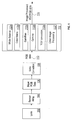
- FIG. 3 is a schematic diagram illustrating that the lens correction is performed on the YUV data in accordance with certain embodiments of the invention.
- FIG. 3 shows that a Y correction value 204a is applied to the Y data 202a to result in a corrected Y data 206a.
- a U correction value 204b is applied to the U data 202b to result in a corrected U data 206b.
- a V correction value 204c is applied to the V data 202c to result in a corrected V data 206c.
- any pixel to which a correction value (either Y, U or V correction value) is to be applied is referred to herein as the target pixel.
- the Y, U and V correction values are based on the distance of the target pixel relative to the center of the reference image.
- the U correction value is based on a first distance value.
- a U correction value is bounded by a minimum and a maximum U correction limit, which are constants.
- the minimum and maximum U correction limits may be user-selected based on properties of the lens. The user may select such minimum and maximum U correction limits so that the resulting U correction value is neither insufficient nor excessive when applied to a given target pixel.
- the distance value may be determined by a function defined by Equation 10 below, as an example.
- the first distance value may be defined by assuming that the pixels in the reference image trace a set of imaginary concentric rhombuses (diamond shape) emanating from the center of the reference image. The same U correction value is applied to each pixel (target pixel) on a given rhombus.
- the distance value may be determined by a function defined by Equation 11 below, as an example.
- the first distance value may be defined by assuming that the pixels in the reference image trace a set of imaginary concentric rectangles emanating from the center of the reference image. The same U correction value is applied to each pixel (target pixel) on a given rectangle.
- the distance value may be determined by a function defined by Equation 12 below, as an example.
- the first distance value may be defined by assuming that the pixels in the reference image trace a set of imaginary concentric polygons that are approximately ring-shaped and emanating from the center of the reference image. The same U correction value is applied to each pixel (target pixel) on a given polygon.
- the distance value may be determined by a function defined by Equations 13a, 13b, 13c and 13d below, for example.
- Such polygons are intended to be approximations of the concentric rings of Equation 10.
- the polygons of Equations 13a, 13b, 13c and 13d are twelve-sided. However, the embodiments are not restricted to twelve-sided polygons. The greater the number of sides to a given polygon, the closer the approximation to a ring. Thus, the level of approximation to a ring can be user-selected.
- the U correction value may either be increased in decreased by a luminance parameter that is related to the Y value of the target pixel.
- a luminance parameter is user-selected based on whether the Y value of the target pixel satisfies certain luminance-related conditions.
- the luminance-related conditions associated with the U correction value may be defined by Equations 8a, 8b, and 8c below, for example.
- the U correction value namely, DeltaU
- Equation 5 the U correction value
- the V correction value is based on a first distance value.
- a V correction value is bounded by a minimum and a maximum V correction limit, which are constants.
- the minimum and maximum V correction limits may be user-selected based on properties of the lens. The user may select such minimum and maximum V correction limits so that the resulting V correction value is neither insufficient nor excessive when applied to a given target pixel.
- the distance value may be determined by a function defined by Equation 10 below, as an example.
- the first distance value may be defined by assuming that the pixels in the reference image trace a set of imaginary concentric rhombuses (diamond shape) emanating from the center of the reference image. The same V correction value is applied to each pixel (target pixel) on a given rhombus.
- the distance value may be determined by a function defined by Equation 11 below, as an example.
- the first distance value may be defined by assuming that the pixels in the reference image trace a set of imaginary concentric rectangles emanating from the center of the reference image. The same V correction value is applied to each pixel (target pixel) on a given rectangle.
- the distance value may be determined by a function defined by Equation 12 below, as an example.
- the first distance value may be defined by assuming that the pixels in the reference image trace a set of imaginary concentric polygons that are approximately ring-shaped and emanating from the center of the reference image. The same V correction value is applied to each pixel (target pixel) on a given polygon.
- the distance value may be determined by a function defined by Equations 13a, 13b, 13c and 13d below, for example.
- Such polygons are intended to be approximations of the concentric rings of Equation 10.
- the polygons of Equations 13a, 13b, 13c and 13d are twelve-sided. However, the embodiments are not restricted to twelve-sided polygons. The greater the number of sides to a given polygon, the closer the approximation to a ring. Thus, the level of approximation to a ring can be user-selected.
- the V correction value may either be increased in decreased by a luminance parameter that is related to the Y value of the target pixel.
- a luminance parameter is user-selected based on whether the Y value of the target pixel satisfies certain luminance-related conditions.
- the luminance-related conditions associated with the V correction value may be defined by Equations 9a, 9b, and 9c below, for example.
- V correction value namely, DeltaV
- Equation 6 the V correction value
- the Y correction value is based on is based on a second distance value.
- a Y correction value is bounded by a minimum and a maximum Y correction limit, which are constants.
- the minimum and maximum Y correction limits may be user-selected based on properties of the lens. The user may select such minimum and maximum Y correction limits so that the resulting Y correction value is neither insufficient nor excessive when applied to a given target pixel.
- the second distance value is based on the first distance value (as previously described above), which in turn is augmented by user-selected constants. Such user-selected constants are based on the F value of the lens that is being corrected.
- the second distance value may be defined by Equation 14 below, as an example, according to certain embodiments.
- the Y correction value is based on a smoothing parameter, referred to herein as an alpha function.
- a smoothing parameter referred to herein as an alpha function.
- the alpha function is such that it has the effect of smoothing out the discontinuous point at the lower limit of the Y correction curve.
- the smoothing parameter may be defined by Equation 7 below, as an example, according to certain embodiments.
- C1 is the location associated with the discontinuous point at the lower limit of the Y correction curve.
- C3, C4 and C5 are selected by the user and depend upon the degree of smoothing that is desired.
- the Y correction value namely, YGain
- Equation 4 Equation 4 below, as an example, according to certain embodiments.
- constants and coefficients above depend upon the specific lens/image sensor combination.
- these constants and coefficients are obtained through experimental observations of a reference image obtained from the lens/image sensor combination and can be selected by the user based on such observations.
- FIG. 4 is a diagram illustrating a set of coordinates used in the correction method according to certain embodiments of the invention.
- FIG. 4 shows a reference image 402 with length 404 (XSIZE) in the X direction, height 406 (YSIZE) in the Y direction.
- Reference image 402 is associated with a coordinate system having an origin [0,0] at location 410.
- the center of reference image 402 is at location 412 with coordinates [XSIZE/2, YSIZE/2].
- the location of pixel 408 may be described with reference to location 412.
- the location of pixel 408 may also be described with reference to an arbitrary location such as location 418 with coordinates [XSIZE/2 + XSHIFT, YSIZE/2 + YSHIFT].
- XSHIFT and YSHIFT represent the distances from location 412 in the X and Y direction, respectively.
- NormalizeValue is a value that depends on whether the implementation is an 8 bit or 16 bit etc., implementation.
- the Function_Distance(x,y) can be one of the following equations or other equivalent Distance function.
- Equation 10 is not as easy to implement in hardware (cost will be high) and it require more calculation resources in software. However, the resultant image for Equation 10 is relatively good.
- Equation 11 is easy to implement in hardware (cost will be low) and it requires relatively small computational resources in software. However, the resultant image is not as good as that of Equation 10.
- Equation 12 is easy to implement in hardware (cost will be low) and it requires relatively small computational resources in software. However, the resultant image is not as good as that of Equation 10.
- Equations 13a, 13b, 13c, 13d are easy to implement in hardware (cost will be low) and it requires low amounts of computational resources in software. Further, the resultant image is good.
Landscapes
- Engineering & Computer Science (AREA)
- Multimedia (AREA)
- Signal Processing (AREA)
- Image Processing (AREA)
- Color Image Communication Systems (AREA)
- Facsimile Image Signal Circuits (AREA)
- Processing Of Color Television Signals (AREA)
- Studio Devices (AREA)
Abstract
Description
YGain is the Y correction value
DeltaU is the U correction value
DeltaV is the V correction value


- c1, c2, c3, c4, c5, c6, c7, c8, c9, c10, c11, c12, c13, c16, c17 are constants.
- YMINLIMIT : constant value
- YMAXLIMIT : constant value
- UMINLIMIT : constant value
- UMAXLIMIT : constant value
- VMINLIMIT : constant value
- VMAXLIMIT : constant value
- YOFFSET : offset value
- UOFFSET : offset value
- VOFFSET : offset value
- YCOEFF: coefficient value
- UCOEFF: coefficient value
- VCOEFF: coefficient value
Claims (42)
- A method for applying a lens correction to image data that is associated with a lens, the method comprising:converting the image data to a YUV color space to form YUV image data, if the image data is not in the YUV color space;applying image processing procedures to the YUV image data to form image processed YUV data; andapplying the lens correction to the image processed YUV data.
- The method of Claim 1, wherein applying the lens correction further comprises:applying a Y correction value to a Y component of the image processed YUV data;applying a U correction value to a U component of the image processed YUV data; andapplying a V correction value to a V component of the image processed YUV data.
- The method of Claim 1, wherein applying the lens correction further comprises:multiplying a Y component of the image processed YUV data by a Y correction value;adding a U component of the image processed YUV data to a U correction value; andadding a V component of the image processed YUV data to a V correction value.
- The method of Claim 2, wherein the U correction value is based on a first distance value, wherein the first distance value is associated with a location of a target pixel in a reference image from a reference point of the reference image.
- The method of Claim 2, wherein the U correction value is based on a luminance parameter, wherein the luminance parameter is determined based on whether the Y component of the image processed YUV data falls within a pre-selected luminance range..
- The method of Claim 2, wherein the U correction value is based on a maximum correction limit and a minimum correction limit.
- The method of Claim 6, wherein the maximum correction limit and the minimum correction limit are user-selected.
- The method of Claim 6, wherein the maximum correction limit and the minimum correction limit are based on properties of the lens.
- The method of Claim 4, wherein the first distance value is calculated by assuming that target pixels in the reference image lie in a plurality of concentric rings emanating from the reference point of the reference image.
- The method of Claim 4, wherein the first distance value is calculated byDx = abs(HalfX - x + XSHIFT);Dy = abs(HalfY - y + YSHIFT);HalfX is half a length of the reference image in an x direction; andHalfY is half a width of the reference image in a y direction.
- The method of Claim 4, wherein the first distance value is calculated by assuming that target pixels in the reference image lie in a plurality of concentric rectangles emanating from the reference point of the reference image.
- The method of Claim 4, wherein the first distance value is calculated byDx = abs(HalfX - x + XSHIFT);Dy = abs(HalfY - y + YSHIFT);HalfX is half a length of the reference image in an x direction; andHalfY is half a width of the reference image in a y direction.
- The method of Claim 4, wherein the first distance value is calculated by assuming that target pixels in the reference image lie in a plurality of concentric rhombuses emanating from the reference point of the reference image.
- The method of Claim 4, wherein the first distance value is calculated byDx = abs(HalfX - x + XSHIFT);Dy = abs(HalfY - y + YSHIFT);HalfX is half a length of the reference image in an x direction; andHaIfY is half a width of the reference image in a y direction.
- The method of Claim 4, wherein the first distance value is calculated by assuming that target pixels in the reference image lie in a plurality of concentric polygons emanating from the reference point of the reference image, wherein the plurality of concentric polygons are substantially ring-shaped.
- The method of Claim 4, wherein the first distance value is calculated by
If (Dx > (Dy<<2))
then,
then,
then,Dx = abs(HalfX - x + XSHIFT);Dy = abs(HalfY - y + YSHIFT);HalfX is half a length of the reference image in an x direction; andHalfY is half a width of the reference image in a y direction. - The method of Claim 2, wherein the V correction value is based on a first distance value, wherein the first distance value is associated with a location of a target pixel in a reference image from a reference point of the reference image.
- The method of Claim 2, wherein the V correction value is based on a luminance parameter, wherein the luminance parameter is determined based on whether the Y component of the image processed YUV data falls within a pre-selected luminance range.
- The method of Claim 2, wherein the V correction value is based on a maximum correction limit and a minimum correction limit.
- The method of Claim 19, wherein the maximum correction limit and the minimum correction limit are user-selected.
- The method of Claim 19, wherein the maximum correction limit and the minimum correction limit are based on properties of the lens.
- The method of Claim 17, wherein the first distance value is calculated by assuming that target pixels in the reference image lie in a plurality of concentric rings emanating from the reference point of the reference image.
- The method of Claim 17, wherein the first distance value is calculated byDx = abs(HalfX - x + XSHIFT);Dy = abs(HalfY - y + YSHIFT);HalfX is half a length of the reference image in an x direction; andHalfY is half a width of the reference image in a y direction.
- The method of Claim 17, wherein the first distance value is calculated by assuming that target pixels in the reference image lie in a plurality of concentric rectangles emanating from the reference point of the reference image.
- The method of Claim 17, wherein the first distance value is calculated byDx = abs(HalfX - x + XSHIFT);Dy = abs(HalfY - y + YSHIFT);HalfX is half a length of the reference image in an x direction; andHalfY is half a width of the reference image in a y direction.
- The method of Claim 17, wherein the first distance value is calculated by assuming that target pixels in the reference image lie in a plurality of concentric rhombuses emanating from the reference point of the reference image.
- The method of Claim 17, wherein the first distance value is calculated byDx = abs(HalfX - x + XSHIFT);Dy = abs(HalfY - y + YSHIFT);HalfX is half a length of the reference image in an x direction; andHaIfY is half a width of the reference image in a y direction.
- The method of Claim 17, wherein the first distance value is calculated by assuming that target pixels in the reference image lie in a plurality of concentric polygons emanating from the reference point of the reference image, wherein the plurality of concentric polygons are substantially ring-shaped.
- The method of Claim 17, wherein the first distance value is calculated by
If (Dx > (Dy<<2))
then,
then,
then,Dx = abs(HalfX - x + XSHIFT);Dy = abs(HalfY - y + YSHIFT);HalfX is half a length of the reference image in an x direction; andHalfY is half a width of the reference image in a y direction. - The method of Claim 2, wherein the Y correction value is based on a second distance value, wherein the second distance value is in turn based on a first distance and one or more luminance parameters based on an F value of the lens.
- The method of Claim 2, wherein the Y correction value is based on a smoothing parameter, wherein the smoothing parameter is user-selected based on a desired amount of smoothing.
- The method of Claim 2, wherein the Y correction value is based on a maximum correction limit and a minimum correction limit.
- The method of Claim 32, wherein the maximum correction limit and the minimum correction limit are user-selected.
- The method of Claim 32, wherein the maximum correction limit and the minimum correction limit are based on properties of the lens.
- The method of Claim 30, wherein the first distance value is calculated by assuming that target pixels in the reference image lie in a plurality of concentric rings emanating from the reference point of the reference image.
- The method of Claim 30, wherein the first distance value is calculated byDx = abs(HalfX - x + XSHIFT);Dy = abs(HalfY - y + YSHIFT);HalfX is half a length of the reference image in an x direction; andHalfY is half a width of the reference image in a y direction.
- The method of Claim 30, wherein the first distance value is calculated by assuming that target pixels in the reference image lie in a plurality of concentric rectangles emanating from the reference point of the reference image.
- The method of Claim 30, wherein the first distance value is calculated byDx = abs(HalfX - x + XSHIFT);Dy = abs(HalfY - y + YSHIFT);HalfX is half a length of the reference image in an x direction; andHalfY is half a width of the reference image in a y direction.
- The method of Claim 30, wherein the first distance value is calculated by assuming that target pixels in the reference image lie in a plurality of concentric rhombuses emanating from the reference point of the reference image.
- The method of Claim 30, wherein the first distance value is calculated byDx = abs(HalfX - x + XSHIFT);Dy = abs(HalfY - y + YSHIFT);HalfX is half a length of the reference image in an x direction; andHalfY is half a width of the reference image in a y direction.
- The method of Claim 30, wherein the first distance value is calculated by assuming that target pixels in the reference image lie in a plurality of concentric polygons emanating from the reference point of the reference image, wherein the plurality of concentric polygons are substantially ring-shaped.
- The method of Claim 30, wherein the first distance value is calculated by
If (Dx > (Dy<<2))
then,
then,
then,Dx = abs(HalfX - x + XSHIFT);Dy = abs(HalfY - y + YSHIFT);HalfX is half a length of the reference image in an x direction; andHalfY is half a width of the reference image in a y direction.
Applications Claiming Priority (4)
| Application Number | Priority Date | Filing Date | Title |
|---|---|---|---|
| US51773503P | 2003-11-06 | 2003-11-06 | |
| US517735P | 2003-11-06 | ||
| US758385 | 2004-01-13 | ||
| US10/758,385 US7355639B2 (en) | 2003-11-06 | 2004-01-13 | Lens correction using processed YUV data |
Publications (3)
| Publication Number | Publication Date |
|---|---|
| EP1530375A2 true EP1530375A2 (en) | 2005-05-11 |
| EP1530375A3 EP1530375A3 (en) | 2008-03-26 |
| EP1530375B1 EP1530375B1 (en) | 2018-11-07 |
Family
ID=34437352
Family Applications (1)
| Application Number | Title | Priority Date | Filing Date |
|---|---|---|---|
| EP04256059.9A Expired - Lifetime EP1530375B1 (en) | 2003-11-06 | 2004-09-30 | Lens correction using processed yuv data |
Country Status (4)
| Country | Link |
|---|---|
| US (1) | US7355639B2 (en) |
| EP (1) | EP1530375B1 (en) |
| CN (1) | CN1617597B (en) |
| TW (1) | TWI361904B (en) |
Cited By (1)
| Publication number | Priority date | Publication date | Assignee | Title |
|---|---|---|---|---|
| US8131073B2 (en) | 2008-09-04 | 2012-03-06 | Csr Technology Inc. | Apparatus, method, and manufacture for correcting color shading in CMOS image sensors |
Families Citing this family (6)
| Publication number | Priority date | Publication date | Assignee | Title |
|---|---|---|---|---|
| US7612805B2 (en) | 2006-07-11 | 2009-11-03 | Neal Solomon | Digital imaging system and methods for selective image filtration |
| KR101589310B1 (en) * | 2009-07-08 | 2016-01-28 | 삼성전자주식회사 | LENS SHADING CORRECTION METHOD AND APPARATUS |
| TWI427488B (en) * | 2010-04-23 | 2014-02-21 | Realtek Semiconductor Corp | Distance computing apparatus, lens correcting system and method applying the distance computing apparatus |
| CN104811587A (en) * | 2015-04-21 | 2015-07-29 | 深圳市载德光电技术开发有限公司 | Image brightness chrominance adjustment method, device and system |
| CN111612700B (en) * | 2019-02-26 | 2023-05-26 | 杭州海康威视数字技术股份有限公司 | image enhancement method |
| KR102812092B1 (en) * | 2019-11-25 | 2025-05-23 | 엘지이노텍 주식회사 | Camera module |
Family Cites Families (12)
| Publication number | Priority date | Publication date | Assignee | Title |
|---|---|---|---|---|
| JPH0793563A (en) * | 1993-09-21 | 1995-04-07 | Canon Inc | Image processing device |
| US5819035A (en) * | 1995-10-20 | 1998-10-06 | Matsushita Electric Industrial Co., Ltd. | Post-filter for removing ringing artifacts of DCT coding |
| US6115022A (en) * | 1996-12-10 | 2000-09-05 | Metavision Corporation | Method and apparatus for adjusting multiple projected raster images |
| JPH11250240A (en) * | 1998-02-27 | 1999-09-17 | Kyocera Corp | Digital imaging device that performs distortion correction using YUV data |
| US6603885B1 (en) * | 1998-04-30 | 2003-08-05 | Fuji Photo Film Co., Ltd. | Image processing method and apparatus |
| WO2001001675A2 (en) * | 1999-06-30 | 2001-01-04 | Logitech, Inc. | Video camera with major functions implemented in host software |
| US6791609B2 (en) * | 1999-12-20 | 2004-09-14 | Texas Instruments Incorporated | Digital still camera system and method |
| JP2002237998A (en) * | 2001-02-07 | 2002-08-23 | Sony Corp | Screen correction method and imaging device |
| JP3539394B2 (en) * | 2001-03-26 | 2004-07-07 | ミノルタ株式会社 | Image processing apparatus, program, and recording medium |
| JP2003023570A (en) * | 2001-07-06 | 2003-01-24 | Sanyo Electric Co Ltd | Image data correction method and image signal processing device |
| JP4053321B2 (en) * | 2002-03-20 | 2008-02-27 | オリンパス株式会社 | Electronic camera |
| WO2004023787A2 (en) * | 2002-09-06 | 2004-03-18 | Rytec Corporation | Signal intensity range transformation apparatus and method |
-
2004
- 2004-01-13 US US10/758,385 patent/US7355639B2/en not_active Expired - Lifetime
- 2004-09-22 TW TW093128735A patent/TWI361904B/en not_active IP Right Cessation
- 2004-09-30 EP EP04256059.9A patent/EP1530375B1/en not_active Expired - Lifetime
- 2004-10-22 CN CN2004100864912A patent/CN1617597B/en not_active Expired - Lifetime
Cited By (2)
| Publication number | Priority date | Publication date | Assignee | Title |
|---|---|---|---|---|
| US8131073B2 (en) | 2008-09-04 | 2012-03-06 | Csr Technology Inc. | Apparatus, method, and manufacture for correcting color shading in CMOS image sensors |
| US8374433B2 (en) | 2008-09-04 | 2013-02-12 | Csr Technology Inc. | Apparatus, method, and manufacture for correcting color shading in CMOS image sensors |
Also Published As
| Publication number | Publication date |
|---|---|
| EP1530375B1 (en) | 2018-11-07 |
| CN1617597B (en) | 2012-05-16 |
| US20050099507A1 (en) | 2005-05-12 |
| TWI361904B (en) | 2012-04-11 |
| TW200521476A (en) | 2005-07-01 |
| US7355639B2 (en) | 2008-04-08 |
| EP1530375A3 (en) | 2008-03-26 |
| CN1617597A (en) | 2005-05-18 |
Similar Documents
| Publication | Publication Date | Title |
|---|---|---|
| US20220191371A1 (en) | Imaging apparatus, imaging method and imaging program | |
| US20130242144A1 (en) | Method and apparatus for image noise reduction using noise models | |
| KR100585004B1 (en) | Digital Signal Processing Device of Image Sensor | |
| US8508625B2 (en) | Image processing apparatus | |
| US8253816B2 (en) | Video signal processing for generating a level mixed signal | |
| WO2023134235A1 (en) | Image processing method and electronic device | |
| US11887282B2 (en) | Noise removing circuit, image sensing device and operation method of the same | |
| EP1530375B1 (en) | Lens correction using processed yuv data | |
| US20080068472A1 (en) | Digital camera and method | |
| US8466993B2 (en) | Image sensing using solid-state image sensing elements | |
| JP7699964B2 (en) | Imaging device, control method thereof, program, and storage medium | |
| US7990437B2 (en) | Color correction in CMOS image sensor | |
| KR20060077188A (en) | Apparatus and method for generating focus data of an image sensor | |
| EP1557790A2 (en) | Noise reduction in low-illuminance image | |
| US11997401B2 (en) | Image sensor, image acquisition apparatus, and electronic apparatus with improved performance | |
| CN115209120B (en) | Image sensing device, operation method thereof and image processing device | |
| JP2009010694A (en) | Exposure control circuit and imaging apparatus loaded with it | |
| KR100724253B1 (en) | Image processing apparatus and method for adjusting automatic white balance of an image sensor | |
| US9826177B2 (en) | Video signal noise elimination circuit and video signal noise elimination method | |
| TW202335483A (en) | Image signal processor, operating method of the image signal processor, and application processor including the image signal processor | |
| US11544862B2 (en) | Image sensing device and operating method thereof | |
| CN116614720A (en) | Image processing method | |
| US20240292112A1 (en) | Image signal processor, operating method thereof, and application processor including the image signal processor | |
| US20250047999A1 (en) | System on chip and method for operating system on chip | |
| TWI917040B (en) | Image processing method and image procsesing device with object detection |
Legal Events
| Date | Code | Title | Description |
|---|---|---|---|
| PUAI | Public reference made under article 153(3) epc to a published international application that has entered the european phase |
Free format text: ORIGINAL CODE: 0009012 |
|
| 17P | Request for examination filed |
Effective date: 20041019 |
|
| AK | Designated contracting states |
Kind code of ref document: A2 Designated state(s): AT BE BG CH CY CZ DE DK EE ES FI FR GB GR HU IE IT LI LU MC NL PL PT RO SE SI SK TR |
|
| AX | Request for extension of the european patent |
Extension state: AL HR LT LV MK |
|
| PUAL | Search report despatched |
Free format text: ORIGINAL CODE: 0009013 |
|
| AK | Designated contracting states |
Kind code of ref document: A3 Designated state(s): AT BE BG CH CY CZ DE DK EE ES FI FR GB GR HU IE IT LI LU MC NL PL PT RO SE SI SK TR |
|
| AX | Request for extension of the european patent |
Extension state: AL HR LT LV MK |
|
| RIC1 | Information provided on ipc code assigned before grant |
Ipc: H04N 5/21 20060101ALI20080220BHEP Ipc: H04N 9/04 20060101AFI20050223BHEP |
|
| AKX | Designation fees paid |
Designated state(s): AT BE BG CH CY CZ DE DK EE ES FI FR GB GR HU IE IT LI LU MC NL PL PT RO SE SI SK TR |
|
| 17Q | First examination report despatched |
Effective date: 20111107 |
|
| STAA | Information on the status of an ep patent application or granted ep patent |
Free format text: STATUS: EXAMINATION IS IN PROGRESS |
|
| GRAP | Despatch of communication of intention to grant a patent |
Free format text: ORIGINAL CODE: EPIDOSNIGR1 |
|
| STAA | Information on the status of an ep patent application or granted ep patent |
Free format text: STATUS: GRANT OF PATENT IS INTENDED |
|
| INTG | Intention to grant announced |
Effective date: 20180425 |
|
| RIN1 | Information on inventor provided before grant (corrected) |
Inventor name: LEE, HOSEONG |
|
| RAP1 | Party data changed (applicant data changed or rights of an application transferred) |
Owner name: OMNIVISION TECHNOLOGIES, INC. |
|
| GRAS | Grant fee paid |
Free format text: ORIGINAL CODE: EPIDOSNIGR3 |
|
| GRAA | (expected) grant |
Free format text: ORIGINAL CODE: 0009210 |
|
| STAA | Information on the status of an ep patent application or granted ep patent |
Free format text: STATUS: THE PATENT HAS BEEN GRANTED |
|
| AK | Designated contracting states |
Kind code of ref document: B1 Designated state(s): AT BE BG CH CY CZ DE DK EE ES FI FR GB GR HU IE IT LI LU MC NL PL PT RO SE SI SK TR |
|
| REG | Reference to a national code |
Ref country code: GB Ref legal event code: FG4D |
|
| REG | Reference to a national code |
Ref country code: CH Ref legal event code: EP Ref country code: AT Ref legal event code: REF Ref document number: 1063501 Country of ref document: AT Kind code of ref document: T Effective date: 20181115 |
|
| REG | Reference to a national code |
Ref country code: IE Ref legal event code: FG4D |
|
| REG | Reference to a national code |
Ref country code: DE Ref legal event code: R096 Ref document number: 602004053375 Country of ref document: DE |
|
| REG | Reference to a national code |
Ref country code: CH Ref legal event code: PK Free format text: BERICHTIGUNGEN |
|
| RIC2 | Information provided on ipc code assigned after grant |
Ipc: H04N 5/21 20060101ALI20080220BHEP Ipc: H04N 9/04 20060101AFI20050223BHEP |
|
| REG | Reference to a national code |
Ref country code: NL Ref legal event code: MP Effective date: 20181107 |
|
| REG | Reference to a national code |
Ref country code: AT Ref legal event code: MK05 Ref document number: 1063501 Country of ref document: AT Kind code of ref document: T Effective date: 20181107 |
|
| PG25 | Lapsed in a contracting state [announced via postgrant information from national office to epo] |
Ref country code: AT Free format text: LAPSE BECAUSE OF FAILURE TO SUBMIT A TRANSLATION OF THE DESCRIPTION OR TO PAY THE FEE WITHIN THE PRESCRIBED TIME-LIMIT Effective date: 20181107 Ref country code: BG Free format text: LAPSE BECAUSE OF FAILURE TO SUBMIT A TRANSLATION OF THE DESCRIPTION OR TO PAY THE FEE WITHIN THE PRESCRIBED TIME-LIMIT Effective date: 20190207 Ref country code: FI Free format text: LAPSE BECAUSE OF FAILURE TO SUBMIT A TRANSLATION OF THE DESCRIPTION OR TO PAY THE FEE WITHIN THE PRESCRIBED TIME-LIMIT Effective date: 20181107 Ref country code: ES Free format text: LAPSE BECAUSE OF FAILURE TO SUBMIT A TRANSLATION OF THE DESCRIPTION OR TO PAY THE FEE WITHIN THE PRESCRIBED TIME-LIMIT Effective date: 20181107 |
|
| PG25 | Lapsed in a contracting state [announced via postgrant information from national office to epo] |
Ref country code: NL Free format text: LAPSE BECAUSE OF FAILURE TO SUBMIT A TRANSLATION OF THE DESCRIPTION OR TO PAY THE FEE WITHIN THE PRESCRIBED TIME-LIMIT Effective date: 20181107 Ref country code: SE Free format text: LAPSE BECAUSE OF FAILURE TO SUBMIT A TRANSLATION OF THE DESCRIPTION OR TO PAY THE FEE WITHIN THE PRESCRIBED TIME-LIMIT Effective date: 20181107 Ref country code: GR Free format text: LAPSE BECAUSE OF FAILURE TO SUBMIT A TRANSLATION OF THE DESCRIPTION OR TO PAY THE FEE WITHIN THE PRESCRIBED TIME-LIMIT Effective date: 20190208 Ref country code: PT Free format text: LAPSE BECAUSE OF FAILURE TO SUBMIT A TRANSLATION OF THE DESCRIPTION OR TO PAY THE FEE WITHIN THE PRESCRIBED TIME-LIMIT Effective date: 20190307 |
|
| PG25 | Lapsed in a contracting state [announced via postgrant information from national office to epo] |
Ref country code: PL Free format text: LAPSE BECAUSE OF FAILURE TO SUBMIT A TRANSLATION OF THE DESCRIPTION OR TO PAY THE FEE WITHIN THE PRESCRIBED TIME-LIMIT Effective date: 20181107 Ref country code: CZ Free format text: LAPSE BECAUSE OF FAILURE TO SUBMIT A TRANSLATION OF THE DESCRIPTION OR TO PAY THE FEE WITHIN THE PRESCRIBED TIME-LIMIT Effective date: 20181107 Ref country code: IT Free format text: LAPSE BECAUSE OF FAILURE TO SUBMIT A TRANSLATION OF THE DESCRIPTION OR TO PAY THE FEE WITHIN THE PRESCRIBED TIME-LIMIT Effective date: 20181107 Ref country code: DK Free format text: LAPSE BECAUSE OF FAILURE TO SUBMIT A TRANSLATION OF THE DESCRIPTION OR TO PAY THE FEE WITHIN THE PRESCRIBED TIME-LIMIT Effective date: 20181107 |
|
| REG | Reference to a national code |
Ref country code: DE Ref legal event code: R097 Ref document number: 602004053375 Country of ref document: DE |
|
| PG25 | Lapsed in a contracting state [announced via postgrant information from national office to epo] |
Ref country code: RO Free format text: LAPSE BECAUSE OF FAILURE TO SUBMIT A TRANSLATION OF THE DESCRIPTION OR TO PAY THE FEE WITHIN THE PRESCRIBED TIME-LIMIT Effective date: 20181107 Ref country code: SK Free format text: LAPSE BECAUSE OF FAILURE TO SUBMIT A TRANSLATION OF THE DESCRIPTION OR TO PAY THE FEE WITHIN THE PRESCRIBED TIME-LIMIT Effective date: 20181107 Ref country code: EE Free format text: LAPSE BECAUSE OF FAILURE TO SUBMIT A TRANSLATION OF THE DESCRIPTION OR TO PAY THE FEE WITHIN THE PRESCRIBED TIME-LIMIT Effective date: 20181107 |
|
| PLBE | No opposition filed within time limit |
Free format text: ORIGINAL CODE: 0009261 |
|
| STAA | Information on the status of an ep patent application or granted ep patent |
Free format text: STATUS: NO OPPOSITION FILED WITHIN TIME LIMIT |
|
| 26N | No opposition filed |
Effective date: 20190808 |
|
| PG25 | Lapsed in a contracting state [announced via postgrant information from national office to epo] |
Ref country code: SI Free format text: LAPSE BECAUSE OF FAILURE TO SUBMIT A TRANSLATION OF THE DESCRIPTION OR TO PAY THE FEE WITHIN THE PRESCRIBED TIME-LIMIT Effective date: 20181107 |
|
| PG25 | Lapsed in a contracting state [announced via postgrant information from national office to epo] |
Ref country code: TR Free format text: LAPSE BECAUSE OF FAILURE TO SUBMIT A TRANSLATION OF THE DESCRIPTION OR TO PAY THE FEE WITHIN THE PRESCRIBED TIME-LIMIT Effective date: 20181107 |
|
| PG25 | Lapsed in a contracting state [announced via postgrant information from national office to epo] |
Ref country code: MC Free format text: LAPSE BECAUSE OF FAILURE TO SUBMIT A TRANSLATION OF THE DESCRIPTION OR TO PAY THE FEE WITHIN THE PRESCRIBED TIME-LIMIT Effective date: 20181107 |
|
| PG25 | Lapsed in a contracting state [announced via postgrant information from national office to epo] |
Ref country code: LU Free format text: LAPSE BECAUSE OF NON-PAYMENT OF DUE FEES Effective date: 20190930 Ref country code: IE Free format text: LAPSE BECAUSE OF NON-PAYMENT OF DUE FEES Effective date: 20190930 |
|
| REG | Reference to a national code |
Ref country code: BE Ref legal event code: MM Effective date: 20190930 |
|
| PG25 | Lapsed in a contracting state [announced via postgrant information from national office to epo] |
Ref country code: BE Free format text: LAPSE BECAUSE OF NON-PAYMENT OF DUE FEES Effective date: 20190930 |
|
| PG25 | Lapsed in a contracting state [announced via postgrant information from national office to epo] |
Ref country code: CY Free format text: LAPSE BECAUSE OF FAILURE TO SUBMIT A TRANSLATION OF THE DESCRIPTION OR TO PAY THE FEE WITHIN THE PRESCRIBED TIME-LIMIT Effective date: 20181107 |
|
| PG25 | Lapsed in a contracting state [announced via postgrant information from national office to epo] |
Ref country code: HU Free format text: LAPSE BECAUSE OF FAILURE TO SUBMIT A TRANSLATION OF THE DESCRIPTION OR TO PAY THE FEE WITHIN THE PRESCRIBED TIME-LIMIT; INVALID AB INITIO Effective date: 20040930 |
|
| REG | Reference to a national code |
Ref country code: DE Ref legal event code: R079 Ref document number: 602004053375 Country of ref document: DE Free format text: PREVIOUS MAIN CLASS: H04N0009040000 Ipc: H04N0023100000 |
|
| PGFP | Annual fee paid to national office [announced via postgrant information from national office to epo] |
Ref country code: GB Payment date: 20230810 Year of fee payment: 20 |
|
| PGFP | Annual fee paid to national office [announced via postgrant information from national office to epo] |
Ref country code: FR Payment date: 20230807 Year of fee payment: 20 Ref country code: DE Payment date: 20230808 Year of fee payment: 20 |
|
| PGFP | Annual fee paid to national office [announced via postgrant information from national office to epo] |
Ref country code: CH Payment date: 20231001 Year of fee payment: 20 |
|
| REG | Reference to a national code |
Ref country code: CH Ref legal event code: PL Ref country code: DE Ref legal event code: R071 Ref document number: 602004053375 Country of ref document: DE |
|
| PG25 | Lapsed in a contracting state [announced via postgrant information from national office to epo] |
Ref country code: GB Free format text: LAPSE BECAUSE OF EXPIRATION OF PROTECTION Effective date: 20240929 |
|
| REG | Reference to a national code |
Ref country code: GB Ref legal event code: PE20 Expiry date: 20240929 |
|
| PG25 | Lapsed in a contracting state [announced via postgrant information from national office to epo] |
Ref country code: GB Free format text: LAPSE BECAUSE OF EXPIRATION OF PROTECTION Effective date: 20240929 |