EP1530267A1 - Electronic connection device for transferring energy and data - Google Patents
Electronic connection device for transferring energy and data Download PDFInfo
- Publication number
- EP1530267A1 EP1530267A1 EP03388072A EP03388072A EP1530267A1 EP 1530267 A1 EP1530267 A1 EP 1530267A1 EP 03388072 A EP03388072 A EP 03388072A EP 03388072 A EP03388072 A EP 03388072A EP 1530267 A1 EP1530267 A1 EP 1530267A1
- Authority
- EP
- European Patent Office
- Prior art keywords
- plug
- connector
- connection device
- electronic connection
- locking mechanism
- Prior art date
- Legal status (The legal status is an assumption and is not a legal conclusion. Google has not performed a legal analysis and makes no representation as to the accuracy of the status listed.)
- Withdrawn
Links
- 230000007246 mechanism Effects 0.000 claims abstract description 37
- 239000004020 conductor Substances 0.000 claims abstract description 17
- 238000007373 indentation Methods 0.000 claims description 19
- 238000003780 insertion Methods 0.000 claims description 11
- 230000037431 insertion Effects 0.000 claims description 11
- 230000007704 transition Effects 0.000 claims description 7
- PCHJSUWPFVWCPO-UHFFFAOYSA-N gold Chemical compound [Au] PCHJSUWPFVWCPO-UHFFFAOYSA-N 0.000 claims description 3
- 239000010931 gold Substances 0.000 claims description 3
- 229910052737 gold Inorganic materials 0.000 claims description 3
- 239000002184 metal Substances 0.000 claims description 3
- 229910052751 metal Inorganic materials 0.000 claims description 3
- 238000007747 plating Methods 0.000 claims description 3
- 230000000295 complement effect Effects 0.000 description 3
- 230000009286 beneficial effect Effects 0.000 description 1
- 239000011248 coating agent Substances 0.000 description 1
- 238000000576 coating method Methods 0.000 description 1
- 238000009877 rendering Methods 0.000 description 1
- 238000011179 visual inspection Methods 0.000 description 1
Images

Classifications
-
- H—ELECTRICITY
- H01—ELECTRIC ELEMENTS
- H01R—ELECTRICALLY-CONDUCTIVE CONNECTIONS; STRUCTURAL ASSOCIATIONS OF A PLURALITY OF MUTUALLY-INSULATED ELECTRICAL CONNECTING ELEMENTS; COUPLING DEVICES; CURRENT COLLECTORS
- H01R13/00—Details of coupling devices of the kinds covered by groups H01R12/70 or H01R24/00 - H01R33/00
- H01R13/02—Contact members
- H01R13/22—Contacts for co-operating by abutting
- H01R13/24—Contacts for co-operating by abutting resilient; resiliently-mounted
- H01R13/2407—Contacts for co-operating by abutting resilient; resiliently-mounted characterized by the resilient means
- H01R13/2421—Contacts for co-operating by abutting resilient; resiliently-mounted characterized by the resilient means using coil springs
-
- H—ELECTRICITY
- H01—ELECTRIC ELEMENTS
- H01R—ELECTRICALLY-CONDUCTIVE CONNECTIONS; STRUCTURAL ASSOCIATIONS OF A PLURALITY OF MUTUALLY-INSULATED ELECTRICAL CONNECTING ELEMENTS; COUPLING DEVICES; CURRENT COLLECTORS
- H01R13/00—Details of coupling devices of the kinds covered by groups H01R12/70 or H01R24/00 - H01R33/00
- H01R13/62—Means for facilitating engagement or disengagement of coupling parts or for holding them in engagement
- H01R13/627—Snap or like fastening
- H01R13/6275—Latching arms not integral with the housing
Definitions
- the invention relates to an electronic connection device for transferring data or energy and data in an electronic form comprising a connector; a plug; a plurality of non-locking corresponding electrical contacts; and at least one additional locking mechanism.
- connection device usually comprising plug (male part) and connector (female part).
- the plug is typically provided with a plurality of electrical contacts complementary with electrical contacts on the connector.
- the contacts on the connecter are adapted to pinch on the contacts of the plug.
- the contacts of such devices are susceptible to damage when the plug is inserted in the connector, especially when the connection device is small and/or the contacts are tiny as is often the case with connection devices for e.g. portable radio communication equipment.
- connection devices for such applications are sometimes equipped with some kind of additional locking mechanism for releasably locking the plug to the connector.
- connection devices are known in the art where the plug is provided with screws and the connector is provided with threaded recesses for receiving said screws.
- the assembly and disassembly of the plug and connector of such connection devices are cumbersome.
- connection device e.g. a USB connection
- the data transfer rate of a connection device generally depends on the number of electrical contacts between the plug and the connector.
- additional locking mechanisms take up a lot of space in the connection device, leaving less space for electrical connections/contacts.
- connection device that provides a stable, durable and easily releasable locking mechanism that at the same time allows a large number of electrical contacts.
- an electronic connection device for transferring energy and/or data comprising a plug; a connector; a plurality of non-locking corresponding electrical contacts disposed on said plug and said connector; and at least one locking mechanism for creating a releasable connection between said plug and said connector, wherein each of said locking mechanisms is adapted to transfer an electrical current.
- connection device By using the locking mechanisms as electrical contacts space is saved on the connection device, and consequently a more efficient connection device is achieved with respect to a "size/data-transfer-rate ratio". A larger number of electrical contacts can be obtained without increasing the size of the connection device.
- the locking mechanism comprises electrically conducting receiving parts in the form of indentations on the plug, said receiving parts cooperating with electrically conducting resilient means on the connector.
- a locking mechanism is provided having a very compact volume and being reliable and robust, using simple, low cost parts.
- the conducting resilient means on the connector comprises a tap and an elastic member.
- the passages/transitions of the indentations and the taps respectively are rounded/smooth.
- the plug is made to be releasably locked to the connector in a simple way.
- All the parts of the above mentioned locking mechanism could be formed in a conductive material, such as a metal.
- all the parts of the locking mechanism are coated with an electrically conducting material such as a gold plating.
- the transferred electrical current is an electrical signal containing data.
- the transferred electrical current is used for transferring electrical energy.
- the non-locking contacts of connection device can be reserved for data transfer allowing e.g. the simultaneous loading of a battery and the transfer of data.
- said electronic connection device comprises at least two conductive locking mechanisms and at least one locking mechanism is used for transferring electronic data and at least one locking mechanism is used for transferring electrical energy.
- a cross-section of an insertion part of the plug and a corresponding receptive part of the connector have complementary geometrical shapes allowing only one way of inserting the plug in the connector.
- the above mentioned cross-section could be a triangular shape.
- the triangular shape allows for easy visual inspection of the correct position of the plug in relation to the connector when inserting said plug in said connector.
- plug and connector are meant to cover the inserted (“male”) and the receiving (“female”) parts of an electrical connection.
- the term “electronic equipment” includes portable radio communication equipment.
- portable radio communication equipment which herein after is referred to as a mobile radio terminal, includes. all equipment such as mobile telephones, pagers, communicators, i.e. electronic organizers, smartphones or the like.
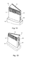
- FIG 1 is a principle sketch showing a plug 10 for cooperation with a connector 40.
- the plug 10 may have a first part 11 for insertion into a corresponding receptive part of the connector 40, and a second part 12 constituting a handle part for handling the plug 10, e.g. when inserting or removing the plug 10.
- the plug 10 is shown having a generally triangular cross-section.
- the receptive part of the connector 40 correspondingly must have a generally triangular cross-section.
- the cross-section being triangular will provide the plug and connector with a keying function that is beneficial in relation to the correct insertion of the plug 10.
- the triangular cross-sectional shape is only exemplary. Any other distinct shape allowing only one way of inserting the plug 10 into the connector 20 can be applied. However, the plug can also have any traditional shape without the keying function.
- the plug 10 is provided with a plurality of electrical contacts 13 adapted to cooperate with corresponding contacts (not shown) in the connector 40.
- These contacts 13 are arranged on the first part 11, and are adapted to transfer electronic data.
- the capacity of the plug 10 to transfer data depends on the number of contacts 13.
- the plug 10 On at least one of its side surfaces 15, the plug 10 is provided with one or more indentations 20 constituting a receiving part of a combined locking and data/energy transmitting mechanism.
- indentations 20 can be elongated grooves.
- the indentations 20 can have other shapes as well, e.g. circular.
- electrical conductors 16 terminating at the bottom face 22 of the indentations. These electrical conductors 16 are adapted to transfer energy or data in an electrical form between the plug 10 to the connector 40.
- the connector 40 has a receiving part (not shown) in the form of a recess having the same cross sectional form as the insertion part 11 of plug 10, and being adapted to receive part 11.
- a plurality of electrical contacts are provided, corresponding to the plurality of contacts 13 on the plug 10.
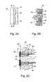
- the connector 40 has one or more recesses 41 adapted for holding pogo pin-like conductive, resilient means; the resilient means 30 constituting the connector parts of the locking mechanism corresponding to the indentations 20 in the plug 10.
- the resilient means 30 comprises a tap 31 and a helical spring 37 having a first end 38 and a second end 39.
- the first end 38 of the helical spring 37 is connected to the tap 31 and the second end 39 is connected to the bottom 42 of the recess 41.
- the helical spring may be replaced by other suitable resilient means.
- the helical spring 37 is preferably made from or coated with an electrically conductive material.
- electrical conductors 46 terminating at the bottom face 42 of the recesses 41. These electrical conductors 46 are adapted to transfer energy or data in an electrical form between the plug 10 to the connector 40.
- the tap 31 has a front surface 33 and at least one side surface 34 and a flange 35 having a circumference greater than that of a cross section through the tap 31, i.e. the flange 35 extends beyond the side walls 34 of the tap 31.
- the passages/transitions 32 from the front surface 33 to the side surfaces 34 of the plug along the edges or at least the corners of surface 33 are smooth or rounded corresponding to the passages/transitions 22 of the plug 10.
- the recess 41 and the pogo pin 30 are shown in greater detail to illustrate the function of the flange 35.
- the flange 35 is adapted to cooperate with a groove 43 in the recess 41, the groove 43 providing a forward stopping surface 44 and a backward stopping surface 45 for the tap 31.
- the tap 31 is fitted inside and adapted to slide within the recess 41 in the connector 40 between extreme positions defined by the stopping surfaces 44 and 45 of the groove 43.
- the circumference of the flange 35 corresponds to the inner circumference of the groove 43.
- the tap 31 is shown in its most advanced position; the flange 35 of the tap abutting the forward stopping surface 44 of the groove 43.
- the helical spring 37 is adapted to urge the tap 31 to remain in this advanced position.
- the front surface 33 of the tap 31 will extend beyond the plane of the wall 47 of the connector 40.
- the front surface 33 of the tap is aligned or retracted to a position behind the plane of the wall 47 of the connector.
- the side wall of the plug 10 When the insertion part 11 of the plug 10 is inserted into the connector 40 the side wall of the plug 10 will initially abut the taps 31. When the insertion part 11 is advanced further the rounded passages/transitions 32 of the taps 31 will allow the insertion part 11 to push the taps 31 towards their retracted position, against the force of the helical spring 37, and allow the insertion part to pass the taps 31. In the fully inserted position of the plug 10, the taps 31 will be aligned with the indentations 20 on the plug 10, the spring urging the taps 31 towards its forward position, locking the taps 31 into the indentations 20. Thus the plug 10 will be locked to the connector 40.
- the conductor 46, the helical spring 37, and the tap 31 of the locking mechanism are formed in a conductive material or they are coated with a conductive material and all the said parts 46, 37, 31 are electronically interconnected.
- the conductor 16 and the at least part of the inside walls 23 of the indentation 20 are formed in a conductive material or they are coated with a conductive material, and all the said parts 16, 23 are electronically interconnected.
- a gold plating could e.g. constitute the coating of all or some of the parts of the locking mechanisms.
- all or some of the parts of the locking mechanisms could be formed in a conductive material, such as a metal.
- the plug 10 is equipped with two indentations 20 on each of two opposite parallel side surfaces 15.
- the connector will be equipped with two pairs of corresponding resilient means 30.
- the locking mechanism will provide the connection of the plug 10 and connector 40 with a stable grip on each other, as well as four additional contacts.
- the plug 10 and connector 20 could be equipped with any desired number of pairs of resilient means 30 and indentations 20, depending on the size of the plug/connector and/or the size of the locking mechanisms.
- the additional contacts provided by the locking mechanism can be used for transferring data, or they can be used for transferring electrical energy, e.g. for charging the battery of an electrical equipment. Alternatively, some of the additional contacts can be used to transfer energy and some for transferring data.
- resilient means 30 could be placed on the plug 10 and the indentations 20 on the connector.
- the plug 10 or the connector 40 could be an integrated part of an electronic equipment, e.g. a mobile/cell phone.
- the corresponding part could be a separate part connected via a cord to another electronic equipment, e.g. a computer, or it could be an integrated part of another electronic equipment.
Landscapes
- Details Of Connecting Devices For Male And Female Coupling (AREA)
Priority Applications (1)
| Application Number | Priority Date | Filing Date | Title |
|---|---|---|---|
| EP03388072A EP1530267A1 (en) | 2003-11-07 | 2003-11-07 | Electronic connection device for transferring energy and data |
Applications Claiming Priority (1)
| Application Number | Priority Date | Filing Date | Title |
|---|---|---|---|
| EP03388072A EP1530267A1 (en) | 2003-11-07 | 2003-11-07 | Electronic connection device for transferring energy and data |
Publications (1)
| Publication Number | Publication Date |
|---|---|
| EP1530267A1 true EP1530267A1 (en) | 2005-05-11 |
Family
ID=34429599
Family Applications (1)
| Application Number | Title | Priority Date | Filing Date |
|---|---|---|---|
| EP03388072A Withdrawn EP1530267A1 (en) | 2003-11-07 | 2003-11-07 | Electronic connection device for transferring energy and data |
Country Status (1)
| Country | Link |
|---|---|
| EP (1) | EP1530267A1 (no) |
Citations (6)
| Publication number | Priority date | Publication date | Assignee | Title |
|---|---|---|---|---|
| US2306206A (en) * | 1940-08-13 | 1942-12-22 | Pye Ltd | Electric coupling |
| FR2402317A1 (fr) * | 1977-08-30 | 1979-03-30 | Voegtlin Jacques | Prise de courant |
| JPH0414779A (ja) * | 1990-05-02 | 1992-01-20 | Fujikura Ltd | 低挿入力コネクタ |
| DE9307819U1 (de) * | 1993-05-24 | 1993-08-12 | Gebauer, Detlev, 75233 Tiefenbronn | Anordnung zum elektrischen Verbinden von zwei Bauteilen |
| US5772461A (en) * | 1996-09-13 | 1998-06-30 | Hon Hai Precision Ind. Co., Ltd. | Locking mechanism for interconnecting two mated connectors |
| EP1329991A1 (en) * | 2000-10-26 | 2003-07-23 | Shin-Etsu Polymer Co., Ltd. | Press contact clamping connector and its connection structure |
-
2003
- 2003-11-07 EP EP03388072A patent/EP1530267A1/en not_active Withdrawn
Patent Citations (6)
| Publication number | Priority date | Publication date | Assignee | Title |
|---|---|---|---|---|
| US2306206A (en) * | 1940-08-13 | 1942-12-22 | Pye Ltd | Electric coupling |
| FR2402317A1 (fr) * | 1977-08-30 | 1979-03-30 | Voegtlin Jacques | Prise de courant |
| JPH0414779A (ja) * | 1990-05-02 | 1992-01-20 | Fujikura Ltd | 低挿入力コネクタ |
| DE9307819U1 (de) * | 1993-05-24 | 1993-08-12 | Gebauer, Detlev, 75233 Tiefenbronn | Anordnung zum elektrischen Verbinden von zwei Bauteilen |
| US5772461A (en) * | 1996-09-13 | 1998-06-30 | Hon Hai Precision Ind. Co., Ltd. | Locking mechanism for interconnecting two mated connectors |
| EP1329991A1 (en) * | 2000-10-26 | 2003-07-23 | Shin-Etsu Polymer Co., Ltd. | Press contact clamping connector and its connection structure |
Non-Patent Citations (1)
| Title |
|---|
| PATENT ABSTRACTS OF JAPAN vol. 016, no. 166 (E - 1193) 22 April 1992 (1992-04-22) * |
Similar Documents
| Publication | Publication Date | Title |
|---|---|---|
| US10401905B2 (en) | Slide dock and methods of making and using | |
| US5885088A (en) | Electrical connector assembly with polarization means | |
| US20100190384A1 (en) | Key coded power adapter connectors | |
| US4820169A (en) | Programmable modular connector assembly | |
| US7607920B1 (en) | Connecting device for interconnecting electronic devices | |
| US6309255B1 (en) | Electrical connector having power contacts for providing high electrical power | |
| CN102570189B (zh) | 用于大形状系数功率连接器的活动接地销针 | |
| US11296457B2 (en) | Magnetic connector | |
| CN100420100C (zh) | 可安装在电路板上的连接器组合 | |
| EP3210262A1 (en) | Connectors with movable magnetic components and method of connecting devices | |
| EP1064703A1 (en) | Type iii pcmcia card with integrated receptacles for receiving standard communications plugs | |
| CA2897317C (en) | User configurable connector | |
| US6033240A (en) | Retractable media jack operable with two discrete media connectors | |
| EP2259389A2 (en) | Electrical Connector with a resilient latching rod | |
| CN210404181U (zh) | 电连接器 | |
| US5989051A (en) | Connector for joining a cable to a PCMCIA card | |
| CN209217329U (zh) | 快速连接器 | |
| CN218242503U (zh) | 一种转接件 | |
| CN203607633U (zh) | 具有防呆功能的磁吸式电连接装置 | |
| CN217134710U (zh) | 连接器 | |
| US7077690B2 (en) | Electrical connector with improved slider member | |
| US20090113103A1 (en) | Cascade type charge assembly | |
| TWM583645U (zh) | 多國充電器結構 | |
| CN209948281U (zh) | 一种分体式数据线 | |
| US8602824B2 (en) | Ultrathin USB female connector |
Legal Events
| Date | Code | Title | Description |
|---|---|---|---|
| PUAI | Public reference made under article 153(3) epc to a published international application that has entered the european phase |
Free format text: ORIGINAL CODE: 0009012 |
|
| AK | Designated contracting states |
Kind code of ref document: A1 Designated state(s): AT BE BG CH CY CZ DE DK EE ES FI FR GB GR HU IE IT LI LU MC NL PT RO SE SI SK TR |
|
| AX | Request for extension of the european patent |
Extension state: AL LT LV MK |
|
| 17P | Request for examination filed |
Effective date: 20051103 |
|
| AKX | Designation fees paid |
Designated state(s): AT BE BG CH CY CZ DE DK EE ES FI FR GB GR HU IE IT LI LU MC NL PT RO SE SI SK TR |
|
| STAA | Information on the status of an ep patent application or granted ep patent |
Free format text: STATUS: THE APPLICATION IS DEEMED TO BE WITHDRAWN |
|
| 18D | Application deemed to be withdrawn |
Effective date: 20060807 |