EP1530164A2 - X-ray CT image production method and X-ray CT system - Google Patents
X-ray CT image production method and X-ray CT system Download PDFInfo
- Publication number
- EP1530164A2 EP1530164A2 EP04256828A EP04256828A EP1530164A2 EP 1530164 A2 EP1530164 A2 EP 1530164A2 EP 04256828 A EP04256828 A EP 04256828A EP 04256828 A EP04256828 A EP 04256828A EP 1530164 A2 EP1530164 A2 EP 1530164A2
- Authority
- EP
- European Patent Office
- Prior art keywords
- projection data
- ray
- image
- data items
- reconstruction
- Prior art date
- Legal status (The legal status is an assumption and is not a legal conclusion. Google has not performed a legal analysis and makes no representation as to the accuracy of the status listed.)
- Withdrawn
Links
Images






Classifications
-
- A—HUMAN NECESSITIES
- A61—MEDICAL OR VETERINARY SCIENCE; HYGIENE
- A61B—DIAGNOSIS; SURGERY; IDENTIFICATION
- A61B6/00—Apparatus or devices for radiation diagnosis; Apparatus or devices for radiation diagnosis combined with radiation therapy equipment
- A61B6/02—Arrangements for diagnosis sequentially in different planes; Stereoscopic radiation diagnosis
- A61B6/03—Computed tomography [CT]
-
- G—PHYSICS
- G06—COMPUTING OR CALCULATING; COUNTING
- G06T—IMAGE DATA PROCESSING OR GENERATION, IN GENERAL
- G06T12/00—Tomographic reconstruction from projections
- G06T12/20—Inverse problem, i.e. transformations from projection space into object space
-
- A—HUMAN NECESSITIES
- A61—MEDICAL OR VETERINARY SCIENCE; HYGIENE
- A61B—DIAGNOSIS; SURGERY; IDENTIFICATION
- A61B6/00—Apparatus or devices for radiation diagnosis; Apparatus or devices for radiation diagnosis combined with radiation therapy equipment
- A61B6/02—Arrangements for diagnosis sequentially in different planes; Stereoscopic radiation diagnosis
- A61B6/03—Computed tomography [CT]
- A61B6/032—Transmission computed tomography [CT]
-
- G—PHYSICS
- G06—COMPUTING OR CALCULATING; COUNTING
- G06T—IMAGE DATA PROCESSING OR GENERATION, IN GENERAL
- G06T12/00—Tomographic reconstruction from projections
- G06T12/10—Image preprocessing, e.g. calibration, positioning of sources or scatter correction
-
- A—HUMAN NECESSITIES
- A61—MEDICAL OR VETERINARY SCIENCE; HYGIENE
- A61B—DIAGNOSIS; SURGERY; IDENTIFICATION
- A61B6/00—Apparatus or devices for radiation diagnosis; Apparatus or devices for radiation diagnosis combined with radiation therapy equipment
- A61B6/02—Arrangements for diagnosis sequentially in different planes; Stereoscopic radiation diagnosis
- A61B6/027—Arrangements for diagnosis sequentially in different planes; Stereoscopic radiation diagnosis characterised by the use of a particular data acquisition trajectory, e.g. helical or spiral
-
- Y—GENERAL TAGGING OF NEW TECHNOLOGICAL DEVELOPMENTS; GENERAL TAGGING OF CROSS-SECTIONAL TECHNOLOGIES SPANNING OVER SEVERAL SECTIONS OF THE IPC; TECHNICAL SUBJECTS COVERED BY FORMER USPC CROSS-REFERENCE ART COLLECTIONS [XRACs] AND DIGESTS
- Y10—TECHNICAL SUBJECTS COVERED BY FORMER USPC
- Y10S—TECHNICAL SUBJECTS COVERED BY FORMER USPC CROSS-REFERENCE ART COLLECTIONS [XRACs] AND DIGESTS
- Y10S378/00—X-ray or gamma ray systems or devices
- Y10S378/901—Computer tomography program or processor
Definitions
- the present invention relates to an X-ray computed tomography (CT) image production method and an X-ray CT system. More particularly, the present invention is concerned with an X-ray CT image production method and an X-ray CT system that reconstruct an image by utilizing a plurality of projection data items acquired with X-rays which pass through the same pixel location in the same scan field while being transmitted along different paths with a scanner gantry set at the same view angle or an opposite view angle.
- CT computed tomography
- X-ray CT systems are known (refer to, for example, Japanese Unexamined Patent Application Publication No. 2003-159244)to be such that: projection data is acquired while an X-ray tube and a multi-channel detector are rotated about a subject and a tabletop on which the subject lies down is rectilinearly moved; projection data items acquired with X-rays that pass through a pixel location in a scan field are sampled in order to produce a data set that is used to reconstruct a CT image expressing the scan field; and a CT image is then reconstructed based on the data set.
- a helical scan is performed using a multi-channel detector
- a plurality of projection data items is acquired using X-rays that pass through the same pixel location in the same scan field while being transmitted along different paths with a scanner gantry set at the same view angle.
- the conventional X-ray CT system does not utilize the plurality of projection data items but samples one projection data instead of projection data items that are acquired with the scanner gantry set at a certain view angle, and uses the sampled projection data to reconstruct an image.
- an object of the present invention is to provide an X-ray CT image production method and an X-ray CT system that reconstruct an image by utilizing a plurality of projection data items acquired using X-rays which pass through the same pixel location in the same scan field while being transmitted along different paths at a scanner gantry set at the same view angle or an opposite view angle.
- an X-ray CT image production method while at least one of an X-ray tube and a multi-channel detector is relatively rotated about a subject and the subject is relatively rectilinearly moved, projection data is acquired. Two or more projection data items acquired with X-rays that pass through the same pixel location in a scan field while being transmitted along different paths with a scanner gantry set at the same view angle or an opposite view angle are synthesized in order to produce reconstruction projection data relevant to the view angle. A CT image is then reconstructed based on the reconstruction projection data.
- a plurality of projection data items acquired with X-rays that pass through a pixel location in a scan field while being transmitted along different paths with the scanner gantry set at the same view angle or an opposite view angle is sampled from among all projection data items acquired by performing a helical scan using the multi-channel detector.
- the sampled projection data items are synthesized in order to produce reconstruction projection data.
- a CT image is reconstructed based on a data set comprising reconstruction projection data items relevant to all view angles needed to reconstruct CT images. Consequently, pieces of information acquired along the two or more paths along which X-rays are transmitted are reflected on data relevant to one view angle.
- the shape of the subject can be reproduced accurately. Moreover, since the reproduction of the shape brings about little contradiction, artifact can be reduced. Furthermore, since an amount of information increases, a signal-to-noise ratio improves.
- an X-ray CT image production method identical to the foregoing X-ray CT image production method except that two or more projection data items are weighted and summated in order to product the reconstruction projection data.
- two or more projection data items are weighted and summated for synthesis in order to produce one reconstruction projection data.
- the quality of an CT image can be adjusted by changing the weights that are used for the weighting and summation.
- an X-ray CT image production method identical to the foregoing X-ray CT image production method except that as the distances from detector arrays, which detect two or more projection data items respectively, to the scan field is shorter, the weights to be used for the weighting and summation are made larger.
- the weights to be applied to the projection data items are made larger. If the detector arrays are located far from the scan field, the weights to be applied to the projection data items are made smaller. Consequently, the quality of a CT image can be improved without being changed largely.
- an X-ray CT image production method that is identical to the foregoing X-ray CT image production method except that an operator can designate the weights that are used for the weighting and summation.
- an operator can change the weights that are used for the weighting and summation and can eventually adjust the quality of a CT image.
- an X-ray CT image production method that is identical to the foregoing X-ray CT image production method except that an operator can designate the number of projection data items N that is larger than 2.
- an operator can change the number of projection data items N that is larger than 2, and can eventually adjust the quality of a CT image.
- an X-ray CT image production method in which: while at least one of an X-ray tube and a multi-channel detector is relatively rotated about a subject and the subject is relatively rectilinearly moved, projection data is acquired; two or more data sets are produced in order to reconstruct a CT image expressing a scan field; two or more CT images are then reconstructed based on the two or more data sets; and the CT images are synthesized to produce a synthetic CT image.
- a plurality of projection data items acquired with X-rays that pass through a pixel location in a scan field while being transmitted along different paths with a scanner gantry set at the same view angle or an opposite view angle is sampled from among all projection data items acquired by performing a helical scan using the multi-channel detector.
- Data sets containing the respective projection data items are produced.
- CT images are reconstructed based on the respective data sets, and synthesized in order to construct a synthetic CT image. Consequently, since pieces of information acquired along two or more paths along which X-rays are transmitted are reflected on data relevant to one view angle, the shape of the subject can be reproduced accurately. Moreover, since the reproduction of the shape brings about little contradiction, artifact can be reduced. Furthermore, since an amount of information increases, a signal-to-noise ratio improves.
- an X-ray CT image production method identical to the aforesaid X-ray CT image production method except that two or more CT images are weighted and summated in order to construct the synthetic CT image.
- two or more CT images are weighted and summated for synthesis in order to construct a new CT image.
- the quality of the new CT image can be adjusted by changing the weights to be used for the weighting and summation.
- an X-ray CT image production method identical to the foregoing X-ray CT image production method except that as the distances from detector arrays, via which the data sets are produced, to the scan field is shorter, the weights to be used for the weighting and summation are made larger.
- the detector arrays via which the data sets are produced are located closely to the scan field, the weights to be applied to the projection data items are increased. If the detector arrays are located far away, the weights are decreased. Consequently, the quality of a CT image can be improved without being drastically changed.
- an X-ray CT image production method identical to the foregoing X-ray CT image production method except that an operator can designate the weights to be used for the weighting and summation.
- an operator can change the weights to be used for the weighting and summation and can eventually adjust the quality of a CT image.
- an X-ray CT image production method identical to the foregoing X-ray CT image production method except that an operator can designate the number of data sets N that is larger than 2.
- an operator can change the number of data sets N that is larger than 2 and can eventually adjust the quality of a CT image.
- an X-ray CT system comprising: an X-ray tube; a multi-channel detector; a helical scan means for acquiring projection data while relatively rotating at least one of the X-ray tube and multi-channel detector about a subject and relatively rectilinearly moving the subject; a reconstruction projection data production means for synthesizing two or more projection data items acquired with X-rays that pass through the same pixel location in a scan field while being transmitted along different paths with a scanner gantry set at the same view angle or an opposite view angle, and thus producing reconstruction projection data relevant to the view angle; and an image reconstruction means for reconstructing a CT image on the basis of the reconstruction projection data.
- the X-ray CT image production method in accordance with the first aspect can be implemented.
- an X-ray CT system identical to the foregoing X-ray CT system except that the reconstruction projection data production means weights and summates the two or more projection data items so as to produce the reconstruction projection data.
- the X-ray CT image production method in accordance with the second aspect can be implemented.
- an X-ray CT system identical to the foregoing X-ray CT system except that the reconstruction projection data production means makes the weights, which are used for the weighting and summation, larger as the distances from detector arrays, which detect the two or more projection data items, to the scan field are shorter.
- the X-ray CT image production method in accordance with the third aspect can be implemented.
- an X-ray CT system identical to the foregoing X-ray CT system except that a designation means is included for allowing an operator to designate the weights to be used for the weighting and summation.
- the X-ray CT image production method in accordance with the fourth aspect can be implemented.
- an X-ray CT system identical to the foregoing X-ray CT system except that a designation means is included for allowing an operator to designate the number of projection data items N which is larger than 2.
- the X-ray CT image production method in accordance with the fifth aspect can be implemented.
- an X-ray CT system comprising: an X-ray tube; a multi-channel detector; a helical scan means for acquiring projection data while relatively rotating at least one of the X-ray tube and multi-channel detector about a subject and relatively rectilinearly moving the subject; a data set production means for producing two or more data sets that are used to reconstruct CT images expressing a scan field; an image reconstruction means for reconstructing two or more CT images on the basis of the two or more data sets; and an image synthesis means for synthesizing the CT images to construct a synthetic CT image.
- the X-ray CT image production method in accordance with the sixth aspect can be implemented.
- an X-ray CT system identical to the foregoing X-ray CT system except that the image synthesis means weights and summates the two or more CT images so as to construct the synthetic CT image.
- the X-ray CT image production method in accordance with the seventh aspect can be implemented.
- an X-ray CT system identical to the foregoing X-ray CT system except that as the distances from detector arrays, via which the data sets are produced, to the scan field are shorter, the weights to be used for the weighting and summation are made larger.
- the X-ray CT image production method in accordance with the eighth aspect can be implemented.
- an X-ray CT system identical to the foregoing X-ray CT system except that a designation means is included for allowing an operator to designate the weights to be used for the weighting and summation.
- the X-ray CT image production method in accordance with the ninth aspect can be implemented.
- an X-ray CT system identical to the foregoing X-ray CT system except that a designation means is included for allowing an operator to designate the number of data sets N that is larger than 2.
- the X-ray CT image production method in accordance with the tenth aspect can be implemented.
- the shape of a subject can be accurately reproduced and artifact can be reduced. Moreover, a signal-to-noise ratio can be improved.
- An X-ray CT image production method and an X-ray CT system in accordance with the present invention can be used to produce a high-quality X-ray CT image.
- Fig. 1 is a block diagram showing the configuration of an X-ray CT system in accordance with the first embodiment.
- An X-ray CT system 100 comprises an operator console 1, a patient couch 10, and a scanner gantry 20.
- the operator console 1 comprises: an input device 2 that receives an operator's entry; a central processing unit 3 that executes image reconstruction and others; a data acquisition buffer 5 in which projection data acquired by the scanner gantry 20 is stored; a CRT 6 on which a CT image reconstructed based on the projection data is displayed; and a storage device 7 in which programs, data, and X-ray CT images are stored.
- the patient couch 10 includes a tabletop 12 that is inserted into or withdrawn from a bore of the scanner gantry 20 with a subject lying down thereon.
- the tabletop 12 is lifted or lowered or rectilinearly moved by a motor incorporated in the patient couch 10.
- the scanner gantry 20 accommodates an X-ray tube 21, an X-ray controller 22, a collimator 23, a multi-channel detector 24, a data acquisition system (DAS) 25, a collimator 23, a rotation controller 26 for controlling the DAS 25, and a control unit 29 that communicates control signals or the like to or from the operator console 1 and patient couch 10, and a slip ring 30.
- DAS data acquisition system
- the scanner gantry 20 accommodates an X-ray tube 21, an X-ray controller 22, a collimator 23, a multi-channel detector 24, a data acquisition system (DAS) 25, a collimator 23, a rotation controller 26 for controlling the DAS 25, and a control unit 29 that communicates control signals or the like to or from the operator console 1 and patient couch 10, and a slip ring 30.
- DAS data acquisition system
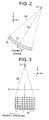
- Fig. 2 and Fig. 3 are explanatory diagrams concerning the X-ray tube 21 and multi-channel detector 24.
- the X-ray tube 21 and multi-channel detector 24 rotate about a center of rotation IC.
- the direction of rectilinear movement made by the tabletop 12 shall be a z-axis direction, and the direction perpendicular to the top of the tabletop 12 shall be a y-axis direction, and the direction perpendicular to the z-axis direction and y-axis direction alike shall be an x-axis direction.
- the X-ray tube 21 and multi-channel detector 24 rotate on an xy plane.
- the X-ray tube 21 generates an X-ray beam CB that is a conical beam.
- a view angle view shall be 0°.
- the multi-channel detector 24 has, for example, 256 detector arrays.
- the detector arrays provide, for example, 1024 channels.
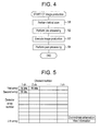
- Fig. 4 is a flowchart describing actions to be performed in the X-ray CT system 100.
- step S1 the X-ray tube 21 and multi-channel detector 24 are rotated about a subject and the tabletop 12 is moved rectilinearly. Meanwhile, projection data DO(a,view,j,i) identified with a rectilinear movement end position z, a view angle view, a detector array number j, and a channel number i is acquired.
- an encoder is used to count the number of pulses.
- the control unit 29 converts the count value into a z-coordinate. Eventually, z-coordinate information is appended to projection data acquired by the DAS 25 via the slip ring 30.
- Fig. 5 shows the structure of projection data acquired at a certain view angle view.
- pre-processing (offset correction, logarithm correction, X-ray dose correction, and sensitivity correction) is performed on the projection data D0(z,view,j,i).
- a CT image is produced based on the pre-processed projection data D0(z,view,j,i). The image production will be detailed later.
- the produced CT image is post-processed so that it can be appropriately displayed.
- Fig. 6 is a flowchart describing the image production (step S3).
- a view angle is selected from among all view angles within a view range needed for image reconstruction (for example, 180° + angle of a fan beam).
- one pixel location is selected from among all pixel locations in a scan field.
- N ( ⁇ 2) projection data items acquired with X-rays that pass through the selected pixel location while being transmitted along different paths with the scanner gantry set at the selected view angle or an opposite view angle are sampled from among all projection data items acquired by performing a helical scan.
- the sampled N projection data items are synthesized in order to produce reconstruction projection data.
- the z-coordinate or the position in the z-axis direction that helps identify reconstruction projection data shall be the position in the z-axis direction at which the X-ray tube is located when projection data is detected by a detector array out of the detector arrays, which detect the plurality of projection data items, whose distance from the scan field P is the shortest.
- an operator can use the input device 2 to change the setting of the number of projection data items to be synthesized N or the settings of the weights with which the N projection data items are weighted before they are summated.
- steps W2 and W3 are repeated relative to all pixel locations in the scan field.
- steps W1 to W4 are repeated relative to all view angles needed for image reconstruction.
- a CT image is reconstructed based on a data set comprising reconstruction projection data items relevant to all view angles needed for image reconstruction.
- An image reconstruction method to be adopted at this time may be a two-dimensional image reconstruction method or a three-dimensional image reconstruction method such as the Feldkamp method or the weighted Feldkamp method.
- the shape of a subject can be reproduced accurately. Moreover, since the reproduction of the shape brings about little contradiction, artifact can be reduced. Furthermore, since an amount of information increases, a signal-to-noise ratio improves.
- Image production described in Fig. 8 may be executed as step S3 in Fig. 4.
- the image production described in Fig. 8 shall be called three-dimensional back projection.
- a view angle is selected from among all view angles within a view range needed for image reconstruction.
- a line is selected from among a plurality of parallel lines spaced from one another by a length equivalent to a plurality of pixel locations in the scan field P.
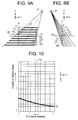
- Fig. 9 shows an example of a plurality of parallel lines L0 to L8 in the scan field P.
- the number of lines is a 1/64 to a 1/2 of the largest number of pixel locations in the scan field P in a direction orthogonal to the lines. For example, when the number of pixel locations in the scan field P is a product of 512 by 512, the number of lines is nine.
- the x-axis direction shall be the direction of lines.
- the view angle is equal to or larger than 45° and smaller than 135° (or falls within a range centered on the range of view angles) or when the view angle is equal to or larger than 225° and smaller than 315° (or falls within a range centered on the range of view angles)
- the y-axis direction shall be the direction of lines.
- the position of the X-ray tube 21 in Fig. 9 shall correspond to the position thereof shown in Fig. 7(d).
- a projection plane pp shall be parallel to the lines L0 to L8 and passes through the center of rotation IC.
- N projection data items acquired from a selected line along different paths, along which X-rays being transmitted, with the scanner gantry set at a selected view angle are sampled.
- the N sampled projection data items that have been acquired from the selected line are synthesized in order to produce reconstruction projection data representing the selected line.
- Fig. 10 shows a line T0 defined on a detector surface dp by projecting the line L0 in the scan field P in an X-ray transmitting direction, in which X-rays are transmitted, with the X-ray tube 21 located at the position shown in Fig. 7(d).
- the X-ray transmitting direction in which X-rays are transmitted is determined with the geometric positions of the X-ray tube 21, multi-channel detector 24, and line L0.
- lines T0 are defined on the detector surface dp accordingly.
- Projection data items acquired with the scanner gantry set at the selected view angle are extracted from the detector elements identified with the detector array numbers and channel numbers indicated with the lines T0.
- N projection data items acquired from the selected line can be extracted.
- the N projection data items extracted from the same channels are weighted and summated in the same manner as those in the first embodiment.
- reconstruction projection data representing one selected line and being produced based on the projection data items acquired with the scanner gantry set at the selected view angle is produced.
- Adopted as the position of a line defined on the detector surface dp in order to produce the reconstruction projection data is the position of a line located most closely to the scan field P among all the lines T0 defined with the plurality of projection data items.
- An operator can use the input device 2 to change the setting of the number of projection data items to be synthesized N or the settings of the weights by which the N projection data items are weighted before summated.
- steps R2 to R3 are repeated relative to all lines.
- Fig. 11 shows lines T0 to T8 defined on the detector surface dp by projecting the lines L0 to L8 in order to produce reconstruction projection data items.
- reconstruction projection data items produced from projection data items indicated with the lines T0 to T8 on the detector surface dp are developed as reconstruction projection data items Dr in the X-ray transmitting direction in order to define lines L0' to L8' on the projection plane pp.
- the reconstruction projection data items Dr indicated with the lines L0' to L8' on the projection plane pp are multiplied by conical beam reconstruction weights determined for reconstructing an image using a conical beam. This results in projection line data items Dp developed on the projection plane pp as shown in Fig. 13.
- the conical beam reconstruction weights are expressed as (r1/r0) 2 where r0 denotes the distance from the focal spot in the X-ray tube 21 to a detector element in the multi-channel detector 24 which is identified with a detector array number j and a channel number i and from which reconstruction projection data Dr is extracted, and r1 denotes the distance from the focal spot in the X-ray tube 21 to a point in the scan field P represented by the reconstruction projection data Dr.
- the projection line data items Dp developed on the projection plane pp are filtered. Specifically, the projection line data items Dp on the projection plane pp are fast-Fourier-transformed, multiplied by a filtering function (reconstruction function), and inverse-fast-Fourier-transformed. This results in back projection line data items Df developed on the projection plane pp as shown in Fig. 14.
- step R8 the back projection line data items Df on the projection plane pp are interpolated in the direction of lines. This results in high-density back projection line data items Dh developed on the projection plane pp as shown in Fig. 15.
- the density of the high-density back projection line data items Dh on the projection plane pp is equivalent to an 8 to 32 multiple of the largest number of pixel locations in the scan field P in the direction of lines. For example, when the largest number of pixels in the scan field P is a product of 512 by 512, if the density of data items is a 16 multiple of the largest number of pixels, the density is 8192 points per line.
- step R9 the high-density back projection line data items Dh developed on the projection plane pp are sampled and, if necessary, interpolated or extrapolated. This results in back projection pixel data items D2 representing the pixel locations on the lines L0 to L8 in the scan field P.
- the high-density back projection line data items Dh developed on the projection plane pp are sampled and interpolated or extrapolated. This results in back projection pixel data items D2 representing the pixel locations on the lines L0 to L8. Otherwise, based on the back projection pixel data items D2 representing the pixel locations on the lines L0 to L8, projection data items acquired from the scan field P may be interpolated or extrapolated in order to produce back projection pixel data items D2 representing the pixel locations among the lines L0 to L8.
- Fig. 12 to Fig. 17 show an image reconstruction procedure on the assumption that the view angle is equal to or larger than - 45° and smaller than 45° (or falls within a range centered on the range of view angles) or equal to or larger than 135° and smaller than 225° (or falls within a range centered on the range of view angles).
- the view angle is equal to or larger than 45° and smaller than 135° (or falls within a range centered on the range of view angles) or equal to or larger than 225° and smaller than 315° (or falls within a range centered on the range of view angles)
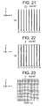
- an image reconstruction procedure shown in Fig. 18 to Fig. 23 is adopted.
- an angle at which a line meets the X-ray transmitting direction will not be smaller than approximately 45°.
- deterioration in precision can be suppressed (if a line in the scan field P is projected in the X-ray transmitting direction, as the angle at which the line meets the X-ray transmitting direction is closer to 90°, precision improves. As the angle at which the line meets the X-ray transmitting direction is closer to 0°, precision is degraded).
- back projection pixel data items D2 shown in Fig. 17 or Fig. 23 are summated pixel location by pixel location.
- steps R1 to R11 are repeated relative to all view angles needed for image reconstruction. This results in back projection data items D3(x,y).
- the shape of a subject can be accurately reproduced. Moreover, since the reproduction of the shape brings about little contradiction, artifact can be reduced. Moreover, since an amount of information increases, a signal-to-noise ratio improves. Furthermore, complicated arithmetic and logic operations must be performed merely on projection data items acquired from the lines L0 to L8 in the scan field P. Consequently, the number of arithmetic and logic operations to be performed can be largely reduced.
- projection data items acquired with the scanner gantry set at the same view angle are synthesized in order to produce reconstruction projection data items.
- projection data items acquired with the scanner gantry set at an opposite view angle may be synthesized in order to product reconstruction projection data items.
- projection data items are synthesized.
- CT images may be synthesized.
- Fig. 25 is a flowchart describing image production employed in the fourth embodiment.
- N data sets that are used to reconstruct CT images expressing the scan field P are produced from projection data items acquired along paths along which X-rays are transmitted and some or all of which are different from one another.
- a first data set is produced from projection data items acquired by rotating the scanner gantry from the state attained with a view angle of 0° as shown in Fig. 7(a) to the state attained with a view angle of 360° as shown in Fig. 7(b).
- a second data set is produced from projection data items acquired by rotating the scanner gantry from the state attained with the view angle of 360° as shown in Fig. 7(b) to the state attained with a view angle of 720° as shown in Fig. 7(c).
- a third data set is produced from projection data items acquired by rotating the scanner gantry from the state attained with the view angle of 720° as shown in Fig. 7(c) to the state attained with a view angle of 1080° as shown in Fig. 7(d).
- An operator can use the input device 2 to change the setting of the number of data sets N.
- a certain data set is selected.
- a CT image is reconstructed based on the selected data set.
- steps V2 and V3 are repeated relative to all data sets.
- CT images reconstructed based on all the data sets are weighted and summated in order to construct a new CT image.
- an operator can use the input device 2 to change the settings of N weights used to weight respective CT images before summation.
- the shape of a subject can be accurately reproduced. Moreover, since the reproduction of the shape brings about little contradiction, artifact can be reduced. Moreover, since an amount of information increases, a signal-to-noise ratio improves. Furthermore, a plurality of CT images expressing the same scan field P can be reconstructed simultaneously.
Landscapes
- Engineering & Computer Science (AREA)
- Health & Medical Sciences (AREA)
- Life Sciences & Earth Sciences (AREA)
- Physics & Mathematics (AREA)
- Medical Informatics (AREA)
- Theoretical Computer Science (AREA)
- General Physics & Mathematics (AREA)
- Heart & Thoracic Surgery (AREA)
- Biomedical Technology (AREA)
- Biophysics (AREA)
- Nuclear Medicine, Radiotherapy & Molecular Imaging (AREA)
- Optics & Photonics (AREA)
- Pathology (AREA)
- Radiology & Medical Imaging (AREA)
- High Energy & Nuclear Physics (AREA)
- Veterinary Medicine (AREA)
- Molecular Biology (AREA)
- Surgery (AREA)
- Animal Behavior & Ethology (AREA)
- General Health & Medical Sciences (AREA)
- Public Health (AREA)
- Pulmonology (AREA)
- Apparatus For Radiation Diagnosis (AREA)
Abstract
Description
Claims (10)
- An X-ray CT image production method, comprising the steps of:acquiring projection data while relatively rotating at least one of an X-ray tube (21) and a multi-channel detector (24) about a subject and relatively rectilinearly moving the subject;synthesizing two or more projection data items, which are acquired with X-rays that pass through the same pixel location in a scan field while being transmitted along different paths with a scanner gantry set at the same view angle or an opposite view angle, so as to produce reconstruction projection data relevant to the view angle; andreconstructing a CT image on the basis of the reconstruction projection data.
- An X-ray CT image production method according to Claim 1, wherein the two or more projection data items are weighted and summated, to thereby produce the reconstruction projection data.
- An X-ray CT image production method, comprising the steps of:acquiring projection data while relatively rotating at least one of an X-ray tube (21) and a multi-channel detector (24) about a subject and relatively rectilinearly moving the subject;producing two or more data sets that are used to reconstruct CT images expressing a scan field;reconstructing two or more CT images on the basis of the two or more data sets; andsynthesizing the CT images to construct a synthetic CT image.
- An X-ray CT image production method according to Claim 3, wherein the two or more CT images are weighted and summated, to thereby construct the synthetic CT image.
- An X-ray CT system (100), comprising:an X-ray tube (21);a multi-channel detector (24);a helical scan device for acquiring projection data while relatively rotating at least one of said X-ray tube (21) and said multi-channel detector (24) about a subject and relatively rectilinearly moving the subject;a reconstruction projection data production device (3) for synthesizing two or more projection data items, which are acquired with X-rays that pass through the same pixel location in a scan field while being transmitted along different paths with a scanner gantry set at the same view angle or an opposite view angle, so as to produce reconstruction projection data relevant to the view angle; andan image reconstruction device (3) for reconstructing a CT image on the basis of the reconstruction projection data.
- An X-ray CT system (100) according to Claim 5, wherein said reconstruction projection data production device (3) weights and summates the two or more projection data items, to thereby produce the reconstruction projection data.
- An X-ray CT system (100) according to Claim 6, wherein as the distances of detector arrays, which detect the two or more respective projection data items, from the scan field are shorter, said reconstruction projection data production device (3) makes weights, which are used for the weighting and summation, larger.
- An X-ray CT system (100), comprising:an X-ray tube (21);a multi-channel detector (24);a helical scan device for acquiring projection data while relatively rotating at least one of said X-ray tube (21) and said multi-channel detector (24) about a subject and relatively rectilinearly moving the subject;a data set production device (3) for producing two or more data sets that are used to reconstruct CT images expressing a scan field;an image reconstruction device (3) for reconstructing two or more CT images on the basis of the two or more data sets; andan image synthesis device (3) for synthesizing the CT images so as to construct a synthetic CT image.
- An X-ray CT system (100) according to Claim 8, wherein said image synthesis device (3) weights and summates the two or more CT images so as to construct the synthetic CT image.
- An X-ray CT system (100) according to Claim 9, wherein as the distances of detector arrays, via which the respective data sets are produced, from the scan field are shorter, said image synthesis device (3) makes the weights, which are used for the weighting and summation, larger.
Applications Claiming Priority (2)
| Application Number | Priority Date | Filing Date | Title |
|---|---|---|---|
| JP2003373892 | 2003-11-04 | ||
| JP2003373892A JP4201686B2 (en) | 2003-11-04 | 2003-11-04 | X-ray CT system |
Publications (2)
| Publication Number | Publication Date |
|---|---|
| EP1530164A2 true EP1530164A2 (en) | 2005-05-11 |
| EP1530164A3 EP1530164A3 (en) | 2006-02-22 |
Family
ID=34431240
Family Applications (1)
| Application Number | Title | Priority Date | Filing Date |
|---|---|---|---|
| EP04256828A Withdrawn EP1530164A3 (en) | 2003-11-04 | 2004-11-04 | X-ray CT image production method and X-ray CT system |
Country Status (5)
| Country | Link |
|---|---|
| US (1) | US7379534B2 (en) |
| EP (1) | EP1530164A3 (en) |
| JP (1) | JP4201686B2 (en) |
| KR (1) | KR20050042736A (en) |
| CN (1) | CN100384378C (en) |
Cited By (3)
| Publication number | Priority date | Publication date | Assignee | Title |
|---|---|---|---|---|
| WO2007067671A3 (en) * | 2005-12-07 | 2007-08-02 | Ge Security Inc | Apparatus and method for providing an orthographic projection from helical scan data |
| WO2007067529A3 (en) * | 2005-12-07 | 2007-09-07 | Ge Security Inc | Apparatus and method for providing a near-parallel projection from helical scan data |
| CN102843515A (en) * | 2012-06-06 | 2012-12-26 | 钰创科技股份有限公司 | Image acquisition method and system for image recognition |
Families Citing this family (9)
| Publication number | Priority date | Publication date | Assignee | Title |
|---|---|---|---|---|
| JP3930493B2 (en) * | 2004-05-17 | 2007-06-13 | ジーイー・メディカル・システムズ・グローバル・テクノロジー・カンパニー・エルエルシー | Image processing method, image processing apparatus, and X-ray CT apparatus |
| JP2007151849A (en) * | 2005-12-06 | 2007-06-21 | Ge Medical Systems Global Technology Co Llc | X-ray ct imaging method and x-ray ct apparatus |
| JP2007159982A (en) * | 2005-12-16 | 2007-06-28 | Toshiba Medical Systems Corp | X-ray computed tomography system |
| JP5511189B2 (en) * | 2009-01-05 | 2014-06-04 | ジーイー・メディカル・システムズ・グローバル・テクノロジー・カンパニー・エルエルシー | Image reconstruction method and X-ray CT apparatus |
| JP5438984B2 (en) * | 2009-02-06 | 2014-03-12 | 株式会社東芝 | X-ray image diagnostic apparatus and X-ray image processing method |
| KR101214397B1 (en) * | 2010-11-22 | 2013-01-09 | 한국전기연구원 | Compressed sensing technique based tomography apparatus having patch artifacts reduction function and method thereof |
| CN103181770B (en) * | 2011-12-30 | 2014-12-17 | 上海联影医疗科技有限公司 | Spiral computed tomography (CT) three-dimensional image reconstruction method and minimum projection number determination method in reconstruction |
| GB2533632B (en) * | 2014-12-24 | 2018-01-03 | Gen Electric | Method and system for obtaining low dose tomosynthesis and material decomposition images |
| JP6719247B2 (en) * | 2016-03-28 | 2020-07-08 | ゼネラル・エレクトリック・カンパニイ | Radiation tomography apparatus and its control program |
Family Cites Families (33)
| Publication number | Priority date | Publication date | Assignee | Title |
|---|---|---|---|---|
| US5544212A (en) * | 1988-10-20 | 1996-08-06 | Picker International, Inc. | Spiral CT using an integrating interpolator |
| JP3637074B2 (en) * | 1992-12-15 | 2005-04-06 | 株式会社東芝 | Helical scan computed tomography system |
| DE4435105C2 (en) * | 1994-09-30 | 2003-07-24 | Siemens Ag | X-ray diagnostic device with a solid-state image converter and method for its operation |
| JP2914891B2 (en) | 1995-07-05 | 1999-07-05 | 株式会社東芝 | X-ray computed tomography apparatus |
| JP3636545B2 (en) | 1996-05-30 | 2005-04-06 | ジーイー横河メディカルシステム株式会社 | Imaging condition calculation method and X-ray CT apparatus |
| US5663995A (en) * | 1996-06-06 | 1997-09-02 | General Electric Company | Systems and methods for reconstructing an image in a CT system performing a cone beam helical scan |
| US5818896A (en) * | 1996-11-18 | 1998-10-06 | General Electric Company | Methods and apparatus for three-dimensional and maximum intensity projection image reconstruction in a computed tomography system |
| IL119714A0 (en) * | 1996-11-28 | 1997-02-18 | Elscint Ltd | CT system with oblique image planes |
| US5802134A (en) * | 1997-04-09 | 1998-09-01 | Analogic Corporation | Nutating slice CT image reconstruction apparatus and method |
| JP3124254B2 (en) | 1997-07-24 | 2001-01-15 | ジーイー横河メディカルシステム株式会社 | Radiation tomography equipment |
| JP3174288B2 (en) | 1997-09-01 | 2001-06-11 | ジーイー横河メディカルシステム株式会社 | CT image creation method and X-ray CT apparatus |
| US6108575A (en) * | 1998-02-20 | 2000-08-22 | General Electric Company | Helical weighting algorithms for fast reconstruction |
| US6038278A (en) | 1998-07-01 | 2000-03-14 | Hsieh; Jiang | Method and apparatus for helical multi-frame image reconstruction in a computed tomography fluoro system |
| US6104775A (en) * | 1998-10-29 | 2000-08-15 | Picker International, Inc. | 3D image reconstruction for helical partial cone beam scanners using wedge beam transform |
| JP2001187046A (en) | 1999-12-27 | 2001-07-10 | Ge Medical Systems Global Technology Co Llc | Multi-slice x-ray ct device and method for controlling the same |
| US6301325B1 (en) | 1999-12-22 | 2001-10-09 | Ge Medical Systems Global Technology Company Llc | Half-scan algorithm for use with a high speed multi-row fan beam helical detector |
| US6442228B1 (en) | 2000-04-20 | 2002-08-27 | Ge Medical Systems Global Technology Company, Llc | Data acquisition modifications for improved reconstruction with conventional CT |
| US6539074B1 (en) | 2000-08-25 | 2003-03-25 | General Electric Company | Reconstruction of multislice tomographic images from four-dimensional data |
| JP2002066420A (en) | 2000-08-31 | 2002-03-05 | Toppan Printing Co Ltd | Slot die head for easy product change |
| JP4652555B2 (en) | 2000-11-10 | 2011-03-16 | イビデン株式会社 | Catalytic converter, holding sealing material for catalytic converter |
| JP3458100B2 (en) | 2000-11-17 | 2003-10-20 | 繁雄 小川 | Snow eaves prevention device |
| JP3942142B2 (en) | 2000-12-15 | 2007-07-11 | ジーイー・メディカル・システムズ・グローバル・テクノロジー・カンパニー・エルエルシー | Radiation tomography apparatus and method |
| US6463118B2 (en) | 2000-12-29 | 2002-10-08 | Ge Medical Systems Global Technology Company, Llc | Computed tomography (CT) weighting for high quality image recontruction |
| JP2002235662A (en) | 2001-02-08 | 2002-08-23 | Matsushita Refrig Co Ltd | Vibration type compressor |
| JP2002235561A (en) | 2001-02-08 | 2002-08-23 | Denso Corp | Throttle valve adjustment device |
| JP2002267833A (en) | 2001-03-14 | 2002-09-18 | Toray Ind Inc | A method for manufacturing a color filter for a liquid crystal display. |
| JP2002322756A (en) | 2001-04-27 | 2002-11-08 | Sekisui Chem Co Ltd | Roof structure, method of constructing the roof structure, and roof panel used for the roof structure |
| JP2002338947A (en) | 2001-05-15 | 2002-11-27 | Hitachi Kasei Polymer Co Ltd | One-package sealant |
| JP4175791B2 (en) | 2001-08-20 | 2008-11-05 | ジーイー・メディカル・システムズ・グローバル・テクノロジー・カンパニー・エルエルシー | Image generation method and X-ray CT apparatus |
| JP2003159244A (en) | 2001-09-17 | 2003-06-03 | Ge Medical Systems Global Technology Co Llc | Image reconstruction method and x-ray ct apparatus |
| JP3870105B2 (en) | 2002-02-22 | 2007-01-17 | ジーイー・メディカル・システムズ・グローバル・テクノロジー・カンパニー・エルエルシー | Back projection method and X-ray CT apparatus |
| US6775346B2 (en) * | 2002-10-21 | 2004-08-10 | Koninklijke Philips Electronics N.V. | Conebeam computed tomography imaging |
| US6765983B2 (en) * | 2002-12-13 | 2004-07-20 | General Electric Company | Method and apparatus for imaging a region of dynamic tissue |
-
2003
- 2003-11-04 JP JP2003373892A patent/JP4201686B2/en not_active Expired - Fee Related
-
2004
- 2004-11-02 US US10/979,616 patent/US7379534B2/en not_active Expired - Lifetime
- 2004-11-04 EP EP04256828A patent/EP1530164A3/en not_active Withdrawn
- 2004-11-04 CN CNB2004100903601A patent/CN100384378C/en not_active Expired - Fee Related
- 2004-11-04 KR KR1020040089104A patent/KR20050042736A/en not_active Withdrawn
Cited By (3)
| Publication number | Priority date | Publication date | Assignee | Title |
|---|---|---|---|---|
| WO2007067671A3 (en) * | 2005-12-07 | 2007-08-02 | Ge Security Inc | Apparatus and method for providing an orthographic projection from helical scan data |
| WO2007067529A3 (en) * | 2005-12-07 | 2007-09-07 | Ge Security Inc | Apparatus and method for providing a near-parallel projection from helical scan data |
| CN102843515A (en) * | 2012-06-06 | 2012-12-26 | 钰创科技股份有限公司 | Image acquisition method and system for image recognition |
Also Published As
| Publication number | Publication date |
|---|---|
| US20050094759A1 (en) | 2005-05-05 |
| JP4201686B2 (en) | 2008-12-24 |
| CN100384378C (en) | 2008-04-30 |
| EP1530164A3 (en) | 2006-02-22 |
| US7379534B2 (en) | 2008-05-27 |
| KR20050042736A (en) | 2005-05-10 |
| CN1626035A (en) | 2005-06-15 |
| JP2005137392A (en) | 2005-06-02 |
Similar Documents
| Publication | Publication Date | Title |
|---|---|---|
| CN100573588C (en) | Cone beam CT equipment using truncated projections and previously acquired 3D CT images | |
| US7020319B2 (en) | Method and apparatus for generating three-dimensional, multiply resolved volume images of an examination subject | |
| US6865247B2 (en) | Three dimensional back projection method and an X-ray CT apparatus | |
| EP2196147A1 (en) | X-ray computed tomography apparatus, medical image processing apparatus, X-ray computed tomography method, and medical image processing method | |
| US7379534B2 (en) | X-ray CT image production method and X-ray CT system | |
| US6904117B2 (en) | Tilted gantry helical cone-beam Feldkamp reconstruction for multislice CT | |
| US6381298B2 (en) | Method of combining reconstruction images | |
| US9532755B2 (en) | X-ray computed tomographic imaging apparatus and method for same | |
| CN101017569A (en) | Method for noise reduction in tomographic image data records | |
| US20050008116A1 (en) | X-ray CT imaging method and x-ray CT system | |
| US7330594B2 (en) | Image enhancement or correction software, method, apparatus and system for substantially minimizing blur in the scanned image | |
| JP2008018044A (en) | X-ray CT system | |
| JP2005137389A (en) | X-ray ct imaging method and x-ray ct equipment | |
| JP2001238877A (en) | Method and apparatus for forming x-ray images | |
| JP4686147B2 (en) | Image data processing device | |
| US7209580B2 (en) | Fast computed tomography method | |
| US7046759B2 (en) | Method and system for imaging a volume using a three-dimensional spiral scan trajectory | |
| US7099503B2 (en) | Image reconstruction method and X-ray CT apparatus | |
| KR100648758B1 (en) | Three-dimensional backprojection method and apparatus, and x-ray ct apparatus | |
| KR100733267B1 (en) | Multi-positional ct image producing method and x-ray ct apparatus | |
| US7215735B2 (en) | CT image production method and X-ray CT system | |
| JP2005137388A (en) | Ct image creation method and x-ray ct equipment | |
| JP4884649B2 (en) | X-ray CT system |
Legal Events
| Date | Code | Title | Description |
|---|---|---|---|
| PUAI | Public reference made under article 153(3) epc to a published international application that has entered the european phase |
Free format text: ORIGINAL CODE: 0009012 |
|
| AK | Designated contracting states |
Kind code of ref document: A2 Designated state(s): AT BE BG CH CY CZ DE DK EE ES FI FR GB GR HU IE IS IT LI LU MC NL PL PT RO SE SI SK TR |
|
| AX | Request for extension of the european patent |
Extension state: AL HR LT LV MK YU |
|
| PUAL | Search report despatched |
Free format text: ORIGINAL CODE: 0009013 |
|
| AK | Designated contracting states |
Kind code of ref document: A3 Designated state(s): AT BE BG CH CY CZ DE DK EE ES FI FR GB GR HU IE IS IT LI LU MC NL PL PT RO SE SI SK TR |
|
| AX | Request for extension of the european patent |
Extension state: AL HR LT LV MK YU |
|
| 17P | Request for examination filed |
Effective date: 20060822 |
|
| AKX | Designation fees paid |
Designated state(s): DE FR GB |
|
| 17Q | First examination report despatched |
Effective date: 20061010 |
|
| GRAP | Despatch of communication of intention to grant a patent |
Free format text: ORIGINAL CODE: EPIDOSNIGR1 |
|
| STAA | Information on the status of an ep patent application or granted ep patent |
Free format text: STATUS: THE APPLICATION IS DEEMED TO BE WITHDRAWN |
|
| 18D | Application deemed to be withdrawn |
Effective date: 20090325 |