EP1530062A1 - Radar scanning method - Google Patents
Radar scanning method Download PDFInfo
- Publication number
- EP1530062A1 EP1530062A1 EP04256505A EP04256505A EP1530062A1 EP 1530062 A1 EP1530062 A1 EP 1530062A1 EP 04256505 A EP04256505 A EP 04256505A EP 04256505 A EP04256505 A EP 04256505A EP 1530062 A1 EP1530062 A1 EP 1530062A1
- Authority
- EP
- European Patent Office
- Prior art keywords
- scanning
- vehicle
- angle
- approaching state
- radar
- Prior art date
- Legal status (The legal status is an assumption and is not a legal conclusion. Google has not performed a legal analysis and makes no representation as to the accuracy of the status listed.)
- Ceased
Links
- 238000000034 method Methods 0.000 title claims abstract description 33
- 238000012545 processing Methods 0.000 claims description 95
- 238000013459 approach Methods 0.000 claims description 11
- 230000005540 biological transmission Effects 0.000 claims description 6
- 238000012937 correction Methods 0.000 description 15
- 238000010586 diagram Methods 0.000 description 4
- 230000003247 decreasing effect Effects 0.000 description 2
- 238000001514 detection method Methods 0.000 description 2
- 238000005259 measurement Methods 0.000 description 2
- 238000001228 spectrum Methods 0.000 description 1
Images





Classifications
-
- G—PHYSICS
- G01—MEASURING; TESTING
- G01S—RADIO DIRECTION-FINDING; RADIO NAVIGATION; DETERMINING DISTANCE OR VELOCITY BY USE OF RADIO WAVES; LOCATING OR PRESENCE-DETECTING BY USE OF THE REFLECTION OR RERADIATION OF RADIO WAVES; ANALOGOUS ARRANGEMENTS USING OTHER WAVES
- G01S13/00—Systems using the reflection or reradiation of radio waves, e.g. radar systems; Analogous systems using reflection or reradiation of waves whose nature or wavelength is irrelevant or unspecified
- G01S13/02—Systems using reflection of radio waves, e.g. primary radar systems; Analogous systems
- G01S13/04—Systems determining presence of a target
-
- G—PHYSICS
- G01—MEASURING; TESTING
- G01S—RADIO DIRECTION-FINDING; RADIO NAVIGATION; DETERMINING DISTANCE OR VELOCITY BY USE OF RADIO WAVES; LOCATING OR PRESENCE-DETECTING BY USE OF THE REFLECTION OR RERADIATION OF RADIO WAVES; ANALOGOUS ARRANGEMENTS USING OTHER WAVES
- G01S13/00—Systems using the reflection or reradiation of radio waves, e.g. radar systems; Analogous systems using reflection or reradiation of waves whose nature or wavelength is irrelevant or unspecified
- G01S13/02—Systems using reflection of radio waves, e.g. primary radar systems; Analogous systems
- G01S13/06—Systems determining position data of a target
- G01S13/42—Simultaneous measurement of distance and other co-ordinates
- G01S13/426—Scanning radar, e.g. 3D radar
-
- G—PHYSICS
- G01—MEASURING; TESTING
- G01S—RADIO DIRECTION-FINDING; RADIO NAVIGATION; DETERMINING DISTANCE OR VELOCITY BY USE OF RADIO WAVES; LOCATING OR PRESENCE-DETECTING BY USE OF THE REFLECTION OR RERADIATION OF RADIO WAVES; ANALOGOUS ARRANGEMENTS USING OTHER WAVES
- G01S13/00—Systems using the reflection or reradiation of radio waves, e.g. radar systems; Analogous systems using reflection or reradiation of waves whose nature or wavelength is irrelevant or unspecified
- G01S13/66—Radar-tracking systems; Analogous systems
- G01S13/68—Radar-tracking systems; Analogous systems for angle tracking only
-
- G—PHYSICS
- G01—MEASURING; TESTING
- G01S—RADIO DIRECTION-FINDING; RADIO NAVIGATION; DETERMINING DISTANCE OR VELOCITY BY USE OF RADIO WAVES; LOCATING OR PRESENCE-DETECTING BY USE OF THE REFLECTION OR RERADIATION OF RADIO WAVES; ANALOGOUS ARRANGEMENTS USING OTHER WAVES
- G01S13/00—Systems using the reflection or reradiation of radio waves, e.g. radar systems; Analogous systems using reflection or reradiation of waves whose nature or wavelength is irrelevant or unspecified
- G01S13/88—Radar or analogous systems specially adapted for specific applications
- G01S13/93—Radar or analogous systems specially adapted for specific applications for anti-collision purposes
- G01S13/931—Radar or analogous systems specially adapted for specific applications for anti-collision purposes of land vehicles
-
- G—PHYSICS
- G01—MEASURING; TESTING
- G01S—RADIO DIRECTION-FINDING; RADIO NAVIGATION; DETERMINING DISTANCE OR VELOCITY BY USE OF RADIO WAVES; LOCATING OR PRESENCE-DETECTING BY USE OF THE REFLECTION OR RERADIATION OF RADIO WAVES; ANALOGOUS ARRANGEMENTS USING OTHER WAVES
- G01S13/00—Systems using the reflection or reradiation of radio waves, e.g. radar systems; Analogous systems using reflection or reradiation of waves whose nature or wavelength is irrelevant or unspecified
- G01S13/88—Radar or analogous systems specially adapted for specific applications
- G01S13/93—Radar or analogous systems specially adapted for specific applications for anti-collision purposes
- G01S13/931—Radar or analogous systems specially adapted for specific applications for anti-collision purposes of land vehicles
- G01S2013/93185—Controlling the brakes
-
- G—PHYSICS
- G01—MEASURING; TESTING
- G01S—RADIO DIRECTION-FINDING; RADIO NAVIGATION; DETERMINING DISTANCE OR VELOCITY BY USE OF RADIO WAVES; LOCATING OR PRESENCE-DETECTING BY USE OF THE REFLECTION OR RERADIATION OF RADIO WAVES; ANALOGOUS ARRANGEMENTS USING OTHER WAVES
- G01S13/00—Systems using the reflection or reradiation of radio waves, e.g. radar systems; Analogous systems using reflection or reradiation of waves whose nature or wavelength is irrelevant or unspecified
- G01S13/88—Radar or analogous systems specially adapted for specific applications
- G01S13/93—Radar or analogous systems specially adapted for specific applications for anti-collision purposes
- G01S13/931—Radar or analogous systems specially adapted for specific applications for anti-collision purposes of land vehicles
- G01S2013/9319—Controlling the accelerator
-
- G—PHYSICS
- G01—MEASURING; TESTING
- G01S—RADIO DIRECTION-FINDING; RADIO NAVIGATION; DETERMINING DISTANCE OR VELOCITY BY USE OF RADIO WAVES; LOCATING OR PRESENCE-DETECTING BY USE OF THE REFLECTION OR RERADIATION OF RADIO WAVES; ANALOGOUS ARRANGEMENTS USING OTHER WAVES
- G01S13/00—Systems using the reflection or reradiation of radio waves, e.g. radar systems; Analogous systems using reflection or reradiation of waves whose nature or wavelength is irrelevant or unspecified
- G01S13/88—Radar or analogous systems specially adapted for specific applications
- G01S13/93—Radar or analogous systems specially adapted for specific applications for anti-collision purposes
- G01S13/931—Radar or analogous systems specially adapted for specific applications for anti-collision purposes of land vehicles
- G01S2013/9325—Radar or analogous systems specially adapted for specific applications for anti-collision purposes of land vehicles for inter-vehicle distance regulation, e.g. navigating in platoons
-
- G—PHYSICS
- G01—MEASURING; TESTING
- G01S—RADIO DIRECTION-FINDING; RADIO NAVIGATION; DETERMINING DISTANCE OR VELOCITY BY USE OF RADIO WAVES; LOCATING OR PRESENCE-DETECTING BY USE OF THE REFLECTION OR RERADIATION OF RADIO WAVES; ANALOGOUS ARRANGEMENTS USING OTHER WAVES
- G01S13/00—Systems using the reflection or reradiation of radio waves, e.g. radar systems; Analogous systems using reflection or reradiation of waves whose nature or wavelength is irrelevant or unspecified
- G01S13/88—Radar or analogous systems specially adapted for specific applications
- G01S13/93—Radar or analogous systems specially adapted for specific applications for anti-collision purposes
- G01S13/931—Radar or analogous systems specially adapted for specific applications for anti-collision purposes of land vehicles
- G01S2013/9327—Sensor installation details
- G01S2013/93271—Sensor installation details in the front of the vehicles
Definitions
- the present invention relates to a method for radar scanning, which switch between normal processing and emergency processing performed when it is determined that an object is in an approaching state.
- Radar for scanning a forward area to recognize an object has been applied to a tracking control device or collision preventing device.
- a method for detecting an obstacle for a vehicle has been proposed in a device provided with such a radar.
- this method it is determined whether or not an obstacle is dangerous andwhen there is a risk of collision, warning is issued (JP-A-2001-126196).
- a radar device has been proposed for detecting the distance to a target by the beam scanning at a first step and for detecting the relative speed of the target by the beam scanning at a second step (JP-A-2000-9831).
- a device in order to prevent a scanning motor and a driving circuit from being excessively heated in a preceding vehicle start detecting mode, a device has been also proposed for carrying out distance measurement through scanning by measuring means at least once and for fixing a distance measuring direction when the preceding vehicle start detecting mode is set on the basis of the measurement result (JP-A-2000-46947).
- an obstacle detecting device which searches a preceding vehicle by laser scanning if there is not the preceding vehicle and causes the laser to follow the preceding vehicle when the preceding vehicle is detected so that the preceding vehicle is not lost during running a curve road (JP-A-Hei.11-160436).
- the radar generally performs scanning at a constant period and angle to recognize an obj ect. Therefore, even in a state where the object such as a vehicle ahead approaches to a user's vehicle, the scanning is executed at the constant period and angle. On the other hand, if the moving speed of the object is high, the processing of recognizing the obj ect must be adjusted to the movement of the object.
- the invention provides a method and a radar that switches the scanning method from a normal processing to an emergency processing when the object becomes in the approaching state and executes processing corresponding to the approaching state. Thereby, the object can be recognized quickly.
- a scanning method of an in-vehicle scanning-type radar for emitting beams subsequently to execute scanning and for detecting an object includes determining whether or not the object is in an approaching state. When it is determined that the object is not in the approaching state, executed is a first scanning for scanning within a first angle range. When it is determined that the object is in the approaching state, executed is a second scanning for scanning within a second angle range that is narrower than the first angle. A period during which the radar scans the second angle range once in the second scanning is shorter than that during which the radar scans the first angle range once in the first scanning.
- the radar may execute the second scanning with a front of a vehicle being in a center of the scanning.
- the radar may execute the second scanning with the detected obj ect being in a center of the scanning.
- the radar may execute the second scanning with the detected obj ect being in a center of the scanning while the radar changes the center of the scanning in accordance with change of a position of the object.
- a scanning method of an in-vehicle scanning-type radar for emitting beams within a predetermined angle range subsequently to execute scanning and detecting an obj ect includes determining whether or not the object is in an approaching state. When it is determined that the object is not in the approaching state, the radar scans within the predetermined angle range. When it is determined that the object is in the approaching state, the radar scans at a predetermined angle.
- the predetermined angle may correspond to a front of a vehicle.
- the predetermined angle may correspond to an angle at which the object is detected.
- a distance between a vehicle and the object is not larger than a determined distance, it may be determined that the object is in the approaching state.
- the object when the object approaches to a vehicle at a relative speed not lower than a predetermined speed, it may be determined that the object is in the approaching state.
- a distance between a vehicle and the object is not larger than a predetermined distance and the object approaches to the vehicle at a relative speed not lower than a predetermined speed, it may be determined that the object is in the approaching state.
- warning may be issued.
- Object information including at least one of a distance between a vehicle and the object, a relative speed therebetween, and an angle therebetween may be stored.
- a radar emits beams subsequently to execute scanning and detects an object.
- the radar includes an antenna, a signal processing circuit, and a scanning mechanism.
- the antenna emits the beams and receives reflected beams.
- the signal processing circuit inputs transmission signals to the antenna to causes the antenna to emit the beams, receives reflected signals from the antenna in response to the reflected beams, determines whether or not the object is in an approaching state, and inputs control signals to the scanning mechanism.
- the scanning mechanism controls a direction of the antenna and an angle range of the scanning in accordance with the control signals input from the signal processing circuit. When the signal processing circuit determines that the object is not in the approaching state, the scanning mechanism controls the direction of the antenna to execute a first scanning for scanning within a first angle range.
- the scanning mechanism controls the direction of the antenna to execute a second scanning for scanning within a second angle range that is narrower than the first angle.
- a period during which the radar scans the second angle range once in the second scanning is shorter than that during which the radar scans the first angle range once in the first scanning.
- the scanning method is switched from the normal processing to the emergency processing to execute processing corresponding to the approaching state.
- the object being in the approaching state can be recognized and monitored quickly and intensively.
- collision between the user' s vehicle and the object can be avoided quickly and surely.
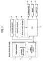
- Fig. 1 is a block diagram showing a schematic configuration of a device for controlling a distance between vehicles with a scanning-type radar to which a method according to an embodiment of the invention is applied.
- Fig. 1 illustrates the device for controlling a distance between vehicles as an example of a device to which the embodiment of the invention is applied, the method according to the embodiment of the invention can be applied to devices other than the device for controlling a distance between vehicles.
- a radar sensor section shown in Fig. 1 is directed to a mechanical scanning system, the embodiment of the invention can be applied to an electronic scanning system such as a phased array antenna system.
- the radar sensor section includes a radar antenna 1, a scanning mechanism 2, and a signal processing circuit 3.
- An ECU 7 for controlling a distance between vehicles receives signals from a steering sensor 4, a yaw rate sensor 5, a vehicle speed sensor 6, and the signal processing circuit 3 of the radar sensor section to control an alarm device 8, a brake 9, and a throttle 10.
- the ECU 7 also transmits a signal to the signal processing circuit 3 of the radar sensor section.
- Fig. 2 is a block diagram showing a configuration of the signal processing circuit 3 shown in Fig. 1.
- the signal processing circuit 3 includes a scanning angle control unit 11, a radar-signal processing unit 12 and a control object recognizing unit 13.
- the radar-signal processing unit 12 performs FFT-processing with respect to a reflecting signal from the radar antenna 1; detects a power spectrum; computes the distance to an object, relative speed of the object, and angle of the object; and sends the data computed to the control object recognizing unit 13.
- the control obj ect recognizing unit 13 gives a scanning angle to the scanning angle control unit 11 on the basis of: the distance to the object, the relative speed thereof and angle thereof received from the radar-signal processing unit 12; and vehicle information received from the ECU 7, which has been obtained from the steering sensor 4, the yaw rate sensor 5 and the vehicle speed sensor 6.
- the control object recognizing unit 13 also determines an object of control to transmit the determined object of control to the ECU 7.
- the scanning angle control unit 11 controls normal scanning and limited scanning describe later.
- the scanning angle control unit 11 stops the antenna at a predetermined angle. Also, the scanning angle control unit 11 controls the central position of the antenna and range of the scanning angle of the antenna in the limited scanning.
- the scanning mechanism 2 receives a control signal from the scanning control unit 11 to emit beams successively at a predetermined angle for scanning.
- Fig. 3 is a view showing a state of the "normal scanning" that is carried out when an object is not in an approaching state.
- reference symbol A denotes a user' s vehicle
- reference symbol B denotes a vehicle ahead, which is the target object.
- Fig. 4 is a view for explaining a close area in the embodiment of the invention.
- the vehicle ahead B comes close to the user's vehicle A to be within a predetermined distance from the user's vehicle A and enters a shaded close area E G .
- the vehicle ahead B is approaching at a relative speed not lower than a predetermined speed, it is determined that the object is in the approaching state.
- the vehicle ahead B functioning as the object is within a predetermined angle range when viewed from the user's vehicle A, it is determined that the object is in the approaching state.
- Figs. 5 and 6 are views showing how to operate the antenna as emergency processing when it is determined that the object is in the approaching state.
- Fig. 5 shows a state where the antenna is oriented to the front of the user's vehicle (hereinafter simply referred to as "the front") and is stopped as the emergency processing when it is determined that the object is in the approaching state.
- the front since the antenna is stopped while being oriented to the front, the object that is present in front of the user's vehicle and is at risk of collision can be intensively detected.
- Fig. 6 shows a state where when it is determined that an object is in the approaching state, the antenna scans in a limited scanning area E R around the angle at which the antenna is oriented to face the front as the emergency processing.
- the limited scanning area E R has a narrower angular range than that in the normal scanning.
- this scanning is referred to as "limited scanning".
- the scanning angle is decreased to shorten time taken for scanning once performed, thereby increasing the detection cycle of the object.
- the limited scanning is performed around the angle at which the antenna is oriented to face the front.
- an object that is present in front of the user's vehicle and is at risk of collision can be intensively detected.
- the above scanning angle and number of emitted beams in the normal scanning and the limited scanning are exemplary and may be set desirably.
- Figs. 7 and 8 are views showing another example on how to operate the antenna as emergency processing when it is determined that an object is in the approaching state.
- Fig. 7 shows a state where the antenna is oriented to the vehicle ahead B, which is a target object, and is stopped as the emergency processing when it is determined that the object is in the approaching state. In this way, since the antenna is stopped while being oriented to the object, the object that is present in the approaching state can be intensively detected.
- Fig. 8 shows a state where when it is determined that an object is in the approaching state, the antenna scans in a limited scanning area E R around the angle at which the antenna is oriented to face the vehicle ahead B as the emergency processing.
- the limited scanning area E R has a narrower angular range than that in the normal scanning. In this way, the limited scanning is performed around the angle at which the antenna is oriented to face the object. Thereby, an object that is in the approaching state can be intensively detected.
- Fig. 9 shows a state where when it is determined that an object is in the approaching state, the antenna is oriented to the vehicle ahead B, which is a target object, as the emergency processing; the antenna performs the "limited scanning" for scanning in a limited scanning area E R around such an angle; and the central angle of the limited scanning is changed every time a position of the vehicle ahead B is changed and thereby the angle of the antenna is changed.
- a vehicle ahead is used as an example of a target object
- an object should not be limited to a vehicle ahead. All objects (things fallen on a road, things fixed on a road shoulder, etc.), with which a user's vehicle must avoid to collide, may be a target object.
- Fig. 10 is a flowchart showing a first embodiment of this invention.
- the signal processing circuit 3 shown in Fig. 1 performs control shown in this flowchart. This applies to other flowcharts described later.
- the information such as the distance between the user's vehicle and the detected object, the relative speed therebetween, and the angle therebetween is output to the ECU 7 (S8). If 100 ms has not elapsed yet, the processing does not proceed to S7, but it is determined again in S6 whether or not 100 ms has elapsed.
- the processing is changed from the normal processing into the emergency processing (S9).
- the emergency processing includes stopping the antenna so as to be oriented in a predetermined direction, and executing the limited scanning with the antenna oriented in the predetermined direction.
- the object is recognized (S10).
- the distance between the user's vehicle and the object, the relative speed therebetween, and the angle therebetween at the moment are detected and stored as the object information (S11) so that the object information is updated (S12). It is assumed that in the emergency processing, scanning once takes about 20 ms.
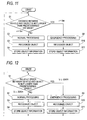
- Figs. 11 to 14 are flowcharts showing how to determine whether or not auser's vehicle is in a dangerous area in the first embodiment of the invention. These flowcharts specifically show how determination is made in the step (S1 of Fig. 10) where it is determined whether or not an object is in the approaching state. The remaining parts of the flowchart are the same as those in Fig. 10.
- a distance between the user' s vehicle and the detected object is not larger than a predetermined distance. For example, in S1, if it is determined that the distance r between the user's vehicle and the object is r ⁇ 5m, risk of collision is high. Therefore, it is determined that the object is in the approaching state (Yes). Thus, the emergency processing is performed (S9). On the other hand, if r > 5m, it is determined that the risk of collision is not so high. Thus, the normal processing is performed (S2).
- Fig. 12 shows another example.
- the radar scanning when the radar scanning is started, it is determined whether or not an object is in the approaching state (S1). In this case, it is determined whether or not the relative speed between the user's vehicle and the detected object is not smaller than a predetermined speed. For example, in S1, if it is determined that the relative speed v between the user's vehicle and the object is v ⁇ -30 km/h, i.e. the object approaches to the user's vehicle at a speed not lower than 30 km/h, the risk of collision is high. Therefore, it is determined that the object is in the approaching state (Yes). Thus, the emergency processing is performed (S9). On the other hand, if v > -30 km/h, it is determined that the risk of collision is not so high. Thus, the normal processing is performed (S2).
- Fig. 13 shows still another example.
- S1 when the radar scanning is started, it is determined whether or not an object is in the approaching state (S1). In this case, it is determined whether or not a distance between the user's vehicle and the detected object is not larger than a predetermined distance and whether or not the relative speed between the user's vehicle and the detected object is not lower than a predetermined speed.
- S1 if it is determined that the distance r between the user's vehicle and the detected obj ect is r ⁇ 5m and the relative speed v between the user' s vehicle and the object is v ⁇ -30 km/h, risk of collision is high. Therefore, it is determined that the object is in the approaching state (Yes). Thus, the emergency processing is performed (S9). On the other hand, if r > 5m and/or v > -30 km/h, it is determined that the risk of collision is not so high. Thus, the normal processing is performed (S2).
- Fig. 14 shows a further example.
- the radar scanning when the radar scanning is started, it is determined whether or not an object is in the approaching state (S1). In this case, it is determined whether or not the distance between the user's vehicle and the detected object is not larger than a predetermined distance, whether or not the relative speed between the user's vehicle and the detected object is not lower than a predetermined speed, and whether or not the angle between the user's vehicle and the detected obj ect is not larger than a predetermined value. If the angle is large, there is a higher possibility that the object is a vehicle running on an adjacent traffic lane. Therefore, the angle is adopted as criteria of the determination. Also, even if the obj ect is the vehicle running on the same traffic lane; the distance is short; and the relative speed is high, the risk of collision is low so long as the angle is not smaller than a predetermined angle.
- Fig. 15 is a flowchart showing a second embodiment of the invention.
- the antenna is immediately stopped at a position where the antenna is oriented to the front of the user's vehicle as the emergency processing and then the detected object is recognized.
- the present angle of the antenna that performs the normal scanning is detected (S3).
- This angle can be obtained by detecting how many degrees the antenna has moved leftward or rightward from the front direction of the user's vehicle indicated by line a. For example, if the antenna is at a position moved rightward by ⁇ °, the angle is+ ⁇ °. If the antenna is at a position moved leftward by ⁇ °, the angle is - ⁇ °.
- an antenna-position correction angle is computed (S4).
- the correction angle is + ⁇ ° or -8° described above.
- the antenna is stopped at the front position on the basis of the correction angle computed (S5), and then the approaching state flag (S6) is turned ON.
- the object is recognized with while the antenna is stopped and oriented to the front (S7).
- the distance between the user's vehicle and the object, the relative speed between the user's vehicle and the object, and the angle between the user's vehicle and the object at the moment are detected and stored as the object information (S8) so that the object information is updated (S9).
- the information updated is output (S10).
- the approaching state flag is ON (Yes) in S2
- the emergency processing has been performed in the previous flow and the antenna has been stopped with orienting to the front. Therefore, in this state, the object recognition is performed (S7).
- the object information is stored (S8).
- the object information is updated (S9). Finally, the information updated is output (S10).
- the approaching state flag is turned OFF (S11).
- the normal scanning is executed (S12).
- the processing from the object recognition (S13) to the information outputting (S18) is the same as that from S3 to S8 in Fig. 10.
- whether or not the object is in the approaching state can be determined on the basis of the distance between the user' s vehicle and the object, the relative speed between the user's vehicle and the object, and the angle between the user' s vehicle and the object as explained with reference to Figs. 11 to 14.
- Fig. 17 is a flowchart showing a third embodiment according to the invention.
- the antenna in a case where it is determined that an object is in the approaching state, the antenna is moved to a predetermined position for executing the limited scanning as the emergency processing and the detected object is recognized.
- Fig. 17 when the radar scanning is started, it is determined whether or not the object is in the approaching state (S1). If it is determined that the object is in the approaching state (Yes), whether or not the approaching state flag is ON is determined (S2). If it is first determined that the obj ect is in the approaching state (No) in S2, the following emergency processing will be performed.
- the present angle of the antenna that performs the normal scanning is detected (S3). This angle is the angle explained above with reference to Fig. 16.
- the antenna-position correction angle is computed (S4). This correction angle is an angle employed to move the antenna from the present position to the front position. Then, the position of the antenna is corrected to the front position on the basis of the correction angle computed (S5). The approaching state flag is turned ON (S6).
- the limited scanning is executed in a state where the position of the antenna is corrected, i.e. is executed around the angle at which the antenna is oriented to the front.
- the object is recognized (S8).
- the distance between the user's vehicle and the object, the relative speed between the user's vehicle and the object, and the angle between the users vehicle and the object at the moment are detected and stored as the object information (S9) so that the object information is updated (S10).
- the processing from step S11 to step S13 is the same as that of step S13 to step S8 in the flowchart of Fig. 10.
- the limited scanning is executed (S7), and the processing of the object recognition and the others are executed subsequently.
- the approaching state flag is turned OFF (S14).
- the normal scanning is executed (S15).
- the processing from the object recognition (S16) to the information outputting (S13) is the same as that from S3 to S8 in Fig. 10.
- whether or not the object is in the approaching state can be determined on the basis of the distance between the user' s vehicle and the object, the relative speed therebetween and the angle therebetween as explained with reference to Figs. 11 to 14.
- Fig. 18 is a flowchart showing a fourth embodiment according to the invention.
- the antenna when it is determined that an object is in the approaching state, the antenna is immediately stopped at the angle at which the antenna is oriented to the detected object as the emergency processing, and then the object is recognized.
- the angle between the user' s vehicle and the object detected is determined (S3).
- the present angle of the antenna that performs the normal scanning is detected (S4). This angle is the angle explained above with reference to Fig. 16.
- the antenna-position correction angle is computed (S5).
- the correction angle is a difference between the present angle of the antenna and the angle at which the antenna is oriented to the object.
- the antenna is stopped at the angle at which the antenna is oriented to the object (S6).
- the approaching state flag is turned ON (S7).
- the obj ect is recognized in a state where the antenna is stopped at the angle where the antenna is oriented to the object (S8).
- the distance between the antenna and the object, the relative speed therebetween, and the angle therebetween at the moment are detected and stored as the obj ect information (S9 ) so that the object information is updated (S10).
- the information updated is output (S11).
- the approaching state flag is ON (Yes) in S2
- the emergency processing has been executed in the previous flow and the antenna has been stopped at the angle at which the antenna is oriented to the object. Therefore, in this state, the object recognition is executed (S8), the object information is stored (S9), the object information is updated (S10) and the information updated is output (S11).
- the approaching state flag is turned OFF (S12). In this state, the normal scanning is executed (S13).
- the processing from the object recognition (S14) to the information outputting (S19) is the same as that from S3 to S8 in Fig. 10.
- whether or not the object is in the approaching state can be determined on the basis of the distance between the user's vehicle and the object, the relative speed therebetween, and the angle therebetween as explained with reference to Figs. 11 to 14.
- Fig. 19 is a flowchart showing a fifth embodiment according to the invention.
- the limited scanning is immediately executed around the angle at which the antenna is oriented to the object as the emergency processing and then, the detected object is recognized.
- the angle between the user's vehicle and the object detected is determined (S3).
- the present angle of the antenna that performs the normal scanning is detected (S4). This angle is the angle explained above with reference to Fig. 16.
- the antenna-position correction angle is computed (S5).
- the correction angle is a difference between the present angle of the antenna and the angle at which the antenna is oriented to the object.
- the antenna is moved and corrected to the angle at which the antenna is oriented to the object (S6), and then the approaching state flag is turned ON (S7).
- step S12 the limited scanning is executed around the angle at which the antenna is oriented to the object (S8), and the obj ect recognition is executed (S9).
- the distance between the user's vehicle and the object, the relative speed therebetween, and the angle therebetween at the moment are detected and stored as the object information (S10) so that the object information is updated (S11).
- the processing from step S12 to step S14 is the same as that in step S13 to step S8 in Fig. 10.
- the approaching state flag is ON (Yes) in S2
- the emergency processing has been executed in the previous flow and the antenna has performed the limited scanning around the angle at which the antenna is oriented to the object (S8). Therefore, in this state, the object recognition is executed (S9).
- the approaching state flag is turned OFF (S15). In this state, the normal scanning is executed (S16). The processing from the object recognition (S17) to the information outputting (S14) is the same as that from S3 to S8 in Fig. 10.
- whether or not the object is in the approaching state can be determined on the basis of the distance between the user' s vehicle and the object, the relative speed therebetween, and the angle therebetween as explained with reference to Figs. 11 to 14.
- Fig. 20 is a flowchart showing a sixth embodiment according to the invention.
- the limited scanning is immediately executed around the angle at which the antenna is oriented to the object as the emergency processing.
- the angle of the antenna is changed to another angle at which the antenna is oriented to the object; the limited scanning is executed around this another angle; and then the obj ect is recognized.
- Fig. 20 when the radar scanning is started, it is determined whether or not the object is in the approaching state (S1). If it is determined that the object is in the approaching state (Yes), the angle between the user's vehicle and the detected object is determined (S2). Next, the present angle of the antenna is detected (S3). This angle is the angle explained above with reference to Fig. 16.
- the antenna-position correction angle is computed (S4).
- the correction angle is a difference between the present angle of the antenna and the angle at which the antenna is oriented to the object.
- the antenna is moved and corrected to the angle at which the antenna is oriented to the object (S5).
- step S10 to step S12 is the same as that in step S13 to step S8 in Fig. 10.
- step S2 if it is determined that the object is still in the approaching state, the processing proceeds to step S2 again. At this moment, if a position of the object changes so that the angle between the user's angle and the object is changed, the antenna is corrected to the object angular position after changed (S5) and the limited scanning is executed around the resultant angle as shown in Fig. 9 (S6).
- step S14 to step S19 is the same as the processing from S3 to S8 in Fig. 10.
- Fig. 21 is a flowchart showing a seventh embodiment according to the invention.
- the emergency processing is performed and a warning is issued.
- the flowchart of Fig. 21 is substantially the same as that of Fig. 19.
- the flowchart of Fig. 21 is different from that of Fig. 19 in that when the emergency processing is performed on the basis of the determination that the object is in the approaching state, the warning is issued in step S8-1 by light flashing or voice.
- the warning is issued when the emergency processing is performed. Also, in the other embodiments, the warning may be likewise issued.
Landscapes
- Engineering & Computer Science (AREA)
- Radar, Positioning & Navigation (AREA)
- Remote Sensing (AREA)
- Computer Networks & Wireless Communication (AREA)
- Physics & Mathematics (AREA)
- General Physics & Mathematics (AREA)
- Radar Systems Or Details Thereof (AREA)
- Traffic Control Systems (AREA)
Abstract
A scanning method of an in-vehicle scanning-type radar
for emitting beams subsequently to execute scanning and for
detecting an object includes determining whether or not the
object is in an approaching state. When it is determined that
the object is not in the approaching state, executed is a first
scanning for scanning within a first angle range. When it is
determined that the object is in the approaching state, executed
is a second scanning for scanning within a second angle range
that is narrower than the first angle. A period during which
the radar scans the second angle range once in the second scanning
is shorter than that during which the radar scans the first angle
range once in the first scanning.
Description
- The present invention relates to a method for radar scanning, which switch between normal processing and emergency processing performed when it is determined that an object is in an approaching state.
- Radar for scanning a forward area to recognize an object has been applied to a tracking control device or collision preventing device.
- A method for detecting an obstacle for a vehicle has been proposed in a device provided with such a radar. In this method, it is determined whether or not an obstacle is dangerous andwhen there is a risk of collision, warning is issued (JP-A-2001-126196).
- A technique has been also proposed for setting a searching area and a scanning pattern according to a searching result in order for an object detection device to obtain appropriate information at all times (JP-A-2002-162469).
- A technique has been also proposed for increasing a scanning speed to decrease a data updating period in a warning mode and for decreasing the scanning speed to increase the data updating period in a following mode (JP-A-Hei.11-38133).
- Further, a radar device has been proposed for detecting the distance to a target by the beam scanning at a first step and for detecting the relative speed of the target by the beam scanning at a second step (JP-A-2000-9831).
- Further, in order to prevent a scanning motor and a driving circuit from being excessively heated in a preceding vehicle start detecting mode, a device has been also proposed for carrying out distance measurement through scanning by measuring means at least once and for fixing a distance measuring direction when the preceding vehicle start detecting mode is set on the basis of the measurement result (JP-A-2000-46947).
- Furthermore, an obstacle detecting device has been also proposed, which searches a preceding vehicle by laser scanning if there is not the preceding vehicle and causes the laser to follow the preceding vehicle when the preceding vehicle is detected so that the preceding vehicle is not lost during running a curve road (JP-A-Hei.11-160436).
- The radar generally performs scanning at a constant period and angle to recognize an obj ect. Therefore, even in a state where the object such as a vehicle ahead approaches to a user's vehicle, the scanning is executed at the constant period and angle. On the other hand, if the moving speed of the object is high, the processing of recognizing the obj ect must be adjusted to the movement of the object.
- In order to solve the above problem, the invention provides a method and a radar that switches the scanning method from a normal processing to an emergency processing when the object becomes in the approaching state and executes processing corresponding to the approaching state. Thereby, the object can be recognized quickly.
- According to one embodiment of the invention, a scanning method of an in-vehicle scanning-type radar for emitting beams subsequently to execute scanning and for detecting an object includes determining whether or not the object is in an approaching state. When it is determined that the object is not in the approaching state, executed is a first scanning for scanning within a first angle range. When it is determined that the object is in the approaching state, executed is a second scanning for scanning within a second angle range that is narrower than the first angle. A period during which the radar scans the second angle range once in the second scanning is shorter than that during which the radar scans the first angle range once in the first scanning.
- The radar may execute the second scanning with a front of a vehicle being in a center of the scanning. Alternatively, the radar may execute the second scanning with the detected obj ect being in a center of the scanning.
- Further alternatively, the radar may execute the second scanning with the detected obj ect being in a center of the scanning while the radar changes the center of the scanning in accordance with change of a position of the object.
- According to one embodiment of the invention, a scanning method of an in-vehicle scanning-type radar for emitting beams within a predetermined angle range subsequently to execute scanning and detecting an obj ect, includes determining whether or not the object is in an approaching state. When it is determined that the object is not in the approaching state, the radar scans within the predetermined angle range. When it is determined that the object is in the approaching state, the radar scans at a predetermined angle.
- The predetermined angle may correspond to a front of a vehicle. Alternatively, the predetermined angle may correspond to an angle at which the object is detected.
- When a distance between a vehicle and the object is not larger than a determined distance, it may be determined that the object is in the approaching state.
- Alternatively, when the object approaches to a vehicle at a relative speed not lower than a predetermined speed, it may be determined that the object is in the approaching state.
- Further alternatively, when a distance between a vehicle and the object is not larger than a predetermined distance and the object approaches to the vehicle at a relative speed not lower than a predetermined speed, it may be determined that the object is in the approaching state.
- Still further alternatively, when (a) a distance between a vehicle and the object is not larger than a predetermined distance; (b) the object approaches to the vehicle at a relative speed not lower than a predetermined speed; and (c) an angle between the radar and the object is not larger than a predetermined angle, it may be determined that the object is in the approaching state.
- When it is determined that the object is in the approaching state, warning may be issued.
- Object information including at least one of a distance between a vehicle and the object, a relative speed therebetween, and an angle therebetween may be stored.
- According to one embodiment of the invention, a radar emits beams subsequently to execute scanning and detects an object. The radar includes an antenna, a signal processing circuit, and a scanning mechanism. The antenna emits the beams and receives reflected beams. The signal processing circuit inputs transmission signals to the antenna to causes the antenna to emit the beams, receives reflected signals from the antenna in response to the reflected beams, determines whether or not the object is in an approaching state, and inputs control signals to the scanning mechanism. The scanning mechanism controls a direction of the antenna and an angle range of the scanning in accordance with the control signals input from the signal processing circuit. When the signal processing circuit determines that the object is not in the approaching state, the scanning mechanism controls the direction of the antenna to execute a first scanning for scanning within a first angle range. When the signal processing circuit determines that the object is in the approaching state, the scanning mechanism controls the direction of the antenna to execute a second scanning for scanning within a second angle range that is narrower than the first angle. A period during which the radar scans the second angle range once in the second scanning is shorter than that during which the radar scans the first angle range once in the first scanning.
- With the above described method and the radar, when the object becomes in the approaching state, the scanning method is switched from the normal processing to the emergency processing to execute processing corresponding to the approaching state. Thereby, the object being in the approaching state can be recognized and monitored quickly and intensively. As a result, collision between the user' s vehicle and the object can be avoided quickly and surely.
-
- Fig. 1 is a block diagram showing a schematic configuration of a device for controlling a distance between vehicles using a scanning-type radar according to one embodiment of the invention.
- Fig. 2 is a block diagram showing the configuration
of a
signal processing circuit 3 of Fig. 1. - Fig. 3 is a view showing a state of a normal scanning that is executed when an object is not in an approaching state.
- Fig. 4 is a view for explaining a close area in embodiments of the invention.
- Fig. 5 is a view showing a state where an antenna is stopped so as to be oriented to the front as emergency processing when it is determined that an object is in the approaching state.
- Fig. 6 is a view showing a state where when it is determined that an object is in the approaching state, an antenna is oriented to the front as the emergency processing and then the antenna executes a limited scanning around such an angle.
- Fig. 7 is a view showing a state where an antenna is stopped so as to be oriented to a vehicle ahead, which is a target object, as the emergency processing when it is determined that the obj ect is in the approaching state.
- Fig. 8 is a view showing a state where when it is determined that an object is in the approaching state, an antenna is oriented to a vehicle ahead, which is a target object, as the emergency processing and then the antenna executes the limited scanning around such an angle.
- Fig. 9 is a view showing a state where when it is determined that an object is in the approaching state, an antenna is oriented to a vehicle ahead, which is a target object, as the emergency processing; the antenna executes the limited scanning around such an angle; and whenever a position of the vehicle ahead changes so that the angle of the vehicle ahead is changed, the antenna executes the limited scanning around the resultant angle.
- Fig. 10 is a flowchart showing a first embodiment of the invention.
- Fig. 11 is a flowchart showing how to determine whether or not an object is in the approaching state.
- Fig. 12 is a flowchart showing how to determine whether or not an object is in the approaching state.
- Fig. 13 is a flowchart showing how to determine whether or not an object is in the approaching state.
- Fig. 14 is a flowchart showing how to determine whether or not an object is in the approaching state.
- Fig. 15 is a flowchart showing a second embodiment of the invention.
- Fig. 16 is a view for explaining a scanning angle.
- Fig. 17 is a flowchart showing a third embodiment of the invention.
- Fig. 18 is a flowchart showing a fourth embodiment of the invention.
- Fig. 19 is a flowchart showing a fifth embodiment of the invention.
- Fig. 20 is a flowchart showing a sixth embodiment of the invention.
- Fig. 21 is a flowchart showing a seventh embodiment of the invention.
-
- Fig. 1 is a block diagram showing a schematic configuration of a device for controlling a distance between vehicles with a scanning-type radar to which a method according to an embodiment of the invention is applied. Although Fig. 1 illustrates the device for controlling a distance between vehicles as an example of a device to which the embodiment of the invention is applied, the method according to the embodiment of the invention can be applied to devices other than the device for controlling a distance between vehicles. Although a radar sensor section shown in Fig. 1 is directed to a mechanical scanning system, the embodiment of the invention can be applied to an electronic scanning system such as a phased array antenna system.
- In Fig. 1, the radar sensor section includes a
radar antenna 1, ascanning mechanism 2, and asignal processing circuit 3. AnECU 7 for controlling a distance between vehicles receives signals from asteering sensor 4, ayaw rate sensor 5, avehicle speed sensor 6, and thesignal processing circuit 3 of the radar sensor section to control analarm device 8, abrake 9, and athrottle 10. TheECU 7 also transmits a signal to thesignal processing circuit 3 of the radar sensor section. - Fig. 2 is a block diagram showing a configuration of the
signal processing circuit 3 shown in Fig. 1. Thesignal processing circuit 3 includes a scanningangle control unit 11, a radar-signal processing unit 12 and a controlobject recognizing unit 13. The radar-signal processing unit 12 performs FFT-processing with respect to a reflecting signal from theradar antenna 1; detects a power spectrum; computes the distance to an object, relative speed of the object, and angle of the object; and sends the data computed to the controlobject recognizing unit 13. The control object recognizing unit 13 gives a scanning angle to the scanningangle control unit 11 on the basis of: the distance to the object, the relative speed thereof and angle thereof received from the radar-signal processing unit 12; and vehicle information received from theECU 7, which has been obtained from thesteering sensor 4, theyaw rate sensor 5 and thevehicle speed sensor 6. The controlobject recognizing unit 13 also determines an object of control to transmit the determined object of control to theECU 7. The scanningangle control unit 11 controls normal scanning and limited scanning describe later. The scanningangle control unit 11 stops the antenna at a predetermined angle. Also, the scanningangle control unit 11 controls the central position of the antenna and range of the scanning angle of the antenna in the limited scanning. Thescanning mechanism 2 receives a control signal from thescanning control unit 11 to emit beams successively at a predetermined angle for scanning. - Fig. 3 is a view showing a state of the "normal scanning" that is carried out when an object is not in an approaching state. In Fig. 3, reference symbol A denotes a user' s vehicle, and reference symbol B denotes a vehicle ahead, which is the target object. Further, in Fig. 3, Es denotes a normal scanning area. For example, in a range of = 16°, 16 (sixteen) beams are emitted ahead when the scanning is once performed.
- Fig. 4 is a view for explaining a close area in the embodiment of the invention. Where the vehicle ahead B comes close to the user's vehicle A to be within a predetermined distance from the user's vehicle A and enters a shaded close area EG, it is determined that the obj ect is in the approaching state. Also, when the vehicle ahead B is approaching at a relative speed not lower than a predetermined speed, it is determined that the object is in the approaching state. In addition, also when the vehicle ahead B functioning as the object is within a predetermined angle range when viewed from the user's vehicle A, it is determined that the object is in the approaching state.
- Figs. 5 and 6 are views showing how to operate the antenna as emergency processing when it is determined that the object is in the approaching state.
- Fig. 5 shows a state where the antenna is oriented to the front of the user's vehicle (hereinafter simply referred to as "the front") and is stopped as the emergency processing when it is determined that the object is in the approaching state. In this way, since the antenna is stopped while being oriented to the front, the object that is present in front of the user's vehicle and is at risk of collision can be intensively detected.
- Fig. 6 shows a state where when it is determined that an object is in the approaching state, the antenna scans in a limited scanning area ER around the angle at which the antenna is oriented to face the front as the emergency processing. The limited scanning area ER has a narrower angular range than that in the normal scanning. Hereinafter, this scanning is referred to as "limited scanning". In the case of the normal scanning described above, 16 beams are emitted forward within the range o f = 16° while the scanning is once performed. On the other hand, in the case of the limited scanning, 3 (three) beams are emitted forward within the range of = 3° while the scanning is once performed. Further, the scanning angle is decreased to shorten time taken for scanning once performed, thereby increasing the detection cycle of the object.
- In this way, the limited scanning is performed around the angle at which the antenna is oriented to face the front. Thereby, an object that is present in front of the user's vehicle and is at risk of collision can be intensively detected.
- Incidentally, it is needless to say that the above scanning angle and number of emitted beams in the normal scanning and the limited scanning are exemplary and may be set desirably.
- Figs. 7 and 8 are views showing another example on how to operate the antenna as emergency processing when it is determined that an object is in the approaching state.
- Fig. 7 shows a state where the antenna is oriented to the vehicle ahead B, which is a target object, and is stopped as the emergency processing when it is determined that the object is in the approaching state. In this way, since the antenna is stopped while being oriented to the object, the object that is present in the approaching state can be intensively detected.
- Fig. 8 shows a state where when it is determined that an object is in the approaching state, the antenna scans in a limited scanning area ER around the angle at which the antenna is oriented to face the vehicle ahead B as the emergency processing. The limited scanning area ER has a narrower angular range than that in the normal scanning. In this way, the limited scanning is performed around the angle at which the antenna is oriented to face the object. Thereby, an object that is in the approaching state can be intensively detected.
- Fig. 9 shows a state where when it is determined that an object is in the approaching state, the antenna is oriented to the vehicle ahead B, which is a target object, as the emergency processing; the antenna performs the "limited scanning" for scanning in a limited scanning area ER around such an angle; and the central angle of the limited scanning is changed every time a position of the vehicle ahead B is changed and thereby the angle of the antenna is changed.
- As shown in Fig. 9, when the vehicle ahead is located at a position B1, the "limited scanning" is performed in a narrower angle range ER1 than that in the normal scanning. When the vehicle ahead moves from the position B1 to a position B2, the limited scanning is performed in a narrower angle range ER2 than that in the normal scanning.
- In this way, even when the angle of the antenna changes as a result that an object moves, an object being in the approaching state can be intensively detected by changing the angle of the antenna as the object moves and performing the limited scanning around the angle at which the antenna is oriented to face the object.
- Incidentally, in the above explanation, although a vehicle ahead is used as an example of a target object, an object should not be limited to a vehicle ahead. All objects (things fallen on a road, things fixed on a road shoulder, etc.), with which a user's vehicle must avoid to collide, may be a target object.
- Fig. 10 is a flowchart showing a first embodiment of this invention. The
signal processing circuit 3 shown in Fig. 1 performs control shown in this flowchart. This applies to other flowcharts described later. - When radar scanning is started, it is determined whether or not an object is in the approaching state (S1). If it is determined that the object is not in the approaching state (NO), the normal processing is performed (S2). In the normal processing, the normal scanning is performed (S2) and the object is recognized (S3). A distance between the user' s vehicle and the object, the relative speed therebetween, and the angle therebetween at the moment are detected and stored as object information (S4) so that the object information is updated (S5). It is assumed that in the normal scanning, scanning once takes about 100 ms. It is determined whether or not 100 ms has elapsed (S6). If elapsed (Yes), a timer is reset (T = 0) (S7). The information such as the distance between the user's vehicle and the detected object, the relative speed therebetween, and the angle therebetween is output to the ECU 7 (S8). If 100 ms has not elapsed yet, the processing does not proceed to S7, but it is determined again in S6 whether or not 100 ms has elapsed.
- On the other hand, when it is determined whether or not the object is in the approaching state (S1) and then it is determined that the obj ect is in the approaching state (Yes) , the processing is changed from the normal processing into the emergency processing (S9). The emergency processing includes stopping the antenna so as to be oriented in a predetermined direction, and executing the limited scanning with the antenna oriented in the predetermined direction. Under the emergency processing, the object is recognized (S10). The distance between the user's vehicle and the object, the relative speed therebetween, and the angle therebetween at the moment are detected and stored as the object information (S11) so that the object information is updated (S12). It is assumed that in the emergency processing, scanning once takes about 20 ms. It is determined whether or not 20 ms has elapsed (S13). If elapsed (Yes), the timer is reset (T = 0) (S7). Then, the information such as the distance to the object, the relative speed thereof, and the angle thereof is output to the ECU 7 (S8). If 20 ms has not elapsed yet, the processing does not proceed to S7, but it is determined again in S13 whether or not 20 ms has elapsed.
- Figs. 11 to 14 are flowcharts showing how to determine whether or not auser's vehicle is in a dangerous area in the first embodiment of the invention. These flowcharts specifically show how determination is made in the step (S1 of Fig. 10) where it is determined whether or not an object is in the approaching state. The remaining parts of the flowchart are the same as those in Fig. 10.
- In Fig. 11, when the radar scanning is started, it is determined whether or not an obj ect is in the approaching state (S1). In this case, it is determined whether or not a distance between the user' s vehicle and the detected object is not larger than a predetermined distance. For example, in S1, if it is determined that the distance r between the user's vehicle and the object is r ≤ 5m, risk of collision is high. Therefore, it is determined that the object is in the approaching state (Yes). Thus, the emergency processing is performed (S9). On the other hand, if r > 5m, it is determined that the risk of collision is not so high. Thus, the normal processing is performed (S2).
- Fig. 12 shows another example. In Fig. 12, when the radar scanning is started, it is determined whether or not an object is in the approaching state (S1). In this case, it is determined whether or not the relative speed between the user's vehicle and the detected object is not smaller than a predetermined speed. For example, in S1, if it is determined that the relative speed v between the user's vehicle and the object is v ≤ -30 km/h, i.e. the object approaches to the user's vehicle at a speed not lower than 30 km/h, the risk of collision is high. Therefore, it is determined that the object is in the approaching state (Yes). Thus, the emergency processing is performed (S9). On the other hand, if v > -30 km/h, it is determined that the risk of collision is not so high. Thus, the normal processing is performed (S2).
- Fig. 13 shows still another example. In Fig. 13, when the radar scanning is started, it is determined whether or not an object is in the approaching state (S1). In this case, it is determined whether or not a distance between the user's vehicle and the detected object is not larger than a predetermined distance and whether or not the relative speed between the user's vehicle and the detected object is not lower than a predetermined speed. For example, in S1, if it is determined that the distance r between the user's vehicle and the detected obj ect is r ≤ 5m and the relative speed v between the user' s vehicle and the object is v ≤ -30 km/h, risk of collision is high. Therefore, it is determined that the object is in the approaching state (Yes). Thus, the emergency processing is performed (S9). On the other hand, if r > 5m and/or v > -30 km/h, it is determined that the risk of collision is not so high. Thus, the normal processing is performed (S2).
- Fig. 14 shows a further example. In Fig. 14, when the radar scanning is started, it is determined whether or not an object is in the approaching state (S1). In this case, it is determined whether or not the distance between the user's vehicle and the detected object is not larger than a predetermined distance, whether or not the relative speed between the user's vehicle and the detected object is not lower than a predetermined speed, and whether or not the angle between the user's vehicle and the detected obj ect is not larger than a predetermined value. If the angle is large, there is a higher possibility that the object is a vehicle running on an adjacent traffic lane. Therefore, the angle is adopted as criteria of the determination. Also, even if the obj ect is the vehicle running on the same traffic lane; the distance is short; and the relative speed is high, the risk of collision is low so long as the angle is not smaller than a predetermined angle.
- In Fig. 14, for example, in S1, if it is determined that the distance r between the user's vehicle and the detected object is r ≤ 5m; the relative speed v between the user's vehicle and the object is v ≤ -30 km/h; and the angle between the user's vehicle and the object is ≤ 3°, risk of collision is high. Therefore, it is determined that the object is in the approaching state (Yes). Thus, the emergency processing is performed (S9). On the other hand, if any one among r > 5m, v > -30 km/h, and > 3° is satisfied, it is determined that the risk of collision is not so high. Thus, the normal processing is performed (S2).
- Fig. 15 is a flowchart showing a second embodiment of the invention. In the second embodiment, if it is determined that the object is in the approaching state, the antenna is immediately stopped at a position where the antenna is oriented to the front of the user's vehicle as the emergency processing and then the detected object is recognized.
- In Fig. 15, when the radar scanning is started, it is determined whether or not an obj ect is in the approaching state (S1). If it is determined that the object is in the approaching state (Yes) , whether or not an approaching state flag is ON is determined (S2). If it is first determined that the object is in the approaching state (No) in S2, the following emergency processing will be performed.
- First, the present angle of the antenna that performs the normal scanning is detected (S3). This angle can be obtained by detecting how many degrees the antenna has moved leftward or rightward from the front direction of the user's vehicle indicated by line a. For example, if the antenna is at a position moved rightward by °, the angle is+°. If the antenna is at a position moved leftward by °, the angle is -°.
- Next, an antenna-position correction angle is computed (S4). In this case, since the antenna is stopped at the position oriented to the front, the correction angle is +° or -8° described above. The antenna is stopped at the front position on the basis of the correction angle computed (S5), and then the approaching state flag (S6) is turned ON.
- Next, the object is recognized with while the antenna is stopped and oriented to the front (S7). The distance between the user's vehicle and the object, the relative speed between the user's vehicle and the object, and the angle between the user's vehicle and the object at the moment are detected and stored as the object information (S8) so that the object information is updated (S9). The information updated is output (S10).
- On the other hand, if the approaching state flag is ON (Yes) in S2, the emergency processing has been performed in the previous flow and the antenna has been stopped with orienting to the front. Therefore, in this state, the object recognition is performed (S7). The object information is stored (S8). The object information is updated (S9). Finally, the information updated is output (S10).
- Incidentally, if it is determined in S1 that the object is not in the approaching state (No), the approaching state flag is turned OFF (S11). The normal scanning is executed (S12). The processing from the object recognition (S13) to the information outputting (S18) is the same as that from S3 to S8 in Fig. 10.
- In the second embodiment shown in Fig. 15, whether or not the object is in the approaching state can be determined on the basis of the distance between the user' s vehicle and the object, the relative speed between the user's vehicle and the object, and the angle between the user' s vehicle and the object as explained with reference to Figs. 11 to 14.
- Fig. 17 is a flowchart showing a third embodiment according to the invention. In the third embodiment, in a case where it is determined that an object is in the approaching state, the antenna is moved to a predetermined position for executing the limited scanning as the emergency processing and the detected object is recognized.
- In Fig. 17, when the radar scanning is started, it is determined whether or not the object is in the approaching state (S1). If it is determined that the object is in the approaching state (Yes), whether or not the approaching state flag is ON is determined (S2). If it is first determined that the obj ect is in the approaching state (No) in S2, the following emergency processing will be performed.
- First, the present angle of the antenna that performs the normal scanning is detected (S3). This angle is the angle explained above with reference to Fig. 16. Next, the antenna-position correction angle is computed (S4). This correction angle is an angle employed to move the antenna from the present position to the front position. Then, the position of the antenna is corrected to the front position on the basis of the correction angle computed (S5). The approaching state flag is turned ON (S6).
- Next, the limited scanning is executed in a state where the position of the antenna is corrected, i.e. is executed around the angle at which the antenna is oriented to the front. The object is recognized (S8). The distance between the user's vehicle and the object, the relative speed between the user's vehicle and the object, and the angle between the users vehicle and the object at the moment are detected and stored as the object information (S9) so that the object information is updated (S10). The processing from step S11 to step S13 is the same as that of step S13 to step S8 in the flowchart of Fig. 10.
- On the other hand, if the approaching state flag is ON (Yes) in S2, the limited scanning has been executed in the previous flow and the antenna has been at the position for the limited scanning. Therefore, in this state, the limited scanning is executed (S7), and the processing of the object recognition and the others are executed subsequently.
- Incidentally, if it is determined in S1 that the object is not in the approaching state (No), the approaching state flag is turned OFF (S14). The normal scanning is executed (S15). The processing from the object recognition (S16) to the information outputting (S13) is the same as that from S3 to S8 in Fig. 10.
- In the third embodiment shown in Fig. 17, whether or not the object is in the approaching state can be determined on the basis of the distance between the user' s vehicle and the object, the relative speed therebetween and the angle therebetween as explained with reference to Figs. 11 to 14.
- Fig. 18 is a flowchart showing a fourth embodiment according to the invention. In the fourth embodiment, when it is determined that an object is in the approaching state, the antenna is immediately stopped at the angle at which the antenna is oriented to the detected object as the emergency processing, and then the object is recognized.
- In Fig. 18, when the radar scanning is started, it is determined whether or not the object is in the approaching state (S1). If it is determined that the object is in the approaching state (Yes) , whether or not the approaching state flag is ON is determined (S2). If it is first determined that the object is in the approaching state (No) in S2, the following emergency processing will be performed.
- First, the angle between the user' s vehicle and the object detected is determined (S3). Next, the present angle of the antenna that performs the normal scanning is detected (S4). This angle is the angle explained above with reference to Fig. 16.
- Next, the antenna-position correction angle is computed (S5). In this case, since the antenna is stopped at the angle at which the antenna is oriented to the object, the correction angle is a difference between the present angle of the antenna and the angle at which the antenna is oriented to the object. On the basis of the correction angle computed, the antenna is stopped at the angle at which the antenna is oriented to the object (S6). Then, the approaching state flag is turned ON (S7).
- The obj ect is recognized in a state where the antenna is stopped at the angle where the antenna is oriented to the object (S8). The distance between the antenna and the object, the relative speed therebetween, and the angle therebetween at the moment are detected and stored as the obj ect information (S9 ) so that the object information is updated (S10). The information updated is output (S11).
- On the other hand, if the approaching state flag is ON (Yes) in S2, the emergency processing has been executed in the previous flow and the antenna has been stopped at the angle at which the antenna is oriented to the object. Therefore, in this state, the object recognition is executed (S8), the object information is stored (S9), the object information is updated (S10) and the information updated is output (S11).
- Incidentally, if it is determined in S1 that the object is not in the approaching state (No), the approaching state flag is turned OFF (S12). In this state, the normal scanning is executed (S13). The processing from the object recognition (S14) to the information outputting (S19) is the same as that from S3 to S8 in Fig. 10.
- In the fourth embodiment shown in Fig. 18, whether or not the object is in the approaching state can be determined on the basis of the distance between the user's vehicle and the object, the relative speed therebetween, and the angle therebetween as explained with reference to Figs. 11 to 14.
- Fig. 19 is a flowchart showing a fifth embodiment according to the invention. In the fifth embodiment, when it is determined that an object is in the approaching state, the limited scanning is immediately executed around the angle at which the antenna is oriented to the object as the emergency processing and then, the detected object is recognized.
- In Fig. 19, when the radar scanning is started, it is determined whether or not the object is in the approaching state (S1). If it is determined that the object is in the approaching state (Yes), whether or not the approaching state flag is ON is determined (S2). If it is first determined that the object is in the approaching state (No) in S2, the following emergency processing will be performed.
- First, the angle between the user's vehicle and the object detected is determined (S3). Next, the present angle of the antenna that performs the normal scanning is detected (S4). This angle is the angle explained above with reference to Fig. 16.
- Next, the antenna-position correction angle is computed (S5). In this case, since the limited scanning is executed around the angle at which the antenna is oriented to the object, the correction angle is a difference between the present angle of the antenna and the angle at which the antenna is oriented to the object. On the basis of the correction angle computed, the antenna is moved and corrected to the angle at which the antenna is oriented to the object (S6), and then the approaching state flag is turned ON (S7).
- Next, the limited scanning is executed around the angle at which the antenna is oriented to the object (S8), and the obj ect recognition is executed (S9). The distance between the user's vehicle and the object, the relative speed therebetween, and the angle therebetween at the moment are detected and stored as the object information (S10) so that the object information is updated (S11). The processing from step S12 to step S14 is the same as that in step S13 to step S8 in Fig. 10.
- On the other hand, if the approaching state flag is ON (Yes) in S2, the emergency processing has been executed in the previous flow and the antenna has performed the limited scanning around the angle at which the antenna is oriented to the object (S8). Therefore, in this state, the object recognition is executed (S9).
- Incidentally, if it is determined in S1 that the object is not in the approaching state (No), the approaching state flag is turned OFF (S15). In this state, the normal scanning is executed (S16). The processing from the object recognition (S17) to the information outputting (S14) is the same as that from S3 to S8 in Fig. 10.
- In the fifth embodiment shown in Fig. 19, whether or not the object is in the approaching state can be determined on the basis of the distance between the user' s vehicle and the object, the relative speed therebetween, and the angle therebetween as explained with reference to Figs. 11 to 14.
- Fig. 20 is a flowchart showing a sixth embodiment according to the invention. In the sixth embodiment, when it is determined that the object is in the approaching state, the limited scanning is immediately executed around the angle at which the antenna is oriented to the object as the emergency processing. In addition, whenever a position of the object changes so that an angle between the user's vehicle and the object is changed, the angle of the antenna is changed to another angle at which the antenna is oriented to the object; the limited scanning is executed around this another angle; and then the obj ect is recognized.
- In Fig. 20, when the radar scanning is started, it is determined whether or not the object is in the approaching state (S1). If it is determined that the object is in the approaching state (Yes), the angle between the user's vehicle and the detected object is determined (S2). Next, the present angle of the antenna is detected (S3). This angle is the angle explained above with reference to Fig. 16.
- Next, the antenna-position correction angle is computed (S4). In this case, since the limited scanning is executed around antenna at which the angle is oriented to the object, the correction angle is a difference between the present angle of the antenna and the angle at which the antenna is oriented to the object. On the basis of the correction angle computed, the antenna is moved and corrected to the angle at which the antenna is oriented to the object (S5).
- Next, the limited scanning is executed around the angle at which the antenna is oriented to the object (S6) and then, the object recognition is executed (S7). The distance between the user's vehicle and the object, the relative speed therebetween and the angle therebetween at the moment are detected and stored as the object information (S8) so that the object information is updated (S9). The processing from step S10 to step S12 is the same as that in step S13 to step S8 in Fig. 10.
- In the subsequent flow, if it is determined that the object is still in the approaching state, the processing proceeds to step S2 again. At this moment, if a position of the object changes so that the angle between the user's angle and the object is changed, the antenna is corrected to the object angular position after changed (S5) and the limited scanning is executed around the resultant angle as shown in Fig. 9 (S6).
- On the other hand, if it is determined in S1 that the object is not in the approaching state (No), the normal scanning is executed (S13). The processing from step S14 to step S19 is the same as the processing from S3 to S8 in Fig. 10.
- In the sixth embodiment shown in Fig. 20, whether or not the object is in the approaching state can be determined on the bas is of the distance between the user' s vehicle and the object, the relative speed therebetween and the angle therebetween as explained with reference to Figs. 11 to 14.
- Fig. 21 is a flowchart showing a seventh embodiment according to the invention. In the seventh embodiment, when it is determined that the object is in the approaching state, the emergency processing is performed and a warning is issued.
- The flowchart of Fig. 21 is substantially the same as that of Fig. 19. The flowchart of Fig. 21 is different from that of Fig. 19 in that when the emergency processing is performed on the basis of the determination that the object is in the approaching state, the warning is issued in step S8-1 by light flashing or voice.
- As described above, in the embodiment shown in Fig. 21, the warning is issued when the emergency processing is performed. Also, in the other embodiments, the warning may be likewise issued.
- Although the above embodiments have been explained in connection with the operation of the radar sensor section in the mechanical scanning system, it is needless to say that the same operation can be performed in the apparatus having the radar sensor section in the electronic scanning system as described above.
Claims (24)
- A scanning method of an in-vehicle scanning-type radar for emitting beams subsequently to execute scanning and for detecting an object, the method comprising:determining whether or not the object is in an approaching state;when it is determined that the object is not in the approaching state, executing a first scanning for scanning within a first angle range; andwhen it is determined that the object is in the approaching state, executing a second scanning for scanning within a second angle range that is narrower than the first angle, wherein:a period during which the radar scans the second angle range once in the second scanning is shorter than that during which the radar scans the first angle range once in the first scanning.
- The method according to claim 1, wherein the radar executes the second scanning with a front of a vehicle being in a center of the scanning.
- The method according to claim 1, wherein the radar executes the second scanning with the detected object being in a center of the scanning.
- The method according to claim 1, wherein the radar executes the second scanning with the detected object being in a center of the scanning while the radar changes the center of the scanning in accordance with change of a position of the obj ect.
- A scanning method of an in-vehicle scanning-type radar for emitting beams within a predetermined angle range subsequently to execute scanning and detecting an object, the method comprising:determining whether or not the obj ect is in an approaching state;when it is determined that the object is not in the approaching state, scanning within the predetermined angle range; andwhen it is determined that the object is in the approaching state, scanning at a predetermined angle.
- The method according to claim 5, wherein the predetermined angle corresponds to a front of a vehicle.
- The method according to claim 6, wherein the predetermined angle corresponds to an angle at which the object is detected.
- The method according to any one of claims 1 to 7, wherein when a distance between a vehicle and the object is not larger than a determined distance, it is determined that the object is in the approaching state.
- The method according to any one of claims 1 to 7, wherein when the object approaches to a vehicle at a relative speed not lower than a predetermined speed, it is determined that the object is in the approaching state.
- The method according to any one of claims 1 to 7, wherein when a distance between a vehicle and the object is not larger than a predetermined distance and the object approaches to the vehicle at a relative speed not lower than a predetermined speed, it is determined that the object is in the approaching state.
- The method according to claim any one of claims 1 to 7, wherein when (a) a distance between a vehicle and the obj ect is not larger than a predetermined distance; (b) the object approaches to the vehicle at a relative speed not lower than a predetermined speed; and (c) an angle between the radar and the object is not larger than a predetermined angle, it is determined that the object is in the approaching state.
- The method according to any one of claims 1 to 11, further comprising:when it is determined that the obj ect is in the approaching state, issuing warning.
- The method according to any one of claims 1 to 12, further comprising:storing object information including at least one of a distance between a vehicle and the object, a relative speed therebetween, and an angle therebetween.
- A radar for emitting beams subsequently to execute scanning and detecting an object, the radar comprising:an antenna that emits the beams and receives reflected beams;a signal processing circuit that inputs transmission signals to the antenna to causes the antenna to emit the beams, receives reflected signals from the antenna in response to the reflected beams, determines whether or not the object is in an approaching state, and inputs control signals to a scanning mechanism; andthe scanning mechanism that controls a direction of the antenna and an angle range of the scanning in accordance with the control signals input from the signal processing circuit, wherein:when the signal processing circuit determines that the object is not in the approaching state, the scanning mechanism controls the direction of the antenna to execute a first scanning for scanning within a first angle range;when the signal processing circuit determines that the object is in the approaching state, the scanning mechanism controls the direction of the antenna to execute a second scanning for scanning within a second angle range that is narrower than the first angle; anda period during which the radar scans the second angle range once in the second scanning is shorter than that during which the radar scans the first angle range once in the first scanning.
- The radar according to claim 14, wherein in the second scanning, the scanning mechanism changes the direction of the antenna with a front of a vehicle being in a center of the scanning.
- The radar according to claim 14, wherein in the second scanning, the scanning mechanism changes the direction of the antenna with the detected object being in a center of the scanning.
- The radar according to claim 14, wherein in the second scanning, the scanning mechanism changes the direction of the antenna with the detected obj ect being in a center of the scanning while changing the center of the scanning in accordance with change of a position of the object.
- The radar according to any one of claims 14 to 17, wherein the second angle range consists of a predetermined angle.
- The radar according to any one of claims 14 to 18, wherein:the signal processing circuit calculates a distance between a vehicle and the object on the basis of the transmission signals and the reflected signal; andwhen the calculated distance therebetween is not larger than a determined distance, the signal processing circuit determines that the object is in the approaching state.
- The radar according to any one of claims 14 to 18, wherein:the signal processing circuit calculates a relative speed between a vehicle and the object on the basis of the transmission signals and the reflected signal; andwhen the object approaches to a vehicle at the relative speed not lower than a predetermined speed, the signal processing circuit determines that the object is in the approaching state.
- The radar according to any one of claims 14 to 18, wherein:the signal processing circuit calculates:a distance between a vehicle and the object; anda relative speed therebetween; on the basis of the transmission signals and the reflected signal; andwhen the calculated distance therebetween is not larger than a predetermined distance and the object approaches to the vehicle at the relative speed not lower than a predetermined speed, the signal processing circuit determines that the object is in the approaching state.
- The method according to claim any one of claims 14 to 18, wherein:the signal processing circuit calculates:a distance between a vehicle and the object;a relative speed therebetween; andan angle therebetween; on the basis of the transmission signals and the reflected signal; andwhen (a) the distance therebetween is not larger than a predetermined distance; (b) the obj ect approaches to the vehicle at the relative speed not lower than a predetermined speed; and (c) the angle therebetween is not larger than a predetermined angle, the signal processing circuit determines that the object is in the approaching state
- The method according to any one of claims 14 to 22, further comprising:an alarm device that issues warning when the signal processing circuit determines that that the object is in the approaching state.
- The method according to any one of claims 14 to 23, wherein the signal processing circuit outputs obj ect information including at least one of a distance between a vehicle and the object, a relative speed therebetween, and an angle therebetween.
Applications Claiming Priority (2)
| Application Number | Priority Date | Filing Date | Title |
|---|---|---|---|
| JP2003364818 | 2003-10-24 | ||
| JP2003364818A JP2005127909A (en) | 2003-10-24 | 2003-10-24 | Scanning method of radar |
Publications (1)
| Publication Number | Publication Date |
|---|---|
| EP1530062A1 true EP1530062A1 (en) | 2005-05-11 |
Family
ID=34431221
Family Applications (1)
| Application Number | Title | Priority Date | Filing Date |
|---|---|---|---|
| EP04256505A Ceased EP1530062A1 (en) | 2003-10-24 | 2004-10-22 | Radar scanning method |
Country Status (5)
| Country | Link |
|---|---|
| US (1) | US7417585B2 (en) |
| EP (1) | EP1530062A1 (en) |
| JP (1) | JP2005127909A (en) |
| KR (1) | KR100679542B1 (en) |
| CN (1) | CN1318856C (en) |
Families Citing this family (30)
| Publication number | Priority date | Publication date | Assignee | Title |
|---|---|---|---|---|
| JP2006162341A (en) * | 2004-12-03 | 2006-06-22 | Fujitsu Ten Ltd | Radar system of scanning type |
| DE102004062801A1 (en) * | 2004-12-20 | 2006-06-22 | Balluff Gmbh | High frequency position and path sensor for detecting approach of an object to a detection area in near field having main transmission and reception directions at a angle to each other |
| US7489265B2 (en) * | 2005-01-13 | 2009-02-10 | Autoliv Asp, Inc. | Vehicle sensor system and process |
| JP2007030603A (en) * | 2005-07-25 | 2007-02-08 | Mazda Motor Corp | Vehicle travel support device |
| US7724180B2 (en) * | 2007-05-04 | 2010-05-25 | Toyota Motor Corporation | Radar system with an active lens for adjustable field of view |
| JP5320792B2 (en) * | 2008-03-28 | 2013-10-23 | 富士通株式会社 | Arrival direction estimation apparatus, arrival direction estimation method, and arrival direction estimation program |
| JP2013156139A (en) * | 2012-01-30 | 2013-08-15 | Ihi Corp | Moving object detecting apparatus and moving object detecting method |
| JP2013156138A (en) * | 2012-01-30 | 2013-08-15 | Ihi Corp | Moving object detecting apparatus |
| JP5996878B2 (en) * | 2012-02-13 | 2016-09-21 | 株式会社デンソー | Radar equipment |
| US9116227B2 (en) * | 2012-02-22 | 2015-08-25 | Toyota Motor Engineering & Manufacturing North America, Inc. | Hybrid radar integrated into single package |
| CN103076609A (en) * | 2012-11-14 | 2013-05-01 | 武汉德澳科技有限公司 | Solid small-sized microwave electronic control scanning travelling crane radar device |
| JP6181924B2 (en) * | 2012-12-06 | 2017-08-16 | 富士通テン株式会社 | Radar apparatus and signal processing method |
| US9274222B1 (en) * | 2013-03-04 | 2016-03-01 | Toyota Motor Engineering & Manufacturing North America, Inc. | Dynamic allocation of radar beams in automotive environments with phased array radar |
| JP6175863B2 (en) | 2013-03-29 | 2017-08-09 | 富士通株式会社 | Radar apparatus and program |
| JP6164051B2 (en) * | 2013-11-04 | 2017-07-19 | 株式会社デンソー | Sensor system, control device, and sensor |
| JP6511890B2 (en) * | 2015-03-19 | 2019-05-15 | 株式会社Soken | Direction estimation system and direction estimation apparatus |
| KR20170011882A (en) * | 2015-07-24 | 2017-02-02 | 엘지전자 주식회사 | Radar for vehicle, and vehicle including the same |
| JP6563849B2 (en) * | 2016-05-06 | 2019-08-21 | 株式会社Soken | Estimator |
| JP6535302B2 (en) * | 2016-07-13 | 2019-06-26 | 株式会社Soken | Object detection device |
| CN106781242B (en) * | 2016-11-25 | 2019-03-12 | 北京小米移动软件有限公司 | The method for early warning and device of danger zone |
| CN111521988B (en) * | 2019-02-01 | 2023-11-14 | 比亚迪股份有限公司 | Radar angle measurement method, device, radar and vehicle based on beam forming |
| KR102818487B1 (en) | 2019-11-26 | 2025-06-11 | 삼성전자주식회사 | Radar apparatus and method of operating the same |
| JP7581837B2 (en) * | 2019-12-20 | 2024-11-13 | 株式会社デンソー | Radar Equipment |
| US11953586B2 (en) | 2020-11-17 | 2024-04-09 | Ford Global Technologies, Llc | Battery-powered vehicle sensors |
| CN112822667A (en) * | 2020-12-31 | 2021-05-18 | 安克创新科技股份有限公司 | Safe driving assistance method, device and system based on Bluetooth and storage medium |
| US11614513B2 (en) | 2021-03-12 | 2023-03-28 | Ford Global Technologies, Llc | Battery-powered vehicle sensors |
| US11912235B2 (en) | 2021-03-12 | 2024-02-27 | Ford Global Technologies, Llc | Vehicle object detection |
| US11951937B2 (en) | 2021-03-12 | 2024-04-09 | Ford Global Technologies, Llc | Vehicle power management |
| US11916420B2 (en) | 2021-03-12 | 2024-02-27 | Ford Global Technologies, Llc | Vehicle sensor operation |
| CN113131214A (en) * | 2021-03-29 | 2021-07-16 | 安徽博微长安电子有限公司 | Antenna dynamic sector scanning control method and control system |
Citations (3)
| Publication number | Priority date | Publication date | Assignee | Title |
|---|---|---|---|---|
| US6067038A (en) * | 1997-08-21 | 2000-05-23 | Mitsubishi Denki Kabushiki Kaisha | Vehicle-mounted radar apparatus |
| JP2001027670A (en) * | 1999-07-13 | 2001-01-30 | Mitsubishi Electric Corp | Detecting method and detecting device |
| US20020157887A1 (en) * | 2001-04-27 | 2002-10-31 | Ryoichi Sugawara | Optical object detection apparatus designed to monitor front and lateral zones of vehicle |
Family Cites Families (18)
| Publication number | Priority date | Publication date | Assignee | Title |
|---|---|---|---|---|
| US4573050A (en) * | 1983-02-17 | 1986-02-25 | The United States Of America As Represented By The Secretary Of The Navy | Dual scan rate radar |
| JP3217566B2 (en) * | 1993-12-28 | 2001-10-09 | 富士通株式会社 | Continuous wave radar |
| JP3119142B2 (en) * | 1995-12-04 | 2000-12-18 | トヨタ自動車株式会社 | In-vehicle radar device |
| JP3314623B2 (en) * | 1996-08-12 | 2002-08-12 | トヨタ自動車株式会社 | In-vehicle scanning radar |
| JPH1138133A (en) | 1997-07-15 | 1999-02-12 | Mitsubishi Electric Corp | Automotive radar equipment |
| JP3690079B2 (en) * | 1997-08-28 | 2005-08-31 | 日産自動車株式会社 | Inter-vehicle distance alarm device |
| JPH11160436A (en) | 1997-11-28 | 1999-06-18 | Unisia Jecs Corp | Obstacle detection device |
| JP3361741B2 (en) | 1998-03-31 | 2003-01-07 | 富士通テン株式会社 | Scanning radar signal processor |
| JP2000009831A (en) | 1998-06-26 | 2000-01-14 | Toyota Motor Corp | Radar equipment |
| JP2000046947A (en) | 1998-07-28 | 2000-02-18 | Nissan Motor Co Ltd | Front vehicle start notification device |
| JP2000075030A (en) * | 1998-08-27 | 2000-03-14 | Aisin Seiki Co Ltd | Scan type laser radar device |
| JP3174831B2 (en) | 1999-10-27 | 2001-06-11 | 建設省土木研究所長 | Obstacle collision prevention system |
| JP2001126194A (en) | 1999-10-29 | 2001-05-11 | Nippon Avionics Co Ltd | Vehicle obstacle detection method, vehicle obstacle detection device, and recording medium |
| DE10011263A1 (en) | 2000-03-08 | 2001-09-13 | Bosch Gmbh Robert | Object detection system for adaptive cruise control system of vehicle, includes radar sensor with large and small detection ranges |
| JP2002162469A (en) | 2000-11-28 | 2002-06-07 | Nhk Spring Co Ltd | Object detection device |
| JP2003090877A (en) | 2001-07-12 | 2003-03-28 | Murata Mfg Co Ltd | Radar device |
| JP4156307B2 (en) * | 2002-09-09 | 2008-09-24 | 株式会社デンソー | Radar device, program |
| KR100471268B1 (en) * | 2002-10-28 | 2005-03-10 | 현대자동차주식회사 | Method for detecting vehicle distance |
-
2003
- 2003-10-24 JP JP2003364818A patent/JP2005127909A/en active Pending
-
2004
- 2004-10-22 EP EP04256505A patent/EP1530062A1/en not_active Ceased
- 2004-10-22 KR KR1020040084726A patent/KR100679542B1/en not_active Expired - Fee Related
- 2004-10-25 CN CNB2004100859505A patent/CN1318856C/en not_active Expired - Fee Related
- 2004-10-25 US US10/971,165 patent/US7417585B2/en not_active Expired - Fee Related
Patent Citations (3)
| Publication number | Priority date | Publication date | Assignee | Title |
|---|---|---|---|---|
| US6067038A (en) * | 1997-08-21 | 2000-05-23 | Mitsubishi Denki Kabushiki Kaisha | Vehicle-mounted radar apparatus |
| JP2001027670A (en) * | 1999-07-13 | 2001-01-30 | Mitsubishi Electric Corp | Detecting method and detecting device |
| US20020157887A1 (en) * | 2001-04-27 | 2002-10-31 | Ryoichi Sugawara | Optical object detection apparatus designed to monitor front and lateral zones of vehicle |
Non-Patent Citations (1)
| Title |
|---|
| PATENT ABSTRACTS OF JAPAN vol. 2000, no. 16 8 May 2001 (2001-05-08) * |
Also Published As
| Publication number | Publication date |
|---|---|
| US7417585B2 (en) | 2008-08-26 |
| JP2005127909A (en) | 2005-05-19 |
| CN1609632A (en) | 2005-04-27 |
| KR100679542B1 (en) | 2007-02-07 |
| KR20050039638A (en) | 2005-04-29 |
| CN1318856C (en) | 2007-05-30 |
| US20050140541A1 (en) | 2005-06-30 |
Similar Documents
| Publication | Publication Date | Title |
|---|---|---|
| US7417585B2 (en) | Radar scanning method | |
| JP2900737B2 (en) | Inter-vehicle distance detection device | |
| JP3331882B2 (en) | Central axis deflection amount calculating device, central axis deflection amount correcting device, and inter-vehicle control device of vehicle obstacle detection device | |
| EP1065520B1 (en) | Vehicle control method and vehicle warning method | |
| EP2009464B1 (en) | Object detection device | |
| US6147637A (en) | Obstacle detecting system for automotive vehicle | |
| US5585798A (en) | Obstacle detection system for automotive vehicle | |
| EP1316935B1 (en) | Traffic environment recognition method and system for carrying out the same | |
| US6025797A (en) | Angular shift determining apparatus for determining angular shift of central axis of radar used in automotive obstacle detection system | |
| US6484087B2 (en) | Method of selecting a preceding vehicle, a preceding vehicle selecting apparatus, and a recording medium for selecting a preceding vehicle | |
| US9008940B2 (en) | Vehicle control device and vehicle control method | |
| US5767803A (en) | Radar apparatus for accurately detecting a path of a target vehicle which is in a lane of a vehicle | |
| US5828968A (en) | Method of controlling automatically driven motor vehicle | |
| JPH05196736A (en) | Vehicle radar device | |
| JP2906894B2 (en) | Inter-vehicle distance detection device | |
| JP7614563B2 (en) | Collision avoidance device, collision avoidance method, and collision avoidance program | |
| JP2000180537A (en) | Method for identifying target to be controlled of scan- type radar | |
| JP2003200753A (en) | Vehicle tracking device | |
| JP3514166B2 (en) | Preceding vehicle recognition device | |
| EP1417512B1 (en) | Near object detection system | |
| JP3946598B2 (en) | Vehicle following traveling device | |
| US11435474B2 (en) | Vehicle system for detection of oncoming vehicles | |
| JP4138441B2 (en) | Vehicle control device | |
| JPH06282798A (en) | Target searching device and alarm device and automatic tracking device using the same | |
| US12546897B2 (en) | Driver assistance system and operation method thereof |
Legal Events
| Date | Code | Title | Description |
|---|---|---|---|
| PUAI | Public reference made under article 153(3) epc to a published international application that has entered the european phase |
Free format text: ORIGINAL CODE: 0009012 |
|
| AK | Designated contracting states |
Kind code of ref document: A1 Designated state(s): AT BE BG CH CY CZ DE DK EE ES FI FR GB GR HU IE IT LI LU MC NL PL PT RO SE SI SK TR |
|
| AX | Request for extension of the european patent |
Extension state: AL HR LT LV MK |
|
| 17P | Request for examination filed |
Effective date: 20051027 |
|
| AKX | Designation fees paid |
Designated state(s): DE FR GB |
|
| 17Q | First examination report despatched |
Effective date: 20051223 |
|
| STAA | Information on the status of an ep patent application or granted ep patent |
Free format text: STATUS: THE APPLICATION HAS BEEN REFUSED |
|
| 18R | Application refused |
Effective date: 20080904 |