EP1530008A1 - Air conditioner and method of controlling air conditioner - Google Patents
Air conditioner and method of controlling air conditioner Download PDFInfo
- Publication number
- EP1530008A1 EP1530008A1 EP03788068A EP03788068A EP1530008A1 EP 1530008 A1 EP1530008 A1 EP 1530008A1 EP 03788068 A EP03788068 A EP 03788068A EP 03788068 A EP03788068 A EP 03788068A EP 1530008 A1 EP1530008 A1 EP 1530008A1
- Authority
- EP
- European Patent Office
- Prior art keywords
- air
- flap
- air conditioner
- control
- room
- Prior art date
- Legal status (The legal status is an assumption and is not a legal conclusion. Google has not performed a legal analysis and makes no representation as to the accuracy of the status listed.)
- Granted
Links
Images



Classifications
-
- F—MECHANICAL ENGINEERING; LIGHTING; HEATING; WEAPONS; BLASTING
- F24—HEATING; RANGES; VENTILATING
- F24F—AIR-CONDITIONING; AIR-HUMIDIFICATION; VENTILATION; USE OF AIR CURRENTS FOR SCREENING
- F24F1/00—Room units for air-conditioning, e.g. separate or self-contained units or units receiving primary air from a central station
- F24F1/0007—Indoor units, e.g. fan coil units
- F24F1/0011—Indoor units, e.g. fan coil units characterised by air outlets
-
- F—MECHANICAL ENGINEERING; LIGHTING; HEATING; WEAPONS; BLASTING
- F24—HEATING; RANGES; VENTILATING
- F24F—AIR-CONDITIONING; AIR-HUMIDIFICATION; VENTILATION; USE OF AIR CURRENTS FOR SCREENING
- F24F1/00—Room units for air-conditioning, e.g. separate or self-contained units or units receiving primary air from a central station
- F24F1/0007—Indoor units, e.g. fan coil units
- F24F1/0043—Indoor units, e.g. fan coil units characterised by mounting arrangements
- F24F1/0057—Indoor units, e.g. fan coil units characterised by mounting arrangements mounted in or on a wall
-
- F—MECHANICAL ENGINEERING; LIGHTING; HEATING; WEAPONS; BLASTING
- F24—HEATING; RANGES; VENTILATING
- F24F—AIR-CONDITIONING; AIR-HUMIDIFICATION; VENTILATION; USE OF AIR CURRENTS FOR SCREENING
- F24F11/00—Control or safety arrangements
- F24F11/50—Control or safety arrangements characterised by user interfaces or communication
- F24F11/56—Remote control
-
- F—MECHANICAL ENGINEERING; LIGHTING; HEATING; WEAPONS; BLASTING
- F24—HEATING; RANGES; VENTILATING
- F24F—AIR-CONDITIONING; AIR-HUMIDIFICATION; VENTILATION; USE OF AIR CURRENTS FOR SCREENING
- F24F11/00—Control or safety arrangements
- F24F11/62—Control or safety arrangements characterised by the type of control or by internal processing, e.g. using fuzzy logic, adaptive control or estimation of values
- F24F11/63—Electronic processing
- F24F11/64—Electronic processing using pre-stored data
-
- F—MECHANICAL ENGINEERING; LIGHTING; HEATING; WEAPONS; BLASTING
- F24—HEATING; RANGES; VENTILATING
- F24F—AIR-CONDITIONING; AIR-HUMIDIFICATION; VENTILATION; USE OF AIR CURRENTS FOR SCREENING
- F24F11/00—Control or safety arrangements
- F24F11/70—Control systems characterised by their outputs; Constructional details thereof
- F24F11/72—Control systems characterised by their outputs; Constructional details thereof for controlling the supply of treated air, e.g. its pressure
- F24F11/74—Control systems characterised by their outputs; Constructional details thereof for controlling the supply of treated air, e.g. its pressure for controlling air flow rate or air velocity
-
- F—MECHANICAL ENGINEERING; LIGHTING; HEATING; WEAPONS; BLASTING
- F24—HEATING; RANGES; VENTILATING
- F24F—AIR-CONDITIONING; AIR-HUMIDIFICATION; VENTILATION; USE OF AIR CURRENTS FOR SCREENING
- F24F11/00—Control or safety arrangements
- F24F11/70—Control systems characterised by their outputs; Constructional details thereof
- F24F11/72—Control systems characterised by their outputs; Constructional details thereof for controlling the supply of treated air, e.g. its pressure
- F24F11/79—Control systems characterised by their outputs; Constructional details thereof for controlling the supply of treated air, e.g. its pressure for controlling the direction of the supplied air
-
- F—MECHANICAL ENGINEERING; LIGHTING; HEATING; WEAPONS; BLASTING
- F24—HEATING; RANGES; VENTILATING
- F24F—AIR-CONDITIONING; AIR-HUMIDIFICATION; VENTILATION; USE OF AIR CURRENTS FOR SCREENING
- F24F11/00—Control or safety arrangements
- F24F11/70—Control systems characterised by their outputs; Constructional details thereof
- F24F11/80—Control systems characterised by their outputs; Constructional details thereof for controlling the temperature of the supplied air
- F24F11/83—Control systems characterised by their outputs; Constructional details thereof for controlling the temperature of the supplied air by controlling the supply of heat-exchange fluids to heat-exchangers
- F24F11/84—Control systems characterised by their outputs; Constructional details thereof for controlling the temperature of the supplied air by controlling the supply of heat-exchange fluids to heat-exchangers using valves
-
- F—MECHANICAL ENGINEERING; LIGHTING; HEATING; WEAPONS; BLASTING
- F24—HEATING; RANGES; VENTILATING
- F24F—AIR-CONDITIONING; AIR-HUMIDIFICATION; VENTILATION; USE OF AIR CURRENTS FOR SCREENING
- F24F11/00—Control or safety arrangements
- F24F11/70—Control systems characterised by their outputs; Constructional details thereof
- F24F11/80—Control systems characterised by their outputs; Constructional details thereof for controlling the temperature of the supplied air
- F24F11/86—Control systems characterised by their outputs; Constructional details thereof for controlling the temperature of the supplied air by controlling compressors within refrigeration or heat pump circuits
-
- F—MECHANICAL ENGINEERING; LIGHTING; HEATING; WEAPONS; BLASTING
- F24—HEATING; RANGES; VENTILATING
- F24F—AIR-CONDITIONING; AIR-HUMIDIFICATION; VENTILATION; USE OF AIR CURRENTS FOR SCREENING
- F24F13/00—Details common to, or for air-conditioning, air-humidification, ventilation or use of air currents for screening
- F24F13/08—Air-flow control members, e.g. louvres, grilles, flaps or guide plates
-
- F—MECHANICAL ENGINEERING; LIGHTING; HEATING; WEAPONS; BLASTING
- F24—HEATING; RANGES; VENTILATING
- F24F—AIR-CONDITIONING; AIR-HUMIDIFICATION; VENTILATION; USE OF AIR CURRENTS FOR SCREENING
- F24F11/00—Control or safety arrangements
- F24F11/30—Control or safety arrangements for purposes related to the operation of the system, e.g. for safety or monitoring
-
- F—MECHANICAL ENGINEERING; LIGHTING; HEATING; WEAPONS; BLASTING
- F24—HEATING; RANGES; VENTILATING
- F24F—AIR-CONDITIONING; AIR-HUMIDIFICATION; VENTILATION; USE OF AIR CURRENTS FOR SCREENING
- F24F2110/00—Control inputs relating to air properties
- F24F2110/10—Temperature
Definitions
- the present invention relates to an air conditioner and a control method for controlling an air conditioner. More particularly, the present invention relates to an air conditioner capable of running in cooling mode and/or dehumidifying mode and a control method for controlling the same air conditioner.
- Air conditioners that are installed in homes and office buildings and serve to improve the comfort level in a room by delivering conditioned air into the room are a known conventional technology. These air conditioners maintain a room temperature that is comfortable for the occupants by delivering cool air or warm air into the room, thus improving the comfort level of the room.
- These air conditioners are provided with a flap for determining the discharge direction of the air that is delivered after being conditioned.
- the flap is often swung at a constant speed in order to deliver the conditioned air to all corners of the room. Since the flap swing speed of these air conditioners is constant, the amount of time that the delivered air flow contacts the room occupants during each swing is always the same.
- the room temperature is comparatively high, it is possible for an occupant to feel that the room is hot because the same amount of air constantly contacts the occupant.
- the room temperature is comparatively low, it is possible for an occupant to feel that the room is cold because the same amount of air constantly contacts the occupant.
- conventional air conditioners there are times when the occupants of the room feel uncomfortable during cooling mode and dehumidifying mode.
- the object of this invention is to provide an air conditioner that can reduce the occurrence of situations in which the comfort level of the room occupants is degraded.
- the air conditioner recited in claim 1 is an air conditioner that is capable of running in cooling mode and/or dehumidifying mode and provided with an air delivery unit, a flap, and a control unit.
- the flap determines the discharge direction of the air delivered from the air delivery unit.
- the control unit executes a first control to change the swing speed of the flap in accordance with the room temperature.
- the air inside the room is conditioned inside the air conditioner.
- the direction in which the air is discharged is determined by the flap.
- the swing speed of the flap is changed by the control unit according to the room temperature.
- the swing speed of the flap is changed according to the room temperature, i.e., since the amount of time the delivered air contacts an occupant during each swing (complete swing including return swing) is changed according to the room temperature, the occurrence of situations in which the comfort level of the room occupants is degraded can be reduced by appropriately setting the room temperatures at which the swing speed is changed and the speed values to which the swing speed is changed.
- Claim 2 describes an air conditioner in accordance with claim 1, wherein the control unit changes the swing speed to a first swing speed when the room temperature is equal to or above a prescribed temperature. When the room temperature below the prescribed temperature, the control unit changes the swing speed to a second swing speed. The first swing speed is slower than the second swing speed.
- the flap when the room temperature is equal to or above the prescribed temperature, the flap is swung at a slower speed than when the room temperature is below the prescribed temperature.
- the amount of time the delivered air contacts the body of an occupant during one swing of the flap is longer when the room temperature is equal to or above the prescribed temperature than when the room temperature is below the prescribed temperature.
- the sensible temperature experienced by the room occupants decreases because the air delivered from the air conditioner contacts the room occupants for a long period of time. As a result, the occurrence of situations in which the comfort level of the room occupants is degraded is reduced.
- the sensible temperature experienced by the room occupants does not decrease too much because the air delivered from the air conditioner contacts the occupants for only a short period of time.
- the occurrence of situations in which the room occupants feel cold is reduced and the occurrence of situations in which the comfort level of the room occupants is degraded is reduced even further.
- Claim 3 describes an air conditioner in accordance with claim 2, wherein the control unit can also execute a second control.
- the second control does not swing the flap.
- the air conditioner described in claim 3 is also provided with a selecting means. The selecting means selects between the first control and the second control.
- this air conditioner can fix the air discharge direction by selecting the second control so that the flap does not swing.
- Claim 4 describes an air conditioner in accordance with claim 3, wherein the control unit can also execute a third control.
- the third control swings the flap at a constant speed at all times.
- the selecting means selects among the first control, the second control, and the third control.
- this air conditioner can change the air discharge direction at a constant speed by selecting the third control, which swings the flap at a constant speed at all times.
- Claim 5 describes an air conditioner in accordance with any one of claims 1 to 4, wherein the control unit swings the flap in an up-and-down direction.
- the flap Since the flap is swung up and down, the delivered air can be made to contact the room occupants even when, for example, the air delivery unit is installed above the occupants' heads (ceiling, upper part of wall, etc.) by aiming the flap downward. In short, it is easy to make the delivered air contact the room occupants.
- Claim 6 describes a control method for an air conditioner that is provided with an air delivery unit for delivering conditioned air into a room and a flap for determining the discharge direction of the air delivered from the air delivery unit and is capable of running in cooling mode and/or dehumidifying mode.
- the air conditioner control method described in claim 6 includes a first step and a second step. In the first step, the room temperature is measured. In the second step, the swing speed of the flap is changed according to the room temperature.
- the swing speed of the flap is changed according to the room temperature, i.e., since the amount of time the delivered air contacts an occupant during each swing (complete swing including return swing) is changed according to the room temperature, the occurrence of situations in which the comfort level of the room occupants is degraded is reduced.
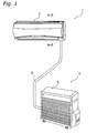
- Figure 1 shows the external appearance of an air conditioner 1 in which an embodiment of the present invention has been employed.
- the air conditioner 1 is a device that delivers conditioned (i.e., cooled, heated, dehumidified, etc.) air into a room to condition the air inside the room.
- the air conditioner 1 is provided with an indoor unit 2 installed on an upper section of a wall inside the room and an outdoor unit 3 installed outdoors.
- the outdoor unit 3 is provided with an outdoor air conditioning unit 5 that encloses an outdoor heat exchanger and an outdoor fan.
- the indoor unit 2 encloses an indoor heat exchanger and the outdoor air conditioning unit 5 encloses an outdoor heat exchanger. These heat exchangers together with the refrigerant pipe 6 connecting them constitute a refrigerant circuit.
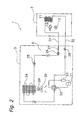
- the refrigerant circuit used in the air conditioner 1 is illustrated in the flow diagram of Figure 2.
- the indoor heat exchanger 11 is provided inside the indoor unit 2.
- the indoor heat exchanger 11 includes a heat exchanger tube that is folded back a plurality of times in the lengthwise direction and a plurality of fins through which the heat exchanger tube is passed.
- the indoor heat exchanger 11 exchanges heat with the air it contacts.
- a cross flow fan 12 is also provided inside the indoor unit 2 and serves to blow the air that has exchanged heat with the indoor heat exchanger 11 into the room.
- the cross flow fan 12 is cylindrical in shape and is provided with blades arranged on its circumferential surface so as to be parallel to the rotational axis thereof.
- the cross flow fan 12 generates an air flow in a direction that intersects with the rotational axis.
- the cross flow fan 12 is rotationally driven by a fan motor 13 provided inside the indoor unit 2.
- the outdoor air conditioning unit 5 is provided with a compressor 21, a four-way selector valve 22, an accumulator 23, an outdoor heat exchanger 24, and a pressure reducer 25 (see Figure 2).
- the four-way selector valve 22 is connected to the discharge side of the compressor 21.
- the accumulator 23 is connected to the intake side of the compressor 21.
- the outdoor heat exchanger 24 is connected to the four-way selector valve 22.
- the pressure reducer 25 is an electric powered expansion valve connected to the outdoor heat exchanger 24.
- the pressure reducer 25 is connected to a pipe 31 through a filter 26 and a liquid shut-off valve 27 and, thus, is connected to one end of the indoor heat exchanger 11 through the pipe 31.
- the four-way selector valve 22 is connected to a pipe 32 through a gas shut-off valve 28 and, thus, is connected to the other end of the indoor heat exchanger 11 through the pipe 32.
- These pipes 31, 32 are equivalent to the refrigerant pipe 6 shown in Figure 1.
- FIG. 3 A cross sectional view of the indoor unit 2 is shown in Figure 3.
- the previously described indoor heat exchanger 11 and the cross flow fan 12 are housed inside the casing 14 of the indoor unit 2.
- the indoor heat exchanger 11 is arranged so as to surround the front, top, and upper rear portions of the cross flow fan 12.
- the cross flow fan 12 draws air into the unit through intake openings 142. As the air moves toward the cross flow fan 12, it exchanges heat with the refrigerant inside the heat exchanger tube of the indoor heat exchanger 11.
- a drain pan 141 is provided below the indoor heat exchanger 11 to catch water droplets that form on the surface of the indoor heat exchanger 11 during the process of exchanging heat.
- the drain pan 141 has a drain hose (not shown) for discharging the water droplets caught to the outside.
- the drain pan 141 is constructed such that it catches water droplets and discharges the water droplets by means of the drain hose.
- An intake opening 142 made up of a plurality of slit-shaped openings is provided in an upper part of the casing 14.
- An outlet opening 143 that is long in the lengthwise direction of the indoor unit 2 is provided in a lower part of the casing 14.
- a horizontal flap 144 for determining the discharge direction of the air delivered into the room by the cross flow fan 12 is provided in the outlet opening 143.
- the horizontal flap 144 can rotate freely about a shaft 145 that is parallel to the lengthwise direction of the indoor unit 2.
- the horizontal flap 144 can determine the discharge direction of the air by being rotated by a flap motor 146 (see Figure 7), which is described later. As shown in Figure 4, the conditioned air is blown in an approximately horizontal direction when the edge part 144a of the horizontal flap 144 points in an approximately horizontal direction.
- the conditioned air is blown in an approximately vertical downward direction when the edge part 144a of the horizontal flap 144 points in an approximately vertical downward direction.
- the edge part 144a of the horizontal flap 144 touches an edge part of the casing 14 when the air conditioner 1 is not running. In this state, the horizontal flap 144 covers the outlet opening 143 almost completely.
- a propeller fan 29 for discharging air to the outside after the air has exchanged heat with the outdoor heat exchanger 24.
- the propeller fan 29 is rotationally driven by a propeller fan motor 30.
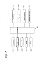
- the air conditioner 1 is also provided with a control unit 60. As shown in Figure 7, the control unit 60 is connected to the compressor 21, the four-way selector valve 22, the pressure reducer 25, a ROM 41, a RAM 42, the fan motor 13, the flap motor 146, a remote control 40, and a temperature sensor 43. The control unit 60 executes control of the pressure reducer 21, the four-way selector valve 22, the pressure reducer 25, the fan motor 13, the flap motor 146, etc.
- the ROM 41 stores control programs and various parameters.
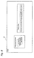
- the ROM 41 also stores the swing speed settings and swing modes of the horizontal flap 144 (see Figure 8).
- the swing speed settings are operating speeds for determining the swing speed of the horizontal flap 144. More specifically, the swing speed setting is selected from among a “high speed,” a “medium speed,” and a “high speed.” The “low speed” is the slowest swing speed and the "high speed” is the fastest swing speed.
- the control unit 60 rotates the flap motor 146 in such a manner as to swing the horizontal flap 144 at a speed corresponding to the selected swing speed setting.
- the swing modes are for determining whether or not the horizontal flap 144 will be swung or how it will be swung.
- constant speed mode the horizontal flap 144 is swung intermittently at a constant speed.
- stationary mode the horizontal flap 144 is stopped at a certain point (angle) during mid-swing and held stationary at that angle.
- comfort mode the swing speed of the horizontal flap 144 is changed in accordance with the room temperature (details discussed later).
- a room occupant transmits the desired mode to the control unit 60 with the remote control 40.
- the control unit 60 controls the swinging of the horizontal flap 144 using the transmitted mode.
- the remote control 40 is a user-operated device that transmits the room occupant's instructions to the air conditioner 1 so that the air conditioner 1 can be operated according to the wishes of the room occupant.
- the room occupant can use the remote control 40 to set the target temperature and to select the swing speed and swing mode of the horizontal flap 144.
- These instructions are transmitted from the remote control 40 to the control unit 60 and used for control of the various components.
- These instructions are also sent from the remote control 60 to the RAM 42 and stored in the RAM 42.
- the temperature sensor 43 is provided in the indoor unit 2 and serves to measure the temperature inside the room. The temperature sensor 43 transmits the measured temperature to the control unit 60.
- the control unit 60 checks which swing mode has been selected (step S201). If the stationary mode has been selected, the control unit 60 does not swing the horizontal flap 144 (step S202). If the constant speed mode has been selected, the control unit 60 sets the swing speed of the horizontal flap 144 to the "medium speed" (step S203). If the comfort mode has been selected, the control unit 60 determines if the room temperature is equal to or above 24 Celsius (step S204). If the room temperature is below 24 Celsius, the control unit 60 sets the swing speed of the horizontal flap 144 to the "low speed” (step S205). If the room temperature is equal to or above 24 Celsius, the control unit 60 sets the swing speed of the horizontal flap 144 to the "high speed” (step S206).
- the swing speed of the flap is changed according to the room temperature and the amount of time the delivered air contacts the room occupants during each swing (complete swing including return swing) is changed according to the room temperature. Therefore, the occurrence of situations in which the comfort level of the room occupants is degraded can be reduced by appropriately setting the room temperatures at which the swing speed is changed and the speed values to which the swing speed is changed.
Landscapes
- Engineering & Computer Science (AREA)
- General Engineering & Computer Science (AREA)
- Chemical & Material Sciences (AREA)
- Combustion & Propulsion (AREA)
- Mechanical Engineering (AREA)
- Physics & Mathematics (AREA)
- Signal Processing (AREA)
- Thermal Sciences (AREA)
- Fluid Mechanics (AREA)
- Fuzzy Systems (AREA)
- Mathematical Physics (AREA)
- Human Computer Interaction (AREA)
- Air Conditioning Control Device (AREA)
Abstract
Description
Claims (6)
- An air conditioner (1) capable of running in cooling mode and/or dehumidifying mode, the air conditioner being provided with:an air delivery unit (12, 13) that delivers conditioned air into a room;a flap (144) that determines the discharge direction of the air delivered from the air delivery unit (12, 13); anda control unit (60) that executes a first control to change the swing speed of the flap (144) in accordance with the room temperature.
- An air conditioner (1) as recited in claim 1, wherein
the first control changes the swing speed to a first swing speed when the room temperature is equal to or above a prescribed room temperature and changes the swing speed to a second swing speed when the room temperature is below the prescribed temperature; and
the first swing speed is slower than the second swing speed. - An air conditioner as recited in claim 2, wherein the control unit (60) can execute a second control that does not change the swing speed of the flap (144); and
there is further provided a selecting means (60) that selects either the first control or the second control. - An air conditioner (1) as recited in claim 3, wherein
the control unit (60) is also capable of executing a third control that swings the flap (144) at a constant speed at all times; and
the selecting means (60) selects among the first control, the second control, and the third control. - An air conditioner (1) as recited in any one of claims 1 to 4, wherein
the control unit (60) swings the horizontal flap (144) in an up and down direction. - A control method for an air conditioner that is provided with an air delivery unit (12, 13) for delivering conditioned air into a room and a flap (144) for determining the discharge direction of the air delivered from the air delivery unit (12, 13) and is capable of running in cooling mode and/or dehumidifying mode; the control method including:a first step in which the room temperature is measured; anda second step in which the swing speed of the flap (144) is changed in accordance with the room temperature.
Applications Claiming Priority (3)
| Application Number | Priority Date | Filing Date | Title |
|---|---|---|---|
| JP2002234698 | 2002-08-12 | ||
| JP2002234698A JP2004076974A (en) | 2002-08-12 | 2002-08-12 | Air conditioner and control method of air conditioner |
| PCT/JP2003/010183 WO2004016993A1 (en) | 2002-08-12 | 2003-08-08 | Air conditioner and method of controlling air conditioner |
Publications (3)
| Publication Number | Publication Date |
|---|---|
| EP1530008A1 true EP1530008A1 (en) | 2005-05-11 |
| EP1530008A4 EP1530008A4 (en) | 2008-04-02 |
| EP1530008B1 EP1530008B1 (en) | 2011-04-13 |
Family
ID=31884353
Family Applications (1)
| Application Number | Title | Priority Date | Filing Date |
|---|---|---|---|
| EP03788068A Expired - Lifetime EP1530008B1 (en) | 2002-08-12 | 2003-08-08 | Air conditioner and method of controlling air conditioner |
Country Status (10)
| Country | Link |
|---|---|
| US (1) | US7040105B2 (en) |
| EP (1) | EP1530008B1 (en) |
| JP (1) | JP2004076974A (en) |
| KR (1) | KR100527554B1 (en) |
| CN (1) | CN100356115C (en) |
| AT (1) | ATE505691T1 (en) |
| AU (1) | AU2003254916B2 (en) |
| DE (1) | DE60336728D1 (en) |
| ES (1) | ES2364045T3 (en) |
| WO (1) | WO2004016993A1 (en) |
Cited By (1)
| Publication number | Priority date | Publication date | Assignee | Title |
|---|---|---|---|---|
| RU2640707C2 (en) * | 2013-06-04 | 2018-01-11 | Гри Электрик Эпплайенсиз, Инк. оф Чжухай | Method of adjustment of air conditioner blinds |
Families Citing this family (14)
| Publication number | Priority date | Publication date | Assignee | Title |
|---|---|---|---|---|
| KR100672508B1 (en) | 2004-07-02 | 2007-01-24 | 엘지전자 주식회사 | Discharge airflow control method of indoor unit for air conditioner |
| KR100640801B1 (en) * | 2005-05-10 | 2006-11-02 | 엘지전자 주식회사 | Vane Control Method of Ceiling Air Conditioner |
| JP2007139227A (en) * | 2005-11-15 | 2007-06-07 | Sanyo Electric Co Ltd | Air conditioner |
| JP4165604B2 (en) * | 2006-07-31 | 2008-10-15 | ダイキン工業株式会社 | Air conditioning control device and air conditioning control method |
| JP4483990B2 (en) * | 2008-11-20 | 2010-06-16 | ダイキン工業株式会社 | Air conditioner |
| JP5304574B2 (en) * | 2009-09-28 | 2013-10-02 | ダイキン工業株式会社 | Control device |
| JP2011069592A (en) * | 2009-09-28 | 2011-04-07 | Daikin Industries Ltd | Control device |
| EP2484986B1 (en) * | 2009-09-28 | 2020-08-05 | Daikin Industries, Ltd. | Control device |
| JP5928038B2 (en) * | 2012-03-19 | 2016-06-01 | カシオ計算機株式会社 | Information processing apparatus and program |
| CN103574844B (en) * | 2013-10-25 | 2017-01-18 | 广东美的制冷设备有限公司 | Air conditioner and control method, control terminal and air conditioner system thereof |
| CN104374048B (en) * | 2014-10-29 | 2017-08-15 | 广东美的制冷设备有限公司 | The control method and control system of air conditioner wind direction |
| CN105135625B (en) * | 2015-07-16 | 2018-07-17 | 广东美的制冷设备有限公司 | A kind of air conditioner intelligent air blowing control method and system |
| KR102519931B1 (en) * | 2016-01-07 | 2023-04-11 | 삼성전자주식회사 | Air conditioner |
| JP6739218B2 (en) * | 2016-04-21 | 2020-08-12 | 日立ジョンソンコントロールズ空調株式会社 | Air conditioner |
Family Cites Families (16)
| Publication number | Priority date | Publication date | Assignee | Title |
|---|---|---|---|---|
| JPS601539B2 (en) * | 1979-10-09 | 1985-01-16 | 松下電器産業株式会社 | Blowout angle changing device |
| US4422571A (en) * | 1981-05-22 | 1983-12-27 | Hoffman Controls Corp. | Proportional motor drive control |
| JPH01306761A (en) * | 1988-06-03 | 1989-12-11 | Matsushita Refrig Co Ltd | Variable air flow rate controller |
| JP2597012B2 (en) * | 1989-09-11 | 1997-04-02 | 三菱重工業株式会社 | Air direction change device for air conditioner |
| JPH04349021A (en) * | 1990-08-02 | 1992-12-03 | Mazda Motor Corp | Car air conditioner |
| JP3085737B2 (en) * | 1991-07-17 | 2000-09-11 | ダイキン工業株式会社 | Air conditioner |
| JPH0642797A (en) * | 1992-07-28 | 1994-02-18 | Daikin Ind Ltd | Operation control device for air conditioner |
| JPH08136034A (en) * | 1994-11-14 | 1996-05-31 | Hitachi Ltd | Air conditioner |
| US5775989A (en) * | 1995-08-21 | 1998-07-07 | Samsung Electronics Co., Ltd. | Methods of and apparatus for adjusting air flow control louver |
| JP3331836B2 (en) * | 1995-09-29 | 2002-10-07 | 松下電器産業株式会社 | Control device for air conditioner |
| JPH09133389A (en) * | 1995-11-08 | 1997-05-20 | Sanyo Electric Co Ltd | Air conditioner |
| JP3952597B2 (en) * | 1997-08-08 | 2007-08-01 | 株式会社デンソー | Air conditioner for vehicles |
| KR19990042899A (en) * | 1997-11-28 | 1999-06-15 | 구자홍 | Wind direction control method of air conditioner |
| KR100315783B1 (en) * | 1999-03-24 | 2001-12-12 | 구자홍 | Cool air flow control method &the apparatus of air-conditioner |
| JP3352428B2 (en) * | 1999-08-04 | 2002-12-03 | 松下電器産業株式会社 | Wind direction control method for air conditioner |
| JP2001153430A (en) * | 1999-12-01 | 2001-06-08 | Matsushita Electric Ind Co Ltd | Air conditioner wind direction control method |
-
2002
- 2002-08-12 JP JP2002234698A patent/JP2004076974A/en active Pending
-
2003
- 2003-08-08 WO PCT/JP2003/010183 patent/WO2004016993A1/en not_active Ceased
- 2003-08-08 CN CNB03800982XA patent/CN100356115C/en not_active Expired - Fee Related
- 2003-08-08 EP EP03788068A patent/EP1530008B1/en not_active Expired - Lifetime
- 2003-08-08 US US10/493,863 patent/US7040105B2/en not_active Expired - Fee Related
- 2003-08-08 KR KR10-2004-7004703A patent/KR100527554B1/en not_active Expired - Fee Related
- 2003-08-08 DE DE60336728T patent/DE60336728D1/en not_active Expired - Lifetime
- 2003-08-08 AU AU2003254916A patent/AU2003254916B2/en not_active Ceased
- 2003-08-08 ES ES03788068T patent/ES2364045T3/en not_active Expired - Lifetime
- 2003-08-08 AT AT03788068T patent/ATE505691T1/en not_active IP Right Cessation
Cited By (1)
| Publication number | Priority date | Publication date | Assignee | Title |
|---|---|---|---|---|
| RU2640707C2 (en) * | 2013-06-04 | 2018-01-11 | Гри Электрик Эпплайенсиз, Инк. оф Чжухай | Method of adjustment of air conditioner blinds |
Also Published As
| Publication number | Publication date |
|---|---|
| KR100527554B1 (en) | 2005-11-09 |
| KR20040039462A (en) | 2004-05-10 |
| CN100356115C (en) | 2007-12-19 |
| DE60336728D1 (en) | 2011-05-26 |
| ATE505691T1 (en) | 2011-04-15 |
| US20040244391A1 (en) | 2004-12-09 |
| AU2003254916B2 (en) | 2005-07-21 |
| US7040105B2 (en) | 2006-05-09 |
| AU2003254916A1 (en) | 2004-03-03 |
| EP1530008A4 (en) | 2008-04-02 |
| JP2004076974A (en) | 2004-03-11 |
| CN1708661A (en) | 2005-12-14 |
| WO2004016993A1 (en) | 2004-02-26 |
| ES2364045T3 (en) | 2011-08-23 |
| EP1530008B1 (en) | 2011-04-13 |
Similar Documents
| Publication | Publication Date | Title |
|---|---|---|
| CN109405169B (en) | Air conditioner indoor unit and control method thereof | |
| JP5585556B2 (en) | Air conditioner | |
| EP1530008B1 (en) | Air conditioner and method of controlling air conditioner | |
| CN101825328B (en) | Air conditioner and its control method | |
| US20120097748A1 (en) | Air-conditioning apparatus | |
| US10830484B2 (en) | Air-conditioning apparatus | |
| JPS60188743A (en) | Control of heat pump type air conditioner | |
| KR20130137136A (en) | Air conditioning apparatus | |
| EP2169320B1 (en) | Air conditioner | |
| JP4133100B2 (en) | Air conditioner and control method of air conditioner | |
| JP3815471B2 (en) | Air conditioner | |
| JP2021085565A (en) | Indoor unit of air conditioner and air conditioning system | |
| JP4215035B2 (en) | Air conditioner and control method thereof | |
| JP3815470B2 (en) | Air conditioner | |
| CN108731219A (en) | Air-conditioner control method, indoor unit and air conditioner | |
| CN110637199A (en) | Air Conditioning System | |
| JP4483944B2 (en) | Air conditioner | |
| JP2013050249A (en) | Air conditioning system | |
| JP2004125230A (en) | Heating operation method of air conditioning system | |
| JP2001201149A (en) | Air conditioner | |
| JPH05240492A (en) | Device for controlling operation of heat-pump type air conditioner |
Legal Events
| Date | Code | Title | Description |
|---|---|---|---|
| PUAI | Public reference made under article 153(3) epc to a published international application that has entered the european phase |
Free format text: ORIGINAL CODE: 0009012 |
|
| 17P | Request for examination filed |
Effective date: 20040505 |
|
| AK | Designated contracting states |
Kind code of ref document: A1 Designated state(s): AT BE BG CH CY CZ DE DK EE ES FI FR GB GR HU IE IT LI LU MC NL PT RO SE SI SK TR |
|
| AX | Request for extension of the european patent |
Extension state: AL LT LV MK |
|
| DAX | Request for extension of the european patent (deleted) | ||
| A4 | Supplementary search report drawn up and despatched |
Effective date: 20080228 |
|
| 17Q | First examination report despatched |
Effective date: 20090414 |
|
| GRAP | Despatch of communication of intention to grant a patent |
Free format text: ORIGINAL CODE: EPIDOSNIGR1 |
|
| GRAS | Grant fee paid |
Free format text: ORIGINAL CODE: EPIDOSNIGR3 |
|
| GRAA | (expected) grant |
Free format text: ORIGINAL CODE: 0009210 |
|
| AK | Designated contracting states |
Kind code of ref document: B1 Designated state(s): AT BE BG CH CY CZ DE DK EE ES FI FR GB GR HU IE IT LI LU MC NL PT RO SE SI SK TR |
|
| REG | Reference to a national code |
Ref country code: GB Ref legal event code: FG4D |
|
| REG | Reference to a national code |
Ref country code: CH Ref legal event code: EP |
|
| REG | Reference to a national code |
Ref country code: IE Ref legal event code: FG4D |
|
| REF | Corresponds to: |
Ref document number: 60336728 Country of ref document: DE Date of ref document: 20110526 Kind code of ref document: P |
|
| REG | Reference to a national code |
Ref country code: DE Ref legal event code: R096 Ref document number: 60336728 Country of ref document: DE Effective date: 20110526 |
|
| REG | Reference to a national code |
Ref country code: NL Ref legal event code: VDEP Effective date: 20110413 |
|
| REG | Reference to a national code |
Ref country code: ES Ref legal event code: FG2A Ref document number: 2364045 Country of ref document: ES Kind code of ref document: T3 Effective date: 20110823 |
|
| PG25 | Lapsed in a contracting state [announced via postgrant information from national office to epo] |
Ref country code: PT Free format text: LAPSE BECAUSE OF FAILURE TO SUBMIT A TRANSLATION OF THE DESCRIPTION OR TO PAY THE FEE WITHIN THE PRESCRIBED TIME-LIMIT Effective date: 20110816 Ref country code: SE Free format text: LAPSE BECAUSE OF FAILURE TO SUBMIT A TRANSLATION OF THE DESCRIPTION OR TO PAY THE FEE WITHIN THE PRESCRIBED TIME-LIMIT Effective date: 20110413 |
|
| PG25 | Lapsed in a contracting state [announced via postgrant information from national office to epo] |
Ref country code: AT Free format text: LAPSE BECAUSE OF FAILURE TO SUBMIT A TRANSLATION OF THE DESCRIPTION OR TO PAY THE FEE WITHIN THE PRESCRIBED TIME-LIMIT Effective date: 20110413 Ref country code: BE Free format text: LAPSE BECAUSE OF FAILURE TO SUBMIT A TRANSLATION OF THE DESCRIPTION OR TO PAY THE FEE WITHIN THE PRESCRIBED TIME-LIMIT Effective date: 20110413 Ref country code: GR Free format text: LAPSE BECAUSE OF FAILURE TO SUBMIT A TRANSLATION OF THE DESCRIPTION OR TO PAY THE FEE WITHIN THE PRESCRIBED TIME-LIMIT Effective date: 20110714 Ref country code: CY Free format text: LAPSE BECAUSE OF FAILURE TO SUBMIT A TRANSLATION OF THE DESCRIPTION OR TO PAY THE FEE WITHIN THE PRESCRIBED TIME-LIMIT Effective date: 20110413 Ref country code: FI Free format text: LAPSE BECAUSE OF FAILURE TO SUBMIT A TRANSLATION OF THE DESCRIPTION OR TO PAY THE FEE WITHIN THE PRESCRIBED TIME-LIMIT Effective date: 20110413 Ref country code: SI Free format text: LAPSE BECAUSE OF FAILURE TO SUBMIT A TRANSLATION OF THE DESCRIPTION OR TO PAY THE FEE WITHIN THE PRESCRIBED TIME-LIMIT Effective date: 20110413 |
|
| PG25 | Lapsed in a contracting state [announced via postgrant information from national office to epo] |
Ref country code: NL Free format text: LAPSE BECAUSE OF FAILURE TO SUBMIT A TRANSLATION OF THE DESCRIPTION OR TO PAY THE FEE WITHIN THE PRESCRIBED TIME-LIMIT Effective date: 20110413 |
|
| PG25 | Lapsed in a contracting state [announced via postgrant information from national office to epo] |
Ref country code: EE Free format text: LAPSE BECAUSE OF FAILURE TO SUBMIT A TRANSLATION OF THE DESCRIPTION OR TO PAY THE FEE WITHIN THE PRESCRIBED TIME-LIMIT Effective date: 20110413 Ref country code: CZ Free format text: LAPSE BECAUSE OF FAILURE TO SUBMIT A TRANSLATION OF THE DESCRIPTION OR TO PAY THE FEE WITHIN THE PRESCRIBED TIME-LIMIT Effective date: 20110413 |
|
| PLBE | No opposition filed within time limit |
Free format text: ORIGINAL CODE: 0009261 |
|
| STAA | Information on the status of an ep patent application or granted ep patent |
Free format text: STATUS: NO OPPOSITION FILED WITHIN TIME LIMIT |
|
| PG25 | Lapsed in a contracting state [announced via postgrant information from national office to epo] |
Ref country code: DK Free format text: LAPSE BECAUSE OF FAILURE TO SUBMIT A TRANSLATION OF THE DESCRIPTION OR TO PAY THE FEE WITHIN THE PRESCRIBED TIME-LIMIT Effective date: 20110413 Ref country code: RO Free format text: LAPSE BECAUSE OF FAILURE TO SUBMIT A TRANSLATION OF THE DESCRIPTION OR TO PAY THE FEE WITHIN THE PRESCRIBED TIME-LIMIT Effective date: 20110413 Ref country code: SK Free format text: LAPSE BECAUSE OF FAILURE TO SUBMIT A TRANSLATION OF THE DESCRIPTION OR TO PAY THE FEE WITHIN THE PRESCRIBED TIME-LIMIT Effective date: 20110413 |
|
| 26N | No opposition filed |
Effective date: 20120116 |
|
| PG25 | Lapsed in a contracting state [announced via postgrant information from national office to epo] |
Ref country code: MC Free format text: LAPSE BECAUSE OF NON-PAYMENT OF DUE FEES Effective date: 20110831 |
|
| REG | Reference to a national code |
Ref country code: CH Ref legal event code: PL |
|
| PG25 | Lapsed in a contracting state [announced via postgrant information from national office to epo] |
Ref country code: LI Free format text: LAPSE BECAUSE OF NON-PAYMENT OF DUE FEES Effective date: 20110831 Ref country code: CH Free format text: LAPSE BECAUSE OF NON-PAYMENT OF DUE FEES Effective date: 20110831 |
|
| REG | Reference to a national code |
Ref country code: DE Ref legal event code: R097 Ref document number: 60336728 Country of ref document: DE Effective date: 20120116 |
|
| REG | Reference to a national code |
Ref country code: IE Ref legal event code: MM4A |
|
| PG25 | Lapsed in a contracting state [announced via postgrant information from national office to epo] |
Ref country code: IE Free format text: LAPSE BECAUSE OF NON-PAYMENT OF DUE FEES Effective date: 20110808 |
|
| PG25 | Lapsed in a contracting state [announced via postgrant information from national office to epo] |
Ref country code: LU Free format text: LAPSE BECAUSE OF NON-PAYMENT OF DUE FEES Effective date: 20110808 |
|
| PG25 | Lapsed in a contracting state [announced via postgrant information from national office to epo] |
Ref country code: BG Free format text: LAPSE BECAUSE OF FAILURE TO SUBMIT A TRANSLATION OF THE DESCRIPTION OR TO PAY THE FEE WITHIN THE PRESCRIBED TIME-LIMIT Effective date: 20110713 |
|
| PG25 | Lapsed in a contracting state [announced via postgrant information from national office to epo] |
Ref country code: TR Free format text: LAPSE BECAUSE OF FAILURE TO SUBMIT A TRANSLATION OF THE DESCRIPTION OR TO PAY THE FEE WITHIN THE PRESCRIBED TIME-LIMIT Effective date: 20110413 |
|
| PG25 | Lapsed in a contracting state [announced via postgrant information from national office to epo] |
Ref country code: HU Free format text: LAPSE BECAUSE OF FAILURE TO SUBMIT A TRANSLATION OF THE DESCRIPTION OR TO PAY THE FEE WITHIN THE PRESCRIBED TIME-LIMIT Effective date: 20110413 |
|
| REG | Reference to a national code |
Ref country code: FR Ref legal event code: PLFP Year of fee payment: 13 |
|
| REG | Reference to a national code |
Ref country code: FR Ref legal event code: PLFP Year of fee payment: 14 |
|
| PGFP | Annual fee paid to national office [announced via postgrant information from national office to epo] |
Ref country code: DE Payment date: 20160802 Year of fee payment: 14 Ref country code: GB Payment date: 20160803 Year of fee payment: 14 Ref country code: IT Payment date: 20160822 Year of fee payment: 14 |
|
| PGFP | Annual fee paid to national office [announced via postgrant information from national office to epo] |
Ref country code: FR Payment date: 20160712 Year of fee payment: 14 |
|
| PGFP | Annual fee paid to national office [announced via postgrant information from national office to epo] |
Ref country code: ES Payment date: 20160712 Year of fee payment: 14 |
|
| REG | Reference to a national code |
Ref country code: DE Ref legal event code: R079 Ref document number: 60336728 Country of ref document: DE Free format text: PREVIOUS MAIN CLASS: F24F0011020000 Ipc: F24F0011890000 |
|
| REG | Reference to a national code |
Ref country code: DE Ref legal event code: R119 Ref document number: 60336728 Country of ref document: DE |
|
| GBPC | Gb: european patent ceased through non-payment of renewal fee |
Effective date: 20170808 |
|
| REG | Reference to a national code |
Ref country code: FR Ref legal event code: ST Effective date: 20180430 |
|
| PG25 | Lapsed in a contracting state [announced via postgrant information from national office to epo] |
Ref country code: DE Free format text: LAPSE BECAUSE OF NON-PAYMENT OF DUE FEES Effective date: 20180301 Ref country code: GB Free format text: LAPSE BECAUSE OF NON-PAYMENT OF DUE FEES Effective date: 20170808 |
|
| PG25 | Lapsed in a contracting state [announced via postgrant information from national office to epo] |
Ref country code: FR Free format text: LAPSE BECAUSE OF NON-PAYMENT OF DUE FEES Effective date: 20170831 Ref country code: IT Free format text: LAPSE BECAUSE OF NON-PAYMENT OF DUE FEES Effective date: 20170808 |
|
| REG | Reference to a national code |
Ref country code: ES Ref legal event code: FD2A Effective date: 20181029 |
|
| PG25 | Lapsed in a contracting state [announced via postgrant information from national office to epo] |
Ref country code: ES Free format text: LAPSE BECAUSE OF NON-PAYMENT OF DUE FEES Effective date: 20170809 |