EP1529984A2 - Motor with reduction mechanism and power seat motor with reduction mechanism - Google Patents
Motor with reduction mechanism and power seat motor with reduction mechanism Download PDFInfo
- Publication number
- EP1529984A2 EP1529984A2 EP04026738A EP04026738A EP1529984A2 EP 1529984 A2 EP1529984 A2 EP 1529984A2 EP 04026738 A EP04026738 A EP 04026738A EP 04026738 A EP04026738 A EP 04026738A EP 1529984 A2 EP1529984 A2 EP 1529984A2
- Authority
- EP
- European Patent Office
- Prior art keywords
- shaft
- motor
- gear
- worm
- armature shaft
- Prior art date
- Legal status (The legal status is an assumption and is not a legal conclusion. Google has not performed a legal analysis and makes no representation as to the accuracy of the status listed.)
- Withdrawn
Links
Images


Classifications
-
- H—ELECTRICITY
- H02—GENERATION; CONVERSION OR DISTRIBUTION OF ELECTRIC POWER
- H02K—DYNAMO-ELECTRIC MACHINES
- H02K7/00—Arrangements for handling mechanical energy structurally associated with dynamo-electric machines, e.g. structural association with mechanical driving motors or auxiliary dynamo-electric machines
- H02K7/08—Structural association with bearings
- H02K7/081—Structural association with bearings specially adapted for worm gear drives
-
- B—PERFORMING OPERATIONS; TRANSPORTING
- B60—VEHICLES IN GENERAL
- B60N—SEATS SPECIALLY ADAPTED FOR VEHICLES; VEHICLE PASSENGER ACCOMMODATION NOT OTHERWISE PROVIDED FOR
- B60N2/00—Seats specially adapted for vehicles; Arrangement or mounting of seats in vehicles
- B60N2/02—Seats specially adapted for vehicles; Arrangement or mounting of seats in vehicles the seat or part thereof being movable, e.g. adjustable
- B60N2/0224—Non-manual adjustments, e.g. with electrical operation
- B60N2/02246—Electric motors therefor
-
- B—PERFORMING OPERATIONS; TRANSPORTING
- B60—VEHICLES IN GENERAL
- B60N—SEATS SPECIALLY ADAPTED FOR VEHICLES; VEHICLE PASSENGER ACCOMMODATION NOT OTHERWISE PROVIDED FOR
- B60N2/00—Seats specially adapted for vehicles; Arrangement or mounting of seats in vehicles
- B60N2/02—Seats specially adapted for vehicles; Arrangement or mounting of seats in vehicles the seat or part thereof being movable, e.g. adjustable
- B60N2/04—Seats specially adapted for vehicles; Arrangement or mounting of seats in vehicles the seat or part thereof being movable, e.g. adjustable the whole seat being movable
- B60N2/06—Seats specially adapted for vehicles; Arrangement or mounting of seats in vehicles the seat or part thereof being movable, e.g. adjustable the whole seat being movable slidable
- B60N2/067—Seats specially adapted for vehicles; Arrangement or mounting of seats in vehicles the seat or part thereof being movable, e.g. adjustable the whole seat being movable slidable by linear actuators, e.g. linear screw mechanisms
-
- F—MECHANICAL ENGINEERING; LIGHTING; HEATING; WEAPONS; BLASTING
- F16—ENGINEERING ELEMENTS AND UNITS; GENERAL MEASURES FOR PRODUCING AND MAINTAINING EFFECTIVE FUNCTIONING OF MACHINES OR INSTALLATIONS; THERMAL INSULATION IN GENERAL
- F16H—GEARING
- F16H1/00—Toothed gearings for conveying rotary motion
- F16H1/02—Toothed gearings for conveying rotary motion without gears having orbital motion
- F16H1/20—Toothed gearings for conveying rotary motion without gears having orbital motion involving more than two intermeshing members
- F16H1/22—Toothed gearings for conveying rotary motion without gears having orbital motion involving more than two intermeshing members with a plurality of driving or driven shafts; with arrangements for dividing torque between two or more intermediate shafts
- F16H1/222—Toothed gearings for conveying rotary motion without gears having orbital motion involving more than two intermeshing members with a plurality of driving or driven shafts; with arrangements for dividing torque between two or more intermediate shafts with non-parallel axes
- F16H1/225—Toothed gearings for conveying rotary motion without gears having orbital motion involving more than two intermeshing members with a plurality of driving or driven shafts; with arrangements for dividing torque between two or more intermediate shafts with non-parallel axes with two or more worm and worm-wheel gearings
-
- F—MECHANICAL ENGINEERING; LIGHTING; HEATING; WEAPONS; BLASTING
- F16—ENGINEERING ELEMENTS AND UNITS; GENERAL MEASURES FOR PRODUCING AND MAINTAINING EFFECTIVE FUNCTIONING OF MACHINES OR INSTALLATIONS; THERMAL INSULATION IN GENERAL
- F16H—GEARING
- F16H57/00—General details of gearing
- F16H57/02—Gearboxes; Mounting gearing therein
- F16H57/021—Shaft support structures, e.g. partition walls, bearing eyes, casing walls or covers with bearings
- F16H2057/0213—Support of worm gear shafts
-
- Y—GENERAL TAGGING OF NEW TECHNOLOGICAL DEVELOPMENTS; GENERAL TAGGING OF CROSS-SECTIONAL TECHNOLOGIES SPANNING OVER SEVERAL SECTIONS OF THE IPC; TECHNICAL SUBJECTS COVERED BY FORMER USPC CROSS-REFERENCE ART COLLECTIONS [XRACs] AND DIGESTS
- Y10—TECHNICAL SUBJECTS COVERED BY FORMER USPC
- Y10T—TECHNICAL SUBJECTS COVERED BY FORMER US CLASSIFICATION
- Y10T74/00—Machine element or mechanism
- Y10T74/19—Gearing
- Y10T74/19642—Directly cooperating gears
- Y10T74/19698—Spiral
- Y10T74/19828—Worm
Definitions
- the present invention relates to a motor with a reduction mechanism suitable for use as, for example, a wiper motor or a power window motor and to a power seat motor with a reduction mechanism for moving up and down a seat.
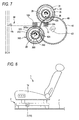
- a vehicle seat 1 is mounted on the floor F in the interior of a vehicle via a displacement mechanism 2 and the seat o is driven to move up and down by a power seat motor 3 used in the displacement mechanism 2.
- the power seat motor 3 has a motor shaft 3b projecting from a motor case 3a and rotatably supported by the worm-mounting cylindrical portion 4a of a gear case 4, a worm 6 coupled to the front end portion of the motor shaft 3b via a square column-like coupling shaft 5, a worm wheel 7 rotatably supported in the worm wheel mounting recess 4b of the gear case 4 and meshing with the worm 6, an output shaft 8 concentric and integral with the worm wheel 7, and a leaf spring 9 detachably mounted in the front-end opening portion of the worm- mounting cylindrical portion 4a and used for press-urging the semispherical front end portion 6a of the worm 6 toward the motor shaft 3b.
- the seat elevating mechanism (not shown) of the displacement mechanism 2 is coupled to the output shaft 8. Consequently, while the motor shaft 3b is rotating forward or reversely, the forward or reverse rotation of the worm 6 and the worm wheel 7 is reduced before being transmitted to the output shaft 8, so that the seat elevating mechanism is driven to move up or down the seat 1a.
- the conventional power seat motor 3 it has been arrange to prevent an unusual sound (noise) from being produced between the worm 6 and the worm wheel 7 by press-urging the semispherical front end portion 6a of the worm 6 toward the motor shaft 3b with the leaf spring 9 to eliminate the play in the thrust direction of the worm 6 due to a backlash between the worm 6 and the worm wheel 7.
- the leaf spring 9 is detachably mounted in the front-end opening portion of the worm- mounting cylindrical portion 4a, the worm-mounting cylindrical portion 4a becomes longer axially, thus making the whole body of the power seat motor 3 greater in size.
- An object of the invention made to solve the foregoing problems is to provide a small-sized motor with a reduction mechanism and a power seat motor with a reduction mechanism, which motors are simple in construction and capable of preventing an unusual sound frombeing generated from each tooth intermeshing portion in a case that the motor adopts a double-reduction mechanism having an output gear meshing with each large-diameter gear of a pair of counter gears respectively meshing with a pair of worms formed on a motor shaft with the thread directions of screws oriented opposite to each other and even in a case that a great fluctuation in load acts on the motor shaft such that the load changes from one load (a plus load) hindering the rotation of the motor shaft to the other load (a minus load) aiding the rotation of the motor shaft.
- the motor with the reduction mechanism is configured such that the recess is formed in the axial direction of the motor shaft from the end face of the back end of the motor shaft; the spring member elastically deformable in the axial direction of the motor shaft is housed in the recess; the slide member is slidably housed in the recess; the front end portion of the slide member is pressed to contact the inner face of the end portion of the motor case by the elastic force of the spring member; and the thrust force oriented in the direction of the front end of the motor shaft is always generated in the motor shaft by the resilient force of the spring member.
- the spring member and the slide member together with the motor shaft can smoothly be rotated by means of a simple construction moreover stable thrust force is applicable to the motor shaft in the direction of the front end of the armature shaft.
- Fig. 1 is a plan view of a motor with a reduction mechanism according to the embodiment of the invention
- Fig. 2, a sectional view of the motor
- Fig. 3, a plan view of a state in which the gear case of the motor has been removed
- Fig. 4 an enlarged sectional view of the principal part of the motor
- Fig. 5, a diagram illustrating a state in which a motor shaft for use in the motor is unrotated
- Fig. 6, a diagram illustrating a state in which the motor shaft for use in the motor is rotating forward
- Fig. 7, a diagram illustrating a state in which themotorshaftofthemotorisrotatingreversely.
- the vehicle seat (power seat) 1 shown in Fig. 8, presented for explaining the vehicle sheet having the conventional motor is also used for explaining the present invention.
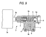
- a power seat motor 10 with a reduction mechanism (a motor with a reduction mechanism) has a substantially cylindrical yoke (motor case) 11 with one end side opened, and a gear case 21 with a flange portion 11b around the opening end 11a of the yoke 11 being fixedly tightened via machine screws.
- a pair of magnets 12 and 12 are secured to the inner peripheral face 11c of the yoke 11 with an adhesive agent or the like.
- an armature shaft (motor shaft) 14 is rotatably supported by a radial bearing 13a fitted into a closed-end cylindrical portion 11d at the other end of the yoke 11 and radial bearings 13b and 13c fitted into the vicinity of both ends of the shaft hole 22 of the gear case 21.
- the armature shaft 14 has a first worm (worm) 15 and a second worm (worm) 150 formed in the vicinity of the front end 14a of the armature shaft with the thread directions of screws oriented opposite to each other.
- the first worm 15 and the second worm 150 are used to form the pair of worms.
- An armature 16 is mounted in a position opposite to the pair of magnets 12 and 12 of the armature shaft 14.
- the armature 16 is fixed to the vicinity of the back end 14b of the armature shaft 14 and has an armature core 16a having coil-winding portions 16b with a predetermined number of slots and an armature coil 16c wound on the coil-winding portions 16b of the armature core 16a.
- a commutator 17 is fixed to a position opposite to the boundary portion between the yoke 11 of the armature shaft 14 and the gear case 21.
- the commutator 17 has commutator bars 17a equal in number to the coil-winding portions 16b of the armature core 16a, and each of the commutator bars 17a is electrically connected to the armature coil 16c.
- the opening end of the shaft hole 22 of the gear case 21 forms a large-diameter hole portion 22a, and a pair of brushes 19 and 19 are mounted to a position opposite to the commutator 17 in the large-diameter hole portion 22a so that the pair of brushes are brought into contact with the respective commutator bars 17a.
- Each of the brushes 19 is electrically connected to a motor control circuit (not shown). Switching the on-off of each switch out of a pair of switches of the motor control circuit causes an electric current to flow into the armature 16, so that the armature shaft 14 is rotated forward or reversely.
- the shaft hole 22 is formed substantially in the center of the gear case 21 and a depressed reduction-mechanism housing portion 23 is so formed as to communicate with the shaft hole 22.
- Cylindrical bosses (thrust bearings for counter gears) 24 and 24' are formed in a projected condition integrally in a predetermined position where the pair of worms 15 and 150 on the bottom wall of the reduction-mechanism housing portion 23 are sandwiched.
- circular recesses 25 and 25' are formed in the center of and in the respective cylindrical bosses 24 and 24'.
- the lower parts of metal pin-like pivots 26 and 26' are press-fitted into the respective recesses 25 and 25'.
- a first counter gear (counter gear) 30 is rotatably supported by the pivot 26 and a second counter gear 300 is rotatably supported by the pivot 26'.
- a circular hole 27a is as shown in Fig. 3 formed in a position a little to the right of the front end of the worm 15 of the bottom wall of the reduction-mechanism housing portion 23.
- a substantially annular rib 27b is formed in a projected condition integrally therewith around the circular hole 27a.
- the lower end of the cylindrical portion 41 of an output gear 40 is rotatably supported in the substantially annular rib 27b via a radial bearing 28a.
- a substantially triangular platelike plastic gear case cover 29 securely tightened with machine screws 20b.
- Circular recesses 29a and 29a' are formed in positions opposite to the respective recesses 25 and 25' of the reduction-mechanism housing portion 23 of the gear case cover 29.
- the upper part of the pivot 26 is press-fitted into the recess 29a and the upper part of the pivot 26' is press-fitted into the recess 29a'.
- a circular hole 29b is formed in a position opposite to the circular hole 27a of the reduction-mechanism housing portion 23 of the gear case cover 29.
- the upper end of the cylindrical portion 41 of the output gear 40 is rotatably supported in the circular hole 29b via a thrust-cum-radial bearing 28b.
- the pair of worms 15 and 150 and the pair of counter gears 30 and 300 and the output gear 40 are housed in the reduction-mechanism housing portion 23 of the gear case 22 to form a double-reduction mechanism.
- the first counter gear 30 is formed of a large-diameter plastic gear 31 and a first small-diameter metal gear 35 concentric with the large-diameter gear 31.
- a tooth part 32 meshing with the first worm 15 is formed on the outer periphery of the large-diameter gear 31 and an inside spline 33 is formed on the inner periphery of the large-diameter gear 31.
- a tooth part 36 meshing with the tooth part 42 of the output gear 40 and an outside spline 37 meshing with the inside spline 33 of the large-diameter gear 31 are formed on the outer periphery of the first small-diameter gear 35 are integrally formed in the axial direction in a concentric, difference-in-level form.
- fixing the large-diameter gear 31 relatively to the first small-diameter gear 35 is made by insert molding when the large-diameter plastic gear 31 is formed by molding.
- the second counter gear 300 is formed of a large-diameter plastic gear 310 and a second small-diameter metal gear 350 concentric with the large-diameter gear 310.
- a tooth part 320 meshing with the second worm 150 is formed on the outer periphery of the large-diameter gear 310, and the inside spline 33 is formed on the inner periphery of the large-diameter gear 310. Further, a tooth part 360 meshing with the tooth part 42 of the output gear 40 and the outside spline 37 meshing with the inside spline 33 of the large-diameter gear 310 are formed on the outer periphery of the second small-diameter gear 350 are integrally formed in the axial direction in a concentric, difference-in-level form. Inthiscase, fixing the large-diameter gear 310 relatively to the second small-diameter gear 350 is made by insert molding when the second large-diameter plastic gear 310 is formed by molding.
- an output shaft 43 is fixed in the cylindrical portion 41 of the output gear 40, and the seat elevating mechanism (not shown) of the displacement mechanism 2 of a vehicle seat 1 is coupled to a portion projected outside from the gear case 21 of the output shaft 43, whereby the seat elevating mechanism is driven to move a seat 1a up or down when the armature shaft 14 is rotated forward or reversely.
- the output shaft 43 coupled to the output gear 40 is driven to move up the seat 1a when the armature shaft 14 is rotated forward and to move down the seat 1a when the armature shaft 14 is rotated reversely.
- a cylindrical recess 14c circular in section is formed from the end face 14f of the back end 14b of the armature shaft 14 in the axial direction of the armature shaft 14, and a metal helical compression spring 51 as a spring member elastically deformable in the axial direction of the armature shaft 14 is housed in the cylindrical recess 14c, so that one end portion of the helical compression spring 51 is made to contact the base 14d of the cylindrical recess 14c, a plastic columnar slide member 52 being housed in the cylindrical recess 14c as well.
- the front end portion 52b of the slide member 52 is projected outside from the opening end 14e of the cylindrical recess 14 by the elastic force of the helical compression spring 51 disposed between the base 14d of the cylindrical recess 14c formed in the armature shaft 14 and the end face 52a of the back end portion of the slide member 52 and pressed to contact the base portion (inner face of the end portion of the motor case) 11e of the closed-end cylindrical portion 11d of the yoke 11, whereby the thrust force directed to the front end 14a of the armature shaft 14 is always generated in the armature shaft 14.
- the front end portion 52b of the slide member 52 is made semispherical in configuration and grease (semisolid oil lubricant) 53 is disposed between the top portion 52c of,the semispherical front end portion 52b and the base portion 11e of the closed-end cylindrical portion 11d.
- the large-diameter gears 31 and 310 of the pair of counter gears 30 and 300 are made to mesh with the pair of worms 15 and 150 formed in the vicinity of the front end 14a of the armature shaft 14 with the thread directions of screws oriented opposite to each other in order to make the motor shaft rotate forward or reversely, the direction of the thrust load of the armature shaft 14 oriented by causing the first worm 15 to mesh with the first counter gear 30 and the direction of the thrust load of the armature shaft 14 oriented by causing the second worm 150 to mesh with the second counter gear 301 are oriented opposite to each other and canceled out each other.
- thrust bearings for pivotably supporting both edges faces 14a1 and 14f of the armature shaft 14 are not necessary, so that such thrust bearings as to rotatably support the solid first counter gear 30 and the solid second counter gear 300 with precision can also be dispensed with.
- play in the thrust direction of the armature shaft 14 of the motor 10 due to a backlash between the tooth parts of each tooth intermeshing portion is eliminated, so that the armature shaft 14 can smoothly be rotated forward or reversely.
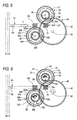
- a position B is a position to which the end face 14f of the back end 14b of the armature shaft 14 is movable when force opposite in direction to the direction F is applied from the outside while the armature shaft 14 is unrelated.
- the distance from the position A to the position B corresponds to the backlash produced in each tooth part.
- the state in which the first worm 15 and the first counter gear 30 are meshing with each other is such that the lateral tooth side 32a on one side of the tooth part 32 of the first counter gear 30 is in contact with the first worm 15 and the state in which the second worm 150 and the second counter gear 300 are meshing with each other is such that the lateral tooth side 320a on one side of the tooth part 320 of the second counter gear 300 is in contact with the second worm 150.
- the state in which the first small-diameter gear 35 and the output gear 40 are meshing with each other is such that the lateral tooth side 42a on one side of the tooth part 42 of the output gear 40 is in contact with the first small-diameter gear 35 and the state in which the second small-diameter gear 350 and the output gear 40 are meshing with each other is such that the lateral tooth side 42b on the other side of the tooth part 42 of the output gear 40 is in contact with the second small-diameter gear 350.
- Fig. 6 illustrates a state in which the armature shaft 14 is rotating forward.
- the first counter gear 30, the first small-diameter gear 35, the second counter gear 300 and the second small-diameter gear 350 are rotated counterclockwise as in the direction of the arrow by rotating the armature shaft 14 forward and the output shaft 43 is also rotated clockwise as in the direction of the arrow whereby to move up the seat elevating mechanism (not shown) coupled to the output shaft 43.
- the armature shaft 14 moves to the left in Fig. 6 from the position of Fig.
- the state in which the first worm 15 and the first counter gear 30 are meshing with each other is such that like the case where the armature shaft 14 is unrotated as shown in Fig. 5 the lateral tooth side 32a on one side of the tooth part 32 of the first counter gear 30 is in contact with the first worm 15.
- the state in which the second worm 150 and the second counter gear 300 are meshing with each other is such that unlike the case where the armature shaft 14 is unrotated as shown in Fig. 5 the lateral tooth side 320b on the other side of the tooth part 320 of the second counter gear 300 is in contact with the second worm 150.
- the state in which the first small-diameter gear 35 and the output gear 40 are meshing with each other is such that like the where the armature shaft 14 is unrotated as shown in Fig. 5 the lateral tooth side 42a on one side of the tooth part 42 of the output gear 40 is in contact with the first small-diameter gear 35.
- the state in which the second small-diameter gear 350 and the output gear 40 are meshing with each other is such that unlike the case where the armature shaft 14 is unrotated as shown in Fig. 5 the lateral tooth side 42a on one side of the tooth part 42 of the output gear 40 is in contact with the second small-diameter gear 350.
- Fig. 7 illustrates a state in which the armature shaft 14 is rotating reversely.
- the first counter gear 30, the first small-diameter gear 35, the second counter gear 300 and the second small-diameter gear 350 are rotated clockwise as in the direction of the arrowby rotating the armature shaft 14 reversely and the output shaft 43 is also rotated counterclockwise as in the direction of the arrow whereby to drive the seat elevating mechanism (not shown) coupled to the output shaft 43 so as to move down the seat 1a.
- the armature shaft 14 moves to the left in Fig. 7 from the position of Fig.
- the state in which the first worm 15 and the first counter gear 30 are meshing with each other is such that unlike the case where the armature shaft 14 is unrotated as shown in Fig. 5 and where the armature shaft 14 is rotated forward as shown in Fig. 6 the lateral tooth side on the other side of the tooth part 32 of the first counter gear 30 is in contact with the first worm 15.
- the state in which the second worm 150 and the second counter gear 300 are meshing with each other is such that like the case where the armature shaft 14 is unrotated as shown in Fig. 5 but unlike the case where the armature shaft 14 is rotated forward as shown in Fig.
- the lateral tooth side 320b on the other side of the tooth part 320 of the second counter gear 300 is in contact with the second worm 150.
- the state in which the first small-diameter gear 35 and the output gear 40 are meshing with each other is such that unlike the case where the armature shaft 14 is unrotated and unlike the case where the armature shaft 14 is rotated forward as shown in Fig. 6 the lateral tooth side 42b on the other side of the tooth part 42 of the output gear 40 is in contact with the first small-diameter gear 35.
- the state in which the second small-diameter gear 350 and the output gear 40 are meshing with each other is such that like the case where the armature shaft 14 is unrotated as shown in Fig. 5 but unlike the case where the armature shaft 14 is rotated forward as shown in Fig. 6 the lateral tooth side 42b of the tooth part 42 of the output gear 40 is in contact with the second small-diameter gear 350.
- the armature shaft 14 While the armature shaft 14 is in the no-load condition, the armature shaft 14 is moved to the front end 14a due to the resilient force of the helical compression spring 51, and the end face 14f of the back end 14b of the armature shaft 14 moves from the position C up to the position A and is held in the state shown in Fig. 5.
- the state in which the first worm 15 and the first counter gear 30 are meshing with each other is such that the tooth part 32 of the first counter gear 30 in contact with the first worm 15 shifts from the other lateral tooth side to the one lateral tooth side.
- the one lateral tooth side 320a of the tooth part 320 of the second counter gear 300 is in contact with the second worm 150, whereas the other lateral tooth side 42b of the tooth part 42 of the output gear 40 is in contact with the small-diameter gear 350.
- the armature shaft 14 changes from the no-load condition to the minus load condition; the minus load condition is similar to the state in which the armature shaft 14 is rotating forward, whereupon the armature shaft 14 is moved in the direction of the back end 14b and the end face 14f of the back end 14b of the armature shaft 14 moves from the position A up to the position C and is held in the state shown in Fig. 6.
- the state in which the first worm 15 and the first counter gear 30 are meshing with each other and the state in which the first small-diameter gear 35 and the output gear 40 are meshing with each other remain unchanged.
- the one lateral tooth side 32a of the tooth part 32 of the first counter gear 30 is kept in contact with the first worm 15, and the one lateral tooth side 42a of the tooth part 42 of the output gear 40 is kept in contact with the first small-diameter gear 35.
- the tooth part 320 of the second counter gear 300 in contact with the second worm 150 shifts from the one lateral tooth side 320a to the other lateral tooth side 320b and with respect to the state in which the second small-diameter gear 350 and the output gear 40 are meshing with each other, the tooth part 42 of the output gear 40 in contact with the second small-diameter gear 350 shifts from the other lateral tooth side 42b to the one lateral tooth side 42a.
- the state in which the first worm 15 and the first counter gear 30 are meshing with each other and the state in which the first small-diameter gear 35 and the output gear 40 are meshing with each other remain unchanged. Then the one lateral tooth side 32a of the tooth part 32 of the first counter gear 30 remains in contact with the first worm 15, and the one lateral tooth side 42a of the tooth part 42 of the output gear 40 remains in contact with the first small-diameter gear 35.
- the state in which the second worm 150 and the second counter gear 300 are meshing with each other is such that the tooth part 320 of the second counter gear 300 in contact with the second worm 150 shifts from the other lateral tooth side 320b to the one lateral tooth side 320a.
- the state in which the second small-diameter gear 350 and the output gear 40 are meshing with each other is such that the tooth part 42 of the output gear 40 in contact with the second small-diameter gear 350 shifts from the one lateral tooth side 42a to the other lateral tooth side 42b, so that no unusual sound is generated between the first small-diameter gear 35 and the tooth part 42 of the output gear 40 like wise.
- the armature shaft 14 changes from the no-load condition to the plus load condition; the plus load condition is similar to the state in which the armature shaft 14 is rotating reversely, whereupon the armature shaft 14 is moved in the direction of the back end 14b and the end face 14f of the back end 14b of the armature shaft 14 moves from the position A up to the position C and is held in the state shown in Fig. 7.
- the state in which the second worm 150 and the second counter gear 300 are meshing with each other and the state in which the second small-diameter gear 350 and the output gear 40 are meshing with each other remain unchanged.
- the one lateral tooth side 320a of the tooth part 320 of the second counter gear 300 is kept in contact with the second worm 150, and the other lateral tooth side 42b of the tooth part 42 of the output gear 40 is kept in contact with the second small-diameter gear 350.
- the tooth part 32 of the first counter gear 30 in contact with the first worm 15 shifts from the one lateral tooth side 32a to the other lateral tooth side 32b and with respect to the state in which the first small-diameter gear 35 and the output gear 40 are meshing with each other, the tooth part 42 of the output gear 40 in contact with the first small-diameter gear 35 shifts from the one lateral tooth side 42a to the other lateral tooth side 42b.
- the front end portion 52b of the slide member 52 is pressed to contact the base portion 11e of the yoke 11 by the elastic force of the helical compression spring 51 housed in the cylindrical recess 14c of the armature shaft 14 and the thrust force in the direction of the front end 14a of the armature shaft 14 is always generated by the resilient force of the helical compression spring 51.
- the helical compression spring 51 and the slide member 52 are housed in the cylindrical recess 14c formed in the back end 14b of the armature shaft 14, the helical compression spring 51 and the slide member 52 are not substantially projected outside, whereby the whole power seat motor can be reduced in size.
- the helical compression spring 51 and the slide member 52 together with the armature shaft 14 are made rotatable smoothly by a simple construction provided so that the helical compression spring 51 and the slide member 52 are housed in the cylindrical recess 14c formed at the back end 14b of the armature shaft 14 and moreover stable thrust force is applicable to the armature shaft 14 in the direction of the front end 14a of the armature shaft 14.
- the motor with the reduction mechanism has been described as a power seat motor with a reduction mechanism for a motor vehicle according to the embodiment of the invention, the embodiment thereof is needless to say applicable any other motor such as wiper motors and power window motors with a reduction mechanism.
Landscapes
- Engineering & Computer Science (AREA)
- Mechanical Engineering (AREA)
- Aviation & Aerospace Engineering (AREA)
- Transportation (AREA)
- General Engineering & Computer Science (AREA)
- Power Engineering (AREA)
- Gear Transmission (AREA)
- Connection Of Motors, Electrical Generators, Mechanical Devices, And The Like (AREA)
Abstract
Description
the slide member is urged by the spring member to contact with an inner face of the motor case so that the thrust force is always generated toward the second end of the shaft by a resilient force of the spring member.
Claims (3)
- A motor with a reduction mechanism, comprising:wherein a spring member and a slide member are housed in a recess extending in an axial direction of the shaft from an end face of the first end; anda shaft having an armature fixed in a vicinity of a first end of the shaft and supported in a motor case so as to be rotatable;a pair of worms formed in a vicinity of a second end of the shaft having opposite thread directions to each other;a pair of counter gears opposed to each other with respect to the shaft, each of which is provided with a large-diameter gear meshing with the corresponding worm and a smaller diameter gear concentric with the large-diameter gear so as to be integrally rotatable with the large-diameter gear; andan output gear meshing with the small-diameter gears;
the slide member is urged by the spring member to contact with an inner face of the motor case so that the thrust force is always generated toward the second end of the shaft by a resilient force of the spring member. - A motor with a reduction mechanism according to claim 1, wherein a front end portion of the slide member is shaped into a semisphere and wherein a semisolid oil lubricant is disposed between a semispherical top portion of the front end portion and the inner face of the motor case.
- A power seat motor with a reduction mechanism, comprising:wherein a spring member and a slide member are housed in a recess extending in an axial direction of the shaft from an end face of the first end; anda shaft having an armature fixed in a vicinity of a first end of the shaft and supported in a motor case so as to be rotatable;a pair of worms formed in a vicinity of a second end of the shaft having opposite thread directions to each other;a pair of counter gears opposed to each other with respect to the shaft, each of which is provided with a large-diameter gear meshing with the corresponding worm and a smaller diameter gear concentric with the large-diameter gear so as to be integrally rotatable with the large-diameter gear;an output gear meshing with the small-diameter gears; andan output shaft coupled to the output gear, the output shaft being driven so that a seat is moved up or down when the shaft is rotated forward or reversely,
the slide member is urged by the spring member to contact with an inner face of the motor case so that the thrust force is always generated toward the second end of the shaft by a resilient force of the spring member.
Applications Claiming Priority (4)
| Application Number | Priority Date | Filing Date | Title |
|---|---|---|---|
| JP2003379982 | 2003-11-10 | ||
| JP2003379982 | 2003-11-10 | ||
| JP2004255660A JP4275039B2 (en) | 2003-11-10 | 2004-09-02 | Motor with reduction mechanism and power seat motor with reduction mechanism |
| JP2004255660 | 2004-09-02 |
Publications (2)
| Publication Number | Publication Date |
|---|---|
| EP1529984A2 true EP1529984A2 (en) | 2005-05-11 |
| EP1529984A3 EP1529984A3 (en) | 2009-02-25 |
Family
ID=34436967
Family Applications (1)
| Application Number | Title | Priority Date | Filing Date |
|---|---|---|---|
| EP04026738A Withdrawn EP1529984A3 (en) | 2003-11-10 | 2004-11-10 | Motor with reduction mechanism and power seat motor with reduction mechanism |
Country Status (5)
| Country | Link |
|---|---|
| US (1) | US20050115350A1 (en) |
| EP (1) | EP1529984A3 (en) |
| JP (1) | JP4275039B2 (en) |
| KR (1) | KR100851884B1 (en) |
| CN (1) | CN100372217C (en) |
Cited By (4)
| Publication number | Priority date | Publication date | Assignee | Title |
|---|---|---|---|---|
| EP1953417A1 (en) * | 2007-01-31 | 2008-08-06 | Alcatel Lucent | Worm wheel, gear, and electric motor |
| US20110006627A1 (en) * | 2007-07-24 | 2011-01-13 | Masayuki Shimoyama | Motor with reduction gear mechanism |
| EP2210767A4 (en) * | 2007-11-22 | 2015-04-29 | Aisin Seiki | Position detection device for vehicle and seat position detection device |
| EP2286139A4 (en) * | 2008-06-20 | 2017-06-28 | Johnson Controls Technology Company | Vehicle seat |
Families Citing this family (25)
| Publication number | Priority date | Publication date | Assignee | Title |
|---|---|---|---|---|
| JP2005168211A (en) * | 2003-12-03 | 2005-06-23 | Minebea Co Ltd | Stepping motor |
| DE102005045919A1 (en) * | 2005-09-26 | 2007-03-29 | Robert Bosch Gmbh | Worm gear-drive unit for use in vehicle, has compensation unit expanding in radial direction when it is in pretensioned state to enlarge outer diameter of unit and to exert pretensioning force on shaft in axial direction |
| JP5097551B2 (en) * | 2005-09-28 | 2012-12-12 | 株式会社ミツバ | Linear actuator |
| KR100712717B1 (en) | 2005-10-19 | 2007-05-04 | 동양기전 주식회사 | Wiper Drive Motor Assembly |
| KR100837465B1 (en) * | 2007-05-16 | 2008-06-12 | 현대자동차주식회사 | Regulator motor structure of vehicle window device |
| CN101649884B (en) * | 2008-08-15 | 2013-11-13 | 德昌电机(深圳)有限公司 | Transmission structure and motor assembly with same |
| JP5428258B2 (en) * | 2008-09-11 | 2014-02-26 | アイシン精機株式会社 | Power seat device for vehicle |
| DE102010001503B4 (en) * | 2009-02-05 | 2022-01-13 | Adient Luxembourg Holding S.À R.L. | Spindle drive of an adjustment device of a motor vehicle seat and method for producing a spindle drive |
| JP5267372B2 (en) * | 2009-07-31 | 2013-08-21 | アイシン精機株式会社 | Power seat speed reducer |
| DE102010007785A1 (en) * | 2010-02-12 | 2011-08-18 | MAHLE International GmbH, 70376 | driving device |
| CN102803789B (en) * | 2010-03-15 | 2015-11-25 | 马渊马达株式会社 | The motor of turbine, speed reducer and band speed reducer |
| CN101779871B (en) * | 2010-03-25 | 2011-08-31 | 浙江永艺家具有限公司 | Movable joint of chair |
| JP5602558B2 (en) * | 2010-09-24 | 2014-10-08 | 株式会社ミツバ | Motor device with reduction mechanism |
| JP5797734B2 (en) * | 2011-02-28 | 2015-10-21 | 日本発條株式会社 | Multi-axis drive |
| JP6327795B2 (en) * | 2013-05-08 | 2018-05-23 | キヤノン株式会社 | Image forming apparatus |
| CN104196963B (en) * | 2014-07-04 | 2017-04-12 | 浙江理工大学 | Adjustable type double-worm speed reducer |
| US9812924B2 (en) * | 2014-11-14 | 2017-11-07 | Steering Solutions Ip Holding Corporation | Motor assembly for an electric power steering assembly |
| US9689465B2 (en) * | 2015-01-26 | 2017-06-27 | Autocam Technology Co. Ltd. | Dual rotary cam structure |
| CN104665318A (en) * | 2015-03-18 | 2015-06-03 | 常州市莱特气弹簧有限公司 | Non-rotating lifting gas spring |
| DE102015104111A1 (en) * | 2015-03-19 | 2016-09-22 | Witte Automotive Gmbh | Drive mechanism with twin worm gear |
| US10876595B2 (en) * | 2016-06-17 | 2020-12-29 | Mitsuba Corporation | Speed reducer-attached motor and speed reducer-attached motor assembly method |
| CN109854714B (en) * | 2017-11-30 | 2022-04-22 | 日本电产株式会社 | Worm gear unit, gear box, gear motor and electric product comprising gear motor |
| JP2020127310A (en) * | 2019-02-05 | 2020-08-20 | 日本電産トーソク株式会社 | Electric actuator |
| US12146561B2 (en) * | 2022-10-19 | 2024-11-19 | Todd C Chalmers | Electric motor and belt transmission shaft system |
| CN117559720B (en) * | 2023-12-05 | 2024-04-19 | 南通市久正人体工学股份有限公司 | Motor driving structure and lifting device |
Family Cites Families (13)
| Publication number | Priority date | Publication date | Assignee | Title |
|---|---|---|---|---|
| GB852491A (en) * | 1958-06-19 | 1960-10-26 | Ici Ltd | Improvements in and relating to the manufacture of films |
| US2984121A (en) * | 1959-11-23 | 1961-05-16 | Chrysler Corp | Vehicle steering mechanism |
| DE3022552A1 (en) * | 1979-06-20 | 1981-01-22 | Marchal Equip Auto | Worm type gearbox unit - has two worms of opposite pitch and wheels on opposite sides of shaft |
| EP0100810A3 (en) * | 1982-07-15 | 1985-01-23 | IGM - Industriegeräte- und Maschinenfabriks-gesellschaft mbH | Speed reducer |
| JPH0411887Y2 (en) * | 1985-05-24 | 1992-03-24 | ||
| FR2650647B1 (en) * | 1989-08-07 | 1997-07-18 | Mitsuba Electric Mfg Co | SCREW DEVICE |
| JP2538598Y2 (en) * | 1990-05-14 | 1997-06-18 | 自動車電機工業株式会社 | Thrust receiving device for motor shaft |
| US6317287B1 (en) * | 1995-04-07 | 2001-11-13 | Copal Company Limited | Motor with output shaft having lead screw portion and pre-load generating mechanism |
| DE19807605C1 (en) * | 1998-02-16 | 1998-12-24 | Brose Fahrzeugteile | Auxiliary setting drive for motor vehicle seat adjuster |
| JP2003056674A (en) * | 2001-08-14 | 2003-02-26 | Delta Kogyo Co Ltd | Speed reducer for vehicle seat |
| JP2003056651A (en) * | 2001-08-17 | 2003-02-26 | Jidosha Denki Kogyo Co Ltd | Motor with speed reducing mechanism |
| KR200265035Y1 (en) | 2001-11-26 | 2002-02-21 | 김상민 | A reduction gear assembly |
| JP4141245B2 (en) * | 2002-12-20 | 2008-08-27 | 住友重機械工業株式会社 | Hypoid reducer and its series |
-
2004
- 2004-09-02 JP JP2004255660A patent/JP4275039B2/en not_active Expired - Fee Related
- 2004-11-09 US US10/983,762 patent/US20050115350A1/en not_active Abandoned
- 2004-11-10 KR KR1020040091551A patent/KR100851884B1/en not_active Expired - Fee Related
- 2004-11-10 EP EP04026738A patent/EP1529984A3/en not_active Withdrawn
- 2004-11-10 CN CNB2004100820971A patent/CN100372217C/en not_active Expired - Fee Related
Cited By (5)
| Publication number | Priority date | Publication date | Assignee | Title |
|---|---|---|---|---|
| EP1953417A1 (en) * | 2007-01-31 | 2008-08-06 | Alcatel Lucent | Worm wheel, gear, and electric motor |
| US20110006627A1 (en) * | 2007-07-24 | 2011-01-13 | Masayuki Shimoyama | Motor with reduction gear mechanism |
| US8294310B2 (en) * | 2007-07-24 | 2012-10-23 | Mitsuba Corporation | Motor with reduction gear mechanism |
| EP2210767A4 (en) * | 2007-11-22 | 2015-04-29 | Aisin Seiki | Position detection device for vehicle and seat position detection device |
| EP2286139A4 (en) * | 2008-06-20 | 2017-06-28 | Johnson Controls Technology Company | Vehicle seat |
Also Published As
| Publication number | Publication date |
|---|---|
| CN100372217C (en) | 2008-02-27 |
| CN1630164A (en) | 2005-06-22 |
| EP1529984A3 (en) | 2009-02-25 |
| JP2005164026A (en) | 2005-06-23 |
| KR100851884B1 (en) | 2008-08-13 |
| US20050115350A1 (en) | 2005-06-02 |
| JP4275039B2 (en) | 2009-06-10 |
| KR20050045895A (en) | 2005-05-17 |
Similar Documents
| Publication | Publication Date | Title |
|---|---|---|
| EP1529984A2 (en) | Motor with reduction mechanism and power seat motor with reduction mechanism | |
| US5325736A (en) | Bearing device for supporting a motor shaft | |
| KR101920041B1 (en) | Actuator apparatus with gear assembly | |
| EP2163790B1 (en) | Power seat driving apparatus for vehicle | |
| JP4979801B2 (en) | Worm speed reducer and electric power steering device | |
| KR101837755B1 (en) | Outside mirror device for vehicle | |
| JP7383571B2 (en) | actuator | |
| US11401997B2 (en) | Motor with speed reduction mechanism | |
| JP2008087706A (en) | Outside mirror device for vehicle | |
| US10486555B2 (en) | Seat driving device | |
| KR102735027B1 (en) | Actuator For Aotomotive Power Seat Sharing BLDC Motor | |
| JP2004301135A (en) | Linear driving device | |
| JP3947803B2 (en) | motor | |
| KR20190038691A (en) | Actuator apparatus with gear assembly | |
| JP2006304553A (en) | Motor with speed reducing mechanism | |
| JP6945488B2 (en) | Reduction mechanism and motor with reduction mechanism | |
| JP3913651B2 (en) | Motor with reduction mechanism | |
| JP2006304558A (en) | Hypocycloid reducer with built-in motor | |
| JP2720011B2 (en) | Motor with reduction gear | |
| JP6267895B2 (en) | Motor equipment | |
| JP2001016823A (en) | Motor having deceleration mechanism | |
| US20230258248A1 (en) | Motor with deceleration mechanism | |
| JP2001112212A (en) | Compact motor | |
| KR100300763B1 (en) | Limit switch of car seat drive motor | |
| JP2005160240A (en) | Motor with reduction mechanism |
Legal Events
| Date | Code | Title | Description |
|---|---|---|---|
| PUAI | Public reference made under article 153(3) epc to a published international application that has entered the european phase |
Free format text: ORIGINAL CODE: 0009012 |
|
| AK | Designated contracting states |
Kind code of ref document: A2 Designated state(s): AT BE BG CH CY CZ DE DK EE ES FI FR GB GR HU IE IS IT LI LU MC NL PL PT RO SE SI SK TR |
|
| AX | Request for extension of the european patent |
Extension state: AL HR LT LV MK YU |
|
| RAP1 | Party data changed (applicant data changed or rights of an application transferred) |
Owner name: MITSUBA CORPORATION |
|
| PUAL | Search report despatched |
Free format text: ORIGINAL CODE: 0009013 |
|
| AK | Designated contracting states |
Kind code of ref document: A3 Designated state(s): AT BE BG CH CY CZ DE DK EE ES FI FR GB GR HU IE IS IT LI LU MC NL PL PT RO SE SI SK TR |
|
| AX | Request for extension of the european patent |
Extension state: AL HR LT LV MK YU |
|
| AKX | Designation fees paid | ||
| STAA | Information on the status of an ep patent application or granted ep patent |
Free format text: STATUS: THE APPLICATION IS DEEMED TO BE WITHDRAWN |
|
| 18D | Application deemed to be withdrawn |
Effective date: 20090826 |
|
| REG | Reference to a national code |
Ref country code: DE Ref legal event code: 8566 |