EP1529972A2 - Herstellungsverfahren eines Bauteils das ein Kugelgelenk bildet und damit hergestelltes Bauteil - Google Patents
Herstellungsverfahren eines Bauteils das ein Kugelgelenk bildet und damit hergestelltes Bauteil Download PDFInfo
- Publication number
- EP1529972A2 EP1529972A2 EP04356177A EP04356177A EP1529972A2 EP 1529972 A2 EP1529972 A2 EP 1529972A2 EP 04356177 A EP04356177 A EP 04356177A EP 04356177 A EP04356177 A EP 04356177A EP 1529972 A2 EP1529972 A2 EP 1529972A2
- Authority
- EP
- European Patent Office
- Prior art keywords
- outer shell
- fibers
- shell
- process according
- nut
- Prior art date
- Legal status (The legal status is an assumption and is not a legal conclusion. Google has not performed a legal analysis and makes no representation as to the accuracy of the status listed.)
- Granted
Links
- 238000004519 manufacturing process Methods 0.000 title claims description 14
- 238000000034 method Methods 0.000 claims abstract description 26
- 239000002184 metal Substances 0.000 claims abstract description 20
- 239000002131 composite material Substances 0.000 claims abstract description 19
- 238000000465 moulding Methods 0.000 claims abstract description 14
- 239000011159 matrix material Substances 0.000 claims abstract description 11
- 239000000835 fiber Substances 0.000 claims description 15
- 239000004917 carbon fiber Substances 0.000 claims description 5
- 229920000049 Carbon (fiber) Polymers 0.000 claims description 4
- 239000000463 material Substances 0.000 claims description 4
- 229920002994 synthetic fiber Polymers 0.000 claims description 4
- 229920001343 polytetrafluoroethylene Polymers 0.000 claims description 3
- 239000004810 polytetrafluoroethylene Substances 0.000 claims description 3
- -1 polytetrafluoroethylene Polymers 0.000 claims description 2
- 229920003002 synthetic resin Polymers 0.000 claims description 2
- 239000000057 synthetic resin Substances 0.000 claims description 2
- 229920002430 Fibre-reinforced plastic Polymers 0.000 claims 1
- 239000011151 fibre-reinforced plastic Substances 0.000 claims 1
- 230000002093 peripheral effect Effects 0.000 claims 1
- 239000000126 substance Substances 0.000 claims 1
- 210000004417 patella Anatomy 0.000 description 15
- 210000000056 organ Anatomy 0.000 description 7
- 229920005989 resin Polymers 0.000 description 7
- 239000011347 resin Substances 0.000 description 7
- OKTJSMMVPCPJKN-UHFFFAOYSA-N Carbon Chemical compound [C] OKTJSMMVPCPJKN-UHFFFAOYSA-N 0.000 description 4
- 229910052799 carbon Inorganic materials 0.000 description 4
- 229910003460 diamond Inorganic materials 0.000 description 3
- 239000010432 diamond Substances 0.000 description 3
- 238000002347 injection Methods 0.000 description 3
- 239000007924 injection Substances 0.000 description 3
- 241000531908 Aramides Species 0.000 description 2
- 239000004760 aramid Substances 0.000 description 2
- 229920003235 aromatic polyamide Polymers 0.000 description 2
- 239000003795 chemical substances by application Substances 0.000 description 2
- 238000005520 cutting process Methods 0.000 description 2
- 239000000446 fuel Substances 0.000 description 2
- 239000003365 glass fiber Substances 0.000 description 2
- 238000003754 machining Methods 0.000 description 2
- 239000004033 plastic Substances 0.000 description 2
- 208000031968 Cadaver Diseases 0.000 description 1
- 239000004952 Polyamide Substances 0.000 description 1
- 241001639412 Verres Species 0.000 description 1
- 229920006231 aramid fiber Polymers 0.000 description 1
- 238000010276 construction Methods 0.000 description 1
- 230000001419 dependent effect Effects 0.000 description 1
- 230000006866 deterioration Effects 0.000 description 1
- 230000010339 dilation Effects 0.000 description 1
- 210000005069 ears Anatomy 0.000 description 1
- 150000002118 epoxides Chemical class 0.000 description 1
- 230000000763 evoking effect Effects 0.000 description 1
- 239000000314 lubricant Substances 0.000 description 1
- ISWSIDIOOBJBQZ-UHFFFAOYSA-N phenol group Chemical group C1(=CC=CC=C1)O ISWSIDIOOBJBQZ-UHFFFAOYSA-N 0.000 description 1
- 229920002647 polyamide Polymers 0.000 description 1
- OANVFVBYPNXRLD-UHFFFAOYSA-M propyromazine bromide Chemical compound [Br-].C12=CC=CC=C2SC2=CC=CC=C2N1C(=O)C(C)[N+]1(C)CCCC1 OANVFVBYPNXRLD-UHFFFAOYSA-M 0.000 description 1
- 230000035939 shock Effects 0.000 description 1
- 239000000243 solution Substances 0.000 description 1
- 238000004381 surface treatment Methods 0.000 description 1
- 230000000930 thermomechanical effect Effects 0.000 description 1
- 229920001169 thermoplastic Polymers 0.000 description 1
- 229920001187 thermosetting polymer Polymers 0.000 description 1
- 239000004416 thermosoftening plastic Substances 0.000 description 1
- 238000007740 vapor deposition Methods 0.000 description 1
Images

Classifications
-
- F—MECHANICAL ENGINEERING; LIGHTING; HEATING; WEAPONS; BLASTING
- F16—ENGINEERING ELEMENTS AND UNITS; GENERAL MEASURES FOR PRODUCING AND MAINTAINING EFFECTIVE FUNCTIONING OF MACHINES OR INSTALLATIONS; THERMAL INSULATION IN GENERAL
- F16C—SHAFTS; FLEXIBLE SHAFTS; ELEMENTS OR CRANKSHAFT MECHANISMS; ROTARY BODIES OTHER THAN GEARING ELEMENTS; BEARINGS
- F16C11/00—Pivots; Pivotal connections
- F16C11/04—Pivotal connections
- F16C11/06—Ball-joints; Other joints having more than one degree of angular freedom, i.e. universal joints
- F16C11/0614—Ball-joints; Other joints having more than one degree of angular freedom, i.e. universal joints the female part of the joint being open on two sides
-
- F—MECHANICAL ENGINEERING; LIGHTING; HEATING; WEAPONS; BLASTING
- F16—ENGINEERING ELEMENTS AND UNITS; GENERAL MEASURES FOR PRODUCING AND MAINTAINING EFFECTIVE FUNCTIONING OF MACHINES OR INSTALLATIONS; THERMAL INSULATION IN GENERAL
- F16C—SHAFTS; FLEXIBLE SHAFTS; ELEMENTS OR CRANKSHAFT MECHANISMS; ROTARY BODIES OTHER THAN GEARING ELEMENTS; BEARINGS
- F16C11/00—Pivots; Pivotal connections
- F16C11/04—Pivotal connections
- F16C11/06—Ball-joints; Other joints having more than one degree of angular freedom, i.e. universal joints
- F16C11/0685—Manufacture of ball-joints and parts thereof, e.g. assembly of ball-joints
Definitions
- the present invention relates to a method of manufacture of a member forming at least one patella, and that a member forming at least one patella obtained by such process.
- Patellae are particularly used in the aviation industry to immobilize in translation an organ, such as a connecting rod, with respect to a piece of structure of the construction, while allowing a relative movement in rotation.
- such a ball joint comprises a nut interior, whose inner surface is suitable for to be mounted on a tree.
- this surface interior can be provided with grooves cooperating with splines made on the outer surface of the tree, in order to guarantee a better mutual connection.
- the inner nut has an outer surface spherical truncated, able to cooperate with the surface corresponding interior of an outer shell.
- the inner nut and the outer shell therefore possess three degrees of mutual freedom in rotation, then that they are subject to each other in translation.
- a first method is to first realize a metallic inner nut according to its dimensions definitive, then to report around the periphery external a metal sleeve that is stamped against the outer surface of the nut. The sleeve is then machined at its outer periphery, so as to constitute the definitive outer shell.
- the shape and size of the shell obtained by this process are limited by the dimension of the stamping press used.
- a second solution is to make the nut metal inner part in two C-shaped elements.
- method of manufacture is known from French Patent 2,770,597, in the name of the Claimant. According to this method, a metal blank in one piece, having surfaces exterior and interior substantially the same as final surfaces of the nut and then cutting of this blank so as to achieve both aforementioned U-shaped elements.
- the object of the invention is to propose a manufacturing process that is alternative to the processes evoked above, which makes it possible to obtain in a simple way a organ forming at least one patella, sometimes referred to as "Jointing assembly", mechanically satisfactory and of a less mass.
- the subject of the invention is a method of manufacture of a member forming at least one patella, in which one has at least one metal ring to form an inner nut for the or each patella the organ, characterized in that the one or more metal ring (s) as molding counterpart (s) an attached body intended to form a shell outer for the ball or joints of the organ.
- the outer shell is obtained by molding a body attached to the nut or nuts the shape and dimensions of the shell are no longer limited by constraints stamping or machining.
- the outer shell in the form of a fitting monobloc and large dimensions, in which are housed one or more nuts so as to obtain as many patella (s) as nuts.
- the operations implemented during this manufacturing process are less numerous and simpler to achieve, especially since they do not require a prior dimensional arrangement very strict between the inner nut (s) and the shell obtained by molding.
- the shape of the surface articulated joint on the reported body is always adapted to that of the articulation surface of the each inner nut, regardless of the tolerances of making this nut.
- the subject of the invention is also a member forming at least one patella or "rotulating assembly", in particular obtained by a process described above, comprising a outer shell and at least one inner nut, cooperating with truncated spherical contact surfaces respective, characterized in that the outer shell, which forms the outer shell for the ball joint (s) the organ is made of a composite material comprising a matrix of synthetic material and fibers, the or each inner nut being made in one piece indémontable, especially metallic.
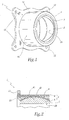
- FIGs 1 and 2 there is shown a member 1 forming a patella, hereinafter called "the patella 1".
- the ball 1 consists of an inner nut 2 and a outer shell 4.
- the inner nut 2 is a metal piece of a alone. This nut has an outer surface 2A whose truncated spherical profile corresponds to that of the inner surface 4B of the outer shell 4, so that the inner nut and the outer shell possess, relative to each other, three degrees of freedom in rotation.
- the inner nut 2 also has a surface substantially cylindrical interior 2B adapted to be mounted on a tubular member, such as a connecting rod.
- the outer shell 4 is made of a material composite including a plastic matrix thermosetting or thermoplastic, such as a resin epoxide, polyamide or phenolic.
- a plastic matrix thermosetting or thermoplastic such as a resin epoxide, polyamide or phenolic.
- this matrix is reinforced with carbon fibers, including so-called long fibers, that is to say having an average length is greater than the thickness of the shell 4.
- the length average fiber is for example between a few millimeters and several meters.
- the plastic matrix is mixed with a fibrous filling self-lubricating 9, that is to say allowing contact sliding with the outer surface 2A of the nut 2 without supply of lubricant.
- This self-lubricating lining includes in particular anti-friction fibers made of polytetrafluoroethylene (PTFE), as well as stiffer fibers within to withstand the contact pressures exerted functioning between the nut and the shell, for example, carbon, aramid and / or glass fibers.
- PTFE polytetrafluoroethylene
- the outer shell 4 has a surface 4A substantially cylindrical outer.
- a flange 10 protrudes from one end of this surface 4A.
- the flange 10 came from matter with the part outer shell 6 and is adapted to allow fixing the shell to a non-structural part represented.
- the flange 10 is provided fastening ears 12.
- a ring metal 14 for forming the inner nut 2 for forming the inner nut 2.
- the geometry and the dimensions of the ring 14 are exactly those of the nut 2.
- This ring is obtained by any known method, by example by machining possibly followed by a grinding and a surface treatment.
- pre-form 16 of the shell 4 that is to say a fibrous skeleton whose shape corresponds substantially to that of the shell 4 to obtain later by molding as explained below.
- the assembly thus formed is placed in a mold waterproof, for example of the type described in the patent FR-B-2 769 866 in which synthetic resin is injected into the pre-form so as to mold the shell exterior 4 of composite material. Injection is planned so that the resin mixes with both the fibrous preform 16 and to the self-lubricating fibrous lining 9 so as to what this filling forms, once the molding is finished, a composite structure constituting an integral part of the shell 4.
- the ring 14, that is to say the nut interior 2 thus forms a counter-molding part of the outer shell 4.
- the resin is injected so as to also form the flange 10.
- the inner nut 2 of the patella 1 thus obtained is indestructible, the outer shell of composite material 4 being reported directly to this nut in imprisoning.
- the resulting patella also has the advantage to integrate in the material of the outer shell 4 the self-lubricating lining, avoiding the use of bonding materials generally weakened during shocks or by the propagation of thermal or sound vibrations.
- the synthetic matrix of the outer shell 4 being mixed with the fiber of this filling, the problems related to differential dilations between the outer part 6 and the inner part 8 of the shell are clearly reduced.
- the flange 10 is in one piece with the rest of the shell 4, without any discontinuity fibers.
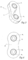
- FIG 5 a member 20 forming two ball joints, variant according to the invention of the ball 1 of Figures 1 and 2.
- This member 20 or “assembly rotulant” comprises two inner nuts 22 1 and 22 2 metal, substantially similar to the nut 2 of the ball 1 and a single composite outer shell 24, substantially similar to the shell 4.
- the respective truncated spherical contact surfaces of each nut 22 1 , 22 2 and each surrounding part of the shell 24 cooperate to form two ball joints whose nuts are indémontables vis-à-vis the shell.
- the organ 20 thus differs essentially from the ball 1 by the shape of its outer shell 24 which is especially adapted to its environment of use higher.
- this body constitutes a attachment of a two-axis accessory, in the field aeronautics.
- two metal rings 26 1 and 26 2 are provided for respectively forming the nuts 22 1 and 22 2 , as well as a single fibrous preform 28 similar in nature to the pre-form 16.
- the pre-form 28 is cut so that its external geometry corresponds substantially to that of the shell 24 to obtain and that it can be reported around the rings 26 1 and 26 2 .
- a corresponding cutting pattern can be used.
- a self-lubricating fibrous liner 30 1 , 30 2 is interposed between each ring and the preform.
- these linings 30 1 and 2 are woven with the corresponding zones of the preform, before the latter is attached around the rings.
- Resin is then injected into the preform so both to obtain the composite structure of the shell 24 and to penetrate the self-lubricating gaskets 30 1 , 2 to firmly bond to the shell.
- the rings 22 1 and 22 2 thus form molding counterparts for the shell 24.
Landscapes
- Engineering & Computer Science (AREA)
- General Engineering & Computer Science (AREA)
- Mechanical Engineering (AREA)
- Injection Moulding Of Plastics Or The Like (AREA)
- Pivots And Pivotal Connections (AREA)
- Prostheses (AREA)
- Orthopedics, Nursing, And Contraception (AREA)
Applications Claiming Priority (2)
| Application Number | Priority Date | Filing Date | Title |
|---|---|---|---|
| FR0313048 | 2003-11-06 | ||
| FR0313048A FR2862112B1 (fr) | 2003-11-06 | 2003-11-06 | Procede de fabrication d'un organe formant au moins une rotule et organe ainsi realise |
Publications (3)
| Publication Number | Publication Date |
|---|---|
| EP1529972A2 true EP1529972A2 (de) | 2005-05-11 |
| EP1529972A3 EP1529972A3 (de) | 2006-05-17 |
| EP1529972B1 EP1529972B1 (de) | 2008-04-16 |
Family
ID=34429950
Family Applications (1)
| Application Number | Title | Priority Date | Filing Date |
|---|---|---|---|
| EP04356177A Expired - Lifetime EP1529972B1 (de) | 2003-11-06 | 2004-11-05 | Herstellungsverfahren eines Bauteils das ein Kugelgelenk bildet und damit hergestelltes Bauteil |
Country Status (4)
| Country | Link |
|---|---|
| EP (1) | EP1529972B1 (de) |
| DE (1) | DE602004013106T2 (de) |
| ES (1) | ES2305698T3 (de) |
| FR (1) | FR2862112B1 (de) |
Families Citing this family (22)
| Publication number | Priority date | Publication date | Assignee | Title |
|---|---|---|---|---|
| DE102012013534B3 (de) | 2012-07-05 | 2013-09-19 | Tobias Sokolowski | Vorrichtung für repetitive Nervenstimulation zum Abbau von Fettgewebe mittels induktiver Magnetfelder |
| US11491342B2 (en) | 2015-07-01 | 2022-11-08 | Btl Medical Solutions A.S. | Magnetic stimulation methods and devices for therapeutic treatments |
| US11266850B2 (en) | 2015-07-01 | 2022-03-08 | Btl Healthcare Technologies A.S. | High power time varying magnetic field therapy |
| US20180001107A1 (en) | 2016-07-01 | 2018-01-04 | Btl Holdings Limited | Aesthetic method of biological structure treatment by magnetic field |
| US10695575B1 (en) | 2016-05-10 | 2020-06-30 | Btl Medical Technologies S.R.O. | Aesthetic method of biological structure treatment by magnetic field |
| US11253717B2 (en) | 2015-10-29 | 2022-02-22 | Btl Healthcare Technologies A.S. | Aesthetic method of biological structure treatment by magnetic field |
| US11247039B2 (en) | 2016-05-03 | 2022-02-15 | Btl Healthcare Technologies A.S. | Device including RF source of energy and vacuum system |
| US11464993B2 (en) | 2016-05-03 | 2022-10-11 | Btl Healthcare Technologies A.S. | Device including RF source of energy and vacuum system |
| US11534619B2 (en) | 2016-05-10 | 2022-12-27 | Btl Medical Solutions A.S. | Aesthetic method of biological structure treatment by magnetic field |
| US10583287B2 (en) | 2016-05-23 | 2020-03-10 | Btl Medical Technologies S.R.O. | Systems and methods for tissue treatment |
| US10556122B1 (en) | 2016-07-01 | 2020-02-11 | Btl Medical Technologies S.R.O. | Aesthetic method of biological structure treatment by magnetic field |
| US11141219B1 (en) | 2016-08-16 | 2021-10-12 | BTL Healthcare Technologies, a.s. | Self-operating belt |
| DE102018131957A1 (de) | 2018-12-12 | 2020-06-18 | Krones Aktiengesellschaft | Gelenk und Verfahren zur Herstellung eines spielarmen oder spielfreien Kugelgelenkes |
| US12156689B2 (en) | 2019-04-11 | 2024-12-03 | Btl Medical Solutions A.S. | Methods and devices for aesthetic treatment of biological structures by radiofrequency and magnetic energy |
| US12558146B2 (en) | 2019-04-11 | 2026-02-24 | Btl Medical Solutions A.S. | Methods and devices for aesthetic treatment of biological structures by radiofrequency and magnetic energy |
| PL4417249T3 (pl) | 2019-04-11 | 2026-04-20 | Btl Medical Solutions A.S. | Urządzenia do zabiegów na strukturach biologicznych za pomocą częstotliwości radiowej |
| US12611545B2 (en) | 2020-05-04 | 2026-04-28 | Btl Healthcare Technologies A.S. | Device and method for unattended treatment of a patient |
| ES2993637T3 (en) | 2020-05-04 | 2025-01-03 | Btl Healthcare Technologies As | Device for unattended treatment of a patient |
| US11878167B2 (en) | 2020-05-04 | 2024-01-23 | Btl Healthcare Technologies A.S. | Device and method for unattended treatment of a patient |
| CA3260012A1 (en) | 2021-10-13 | 2023-04-20 | Btl Medical Solutions A.S. | AESTHETIC TREATMENT DEVICES FOR BIOLOGICAL STRUCTURES USING RADIOFREQUENCY AND MAGNETIC ENERGY |
| US11896816B2 (en) | 2021-11-03 | 2024-02-13 | Btl Healthcare Technologies A.S. | Device and method for unattended treatment of a patient |
| US20260097227A1 (en) | 2024-10-08 | 2026-04-09 | Btl Medical Solutions A.S. | Devices and methods for application of a magnetic field to the nervous system |
Citations (7)
| Publication number | Priority date | Publication date | Assignee | Title |
|---|---|---|---|---|
| US3082485A (en) | 1958-04-07 | 1963-03-26 | American Metal Prod | Elements having low friction material compacted on teh face thereof |
| FR1429483A (fr) | 1964-02-24 | 1966-02-25 | Corps composite destiné à la fabrication d'éléments de paliers | |
| US3700295A (en) | 1971-12-03 | 1972-10-24 | Rex Chainbelt Inc | Ball and socket bearing |
| GB1295258A (de) | 1969-12-01 | 1972-11-08 | ||
| US4111499A (en) | 1975-03-31 | 1978-09-05 | The Heim Universal Corporation | Bearing assembly and liner |
| US5407288A (en) | 1992-06-30 | 1995-04-18 | Tokai Rubber Industries, Ltd. | Sliding type coupling device having slidable member with gap-filling portion and method of producing the same |
| FR2770597A1 (fr) | 1997-10-31 | 1999-05-07 | Sarma | Procede de fabrication d'une bague interieure d'une rotule metallique, et rotule ainsi realisee |
Family Cites Families (1)
| Publication number | Priority date | Publication date | Assignee | Title |
|---|---|---|---|---|
| FR2769866B1 (fr) * | 1997-10-20 | 2000-01-14 | Sarma | Procede de moulage, moule de fabrication d'une piece globalement cylindrique a profil creux en matiere composite et piece obtenue grace a ce procede |
-
2003
- 2003-11-06 FR FR0313048A patent/FR2862112B1/fr not_active Expired - Fee Related
-
2004
- 2004-11-05 ES ES04356177T patent/ES2305698T3/es not_active Expired - Lifetime
- 2004-11-05 EP EP04356177A patent/EP1529972B1/de not_active Expired - Lifetime
- 2004-11-05 DE DE602004013106T patent/DE602004013106T2/de not_active Expired - Lifetime
Patent Citations (7)
| Publication number | Priority date | Publication date | Assignee | Title |
|---|---|---|---|---|
| US3082485A (en) | 1958-04-07 | 1963-03-26 | American Metal Prod | Elements having low friction material compacted on teh face thereof |
| FR1429483A (fr) | 1964-02-24 | 1966-02-25 | Corps composite destiné à la fabrication d'éléments de paliers | |
| GB1295258A (de) | 1969-12-01 | 1972-11-08 | ||
| US3700295A (en) | 1971-12-03 | 1972-10-24 | Rex Chainbelt Inc | Ball and socket bearing |
| US4111499A (en) | 1975-03-31 | 1978-09-05 | The Heim Universal Corporation | Bearing assembly and liner |
| US5407288A (en) | 1992-06-30 | 1995-04-18 | Tokai Rubber Industries, Ltd. | Sliding type coupling device having slidable member with gap-filling portion and method of producing the same |
| FR2770597A1 (fr) | 1997-10-31 | 1999-05-07 | Sarma | Procede de fabrication d'une bague interieure d'une rotule metallique, et rotule ainsi realisee |
Also Published As
| Publication number | Publication date |
|---|---|
| FR2862112A1 (fr) | 2005-05-13 |
| ES2305698T3 (es) | 2008-11-01 |
| FR2862112B1 (fr) | 2007-01-26 |
| DE602004013106D1 (de) | 2008-05-29 |
| EP1529972A3 (de) | 2006-05-17 |
| EP1529972B1 (de) | 2008-04-16 |
| DE602004013106T2 (de) | 2009-07-02 |
Similar Documents
| Publication | Publication Date | Title |
|---|---|---|
| EP1529972B1 (de) | Herstellungsverfahren eines Bauteils das ein Kugelgelenk bildet und damit hergestelltes Bauteil | |
| EP4077883B1 (de) | Schaufel aus verbundwerkstoff mit befestigter eintrittskante mit variabler dichte | |
| EP0761978B1 (de) | Rotor aus thermostrukturellem Verbundmaterial, insbesondere mit grossem Diameter und sein Herstellungsverfahren | |
| CA2892823C (fr) | Procede de fabrication d'un pied d'aube de turbomachine en materiau composite et pied d'aube obtenu par un tel procede | |
| EP2011619B1 (de) | Mechanische Gelenkeinheit, wie beispielsweise eine verdrehbare Einheit, sowie Herstellungsverfahren einer solchen verdrehbaren Einheit | |
| EP2077183B1 (de) | Verbundflansch mit Verarbeitungsteil | |
| EP0677671A1 (de) | Einheit mit einem Schrägkugellager und ihre Anwendung in einer Lenkungsanlage eines Fahrzeuges | |
| EP2946033B1 (de) | Faserstruktur für eine aus einem verbundwerkstoff hergestellte achsensymmetrische komponente mit sich progressiv änderndem durchmesser und bauteil damit | |
| FR3086018A1 (fr) | Dispositif de liaison modulaire verrouillable | |
| FR3146327A1 (fr) | Ensemble comportant une aube et un systeme de calage angulaire de l'aube | |
| JP5371335B2 (ja) | 両面反射鏡及びその製造方法 | |
| EP0913595B1 (de) | Herstellungsverfahren eines Innenringes von einem metallischen Kugelgelenk und so erhaltenes Kugelgelenk | |
| EP3152027A1 (de) | Verfahren zur herstellung eines zahnrades mit verstärkungsreifen | |
| EP1798429B1 (de) | Rohrförmige Pleuelstange aus einem Verbundmaterial und ein entsprechendes Herstellungsverfahren | |
| FR2956710A1 (fr) | Garniture de friction a sec, en particulier pour un embrayage de vehicule automobile | |
| EP0477074A1 (de) | Teleskopisches Antriebsgelenk und Verfahren zur Herstellung eines Elements mit Gleitspuren, insbesondere für ein solches Gelenk | |
| EP2006555B1 (de) | Welle zur Übertragung von Bewegungen und/oder Drehkräften | |
| WO2025027258A1 (fr) | Aube comprenant une structure en matériau composite et un longeron métallique | |
| FR2970897A1 (fr) | Structure fibreuse formant une bride et une contre-bride | |
| EP0962742A1 (de) | Vorrichtung zum Schneiden von nicht-metallischen Stücken mittels eines pyrotechnischen Ausdehnungsrohres | |
| WO2000045039A1 (fr) | Systeme d'activation de tuyere orientable pour propulseur a reaction utilisant plusieurs ensembles elastiques repartis circonferentiellement | |
| EP0489608A1 (de) | Eine Verbundstruktur aufweisender Antriebsgelenkkörper | |
| FR3018104A1 (fr) | Procede d'assemblage d'un arbre a cames | |
| FR2784711A1 (fr) | Dispositif de commande d'aubes a angle de calage variable | |
| EP3530633A1 (de) | Keramische wabenstruktur und verfahren zur herstellung davon |
Legal Events
| Date | Code | Title | Description |
|---|---|---|---|
| PUAI | Public reference made under article 153(3) epc to a published international application that has entered the european phase |
Free format text: ORIGINAL CODE: 0009012 |
|
| AK | Designated contracting states |
Kind code of ref document: A2 Designated state(s): AT BE BG CH CY CZ DE DK EE ES FI FR GB GR HU IE IS IT LI LU MC NL PL PT RO SE SI SK TR |
|
| AX | Request for extension of the european patent |
Extension state: AL HR LT LV MK YU |
|
| RIN1 | Information on inventor provided before grant (corrected) |
Inventor name: MAHEO, YVES |
|
| PUAL | Search report despatched |
Free format text: ORIGINAL CODE: 0009013 |
|
| AK | Designated contracting states |
Kind code of ref document: A3 Designated state(s): AT BE BG CH CY CZ DE DK EE ES FI FR GB GR HU IE IS IT LI LU MC NL PL PT RO SE SI SK TR |
|
| AX | Request for extension of the european patent |
Extension state: AL HR LT LV MK YU |
|
| RAP1 | Party data changed (applicant data changed or rights of an application transferred) |
Owner name: SKF AEROSPACE FRANCE |
|
| 17P | Request for examination filed |
Effective date: 20061016 |
|
| 17Q | First examination report despatched |
Effective date: 20061128 |
|
| AKX | Designation fees paid |
Designated state(s): DE ES FR GB |
|
| GRAP | Despatch of communication of intention to grant a patent |
Free format text: ORIGINAL CODE: EPIDOSNIGR1 |
|
| GRAS | Grant fee paid |
Free format text: ORIGINAL CODE: EPIDOSNIGR3 |
|
| GRAA | (expected) grant |
Free format text: ORIGINAL CODE: 0009210 |
|
| AK | Designated contracting states |
Kind code of ref document: B1 Designated state(s): DE ES FR GB |
|
| REF | Corresponds to: |
Ref document number: 602004013106 Country of ref document: DE Date of ref document: 20080529 Kind code of ref document: P |
|
| REG | Reference to a national code |
Ref country code: ES Ref legal event code: FG2A Ref document number: 2305698 Country of ref document: ES Kind code of ref document: T3 |
|
| PLBE | No opposition filed within time limit |
Free format text: ORIGINAL CODE: 0009261 |
|
| STAA | Information on the status of an ep patent application or granted ep patent |
Free format text: STATUS: NO OPPOSITION FILED WITHIN TIME LIMIT |
|
| 26N | No opposition filed |
Effective date: 20090119 |
|
| REG | Reference to a national code |
Ref country code: FR Ref legal event code: PLFP Year of fee payment: 12 |
|
| REG | Reference to a national code |
Ref country code: FR Ref legal event code: PLFP Year of fee payment: 13 |
|
| REG | Reference to a national code |
Ref country code: FR Ref legal event code: PLFP Year of fee payment: 14 |
|
| P01 | Opt-out of the competence of the unified patent court (upc) registered |
Effective date: 20230606 |
|
| PGFP | Annual fee paid to national office [announced via postgrant information from national office to epo] |
Ref country code: GB Payment date: 20231121 Year of fee payment: 20 |
|
| PGFP | Annual fee paid to national office [announced via postgrant information from national office to epo] |
Ref country code: ES Payment date: 20231218 Year of fee payment: 20 |
|
| PGFP | Annual fee paid to national office [announced via postgrant information from national office to epo] |
Ref country code: FR Payment date: 20231123 Year of fee payment: 20 Ref country code: DE Payment date: 20231127 Year of fee payment: 20 |
|
| REG | Reference to a national code |
Ref country code: DE Ref legal event code: R071 Ref document number: 602004013106 Country of ref document: DE |
|
| REG | Reference to a national code |
Ref country code: ES Ref legal event code: FD2A Effective date: 20241126 |
|
| REG | Reference to a national code |
Ref country code: GB Ref legal event code: PE20 Expiry date: 20241104 |
|
| PG25 | Lapsed in a contracting state [announced via postgrant information from national office to epo] |
Ref country code: GB Free format text: LAPSE BECAUSE OF EXPIRATION OF PROTECTION Effective date: 20241104 |
|
| PG25 | Lapsed in a contracting state [announced via postgrant information from national office to epo] |
Ref country code: ES Free format text: LAPSE BECAUSE OF EXPIRATION OF PROTECTION Effective date: 20241106 |
|
| PG25 | Lapsed in a contracting state [announced via postgrant information from national office to epo] |
Ref country code: GB Free format text: LAPSE BECAUSE OF EXPIRATION OF PROTECTION Effective date: 20241104 Ref country code: ES Free format text: LAPSE BECAUSE OF EXPIRATION OF PROTECTION Effective date: 20241106 |