EP1529925A2 - Verfahren und Vorrichtung zur Vermeidung der Rissausbreitung in einem keramischen Verbundkörper - Google Patents
Verfahren und Vorrichtung zur Vermeidung der Rissausbreitung in einem keramischen Verbundkörper Download PDFInfo
- Publication number
- EP1529925A2 EP1529925A2 EP04256825A EP04256825A EP1529925A2 EP 1529925 A2 EP1529925 A2 EP 1529925A2 EP 04256825 A EP04256825 A EP 04256825A EP 04256825 A EP04256825 A EP 04256825A EP 1529925 A2 EP1529925 A2 EP 1529925A2
- Authority
- EP
- European Patent Office
- Prior art keywords
- crack
- patch
- assembly
- flaps
- wire mesh
- Prior art date
- Legal status (The legal status is an assumption and is not a legal conclusion. Google has not performed a legal analysis and makes no representation as to the accuracy of the status listed.)
- Granted
Links
Images


Classifications
-
- C—CHEMISTRY; METALLURGY
- C04—CEMENTS; CONCRETE; ARTIFICIAL STONE; CERAMICS; REFRACTORIES
- C04B—LIME, MAGNESIA; SLAG; CEMENTS; COMPOSITIONS THEREOF, e.g. MORTARS, CONCRETE OR LIKE BUILDING MATERIALS; ARTIFICIAL STONE; CERAMICS; REFRACTORIES; TREATMENT OF NATURAL STONE
- C04B37/00—Joining burned ceramic articles with other burned ceramic articles or other articles by heating
- C04B37/02—Joining burned ceramic articles with other burned ceramic articles or other articles by heating with metallic articles
- C04B37/023—Joining burned ceramic articles with other burned ceramic articles or other articles by heating with metallic articles characterised by the interlayer used
- C04B37/025—Joining burned ceramic articles with other burned ceramic articles or other articles by heating with metallic articles characterised by the interlayer used consisting of glass or ceramic material
-
- F—MECHANICAL ENGINEERING; LIGHTING; HEATING; WEAPONS; BLASTING
- F02—COMBUSTION ENGINES; HOT-GAS OR COMBUSTION-PRODUCT ENGINE PLANTS
- F02K—JET-PROPULSION PLANTS
- F02K1/00—Plants characterised by the form or arrangement of the jet pipe or nozzle; Jet pipes or nozzles peculiar thereto
- F02K1/06—Varying effective area of jet pipe or nozzle
-
- C—CHEMISTRY; METALLURGY
- C23—COATING METALLIC MATERIAL; COATING MATERIAL WITH METALLIC MATERIAL; CHEMICAL SURFACE TREATMENT; DIFFUSION TREATMENT OF METALLIC MATERIAL; COATING BY VACUUM EVAPORATION, BY SPUTTERING, BY ION IMPLANTATION OR BY CHEMICAL VAPOUR DEPOSITION, IN GENERAL; INHIBITING CORROSION OF METALLIC MATERIAL OR INCRUSTATION IN GENERAL
- C23C—COATING METALLIC MATERIAL; COATING MATERIAL WITH METALLIC MATERIAL; SURFACE TREATMENT OF METALLIC MATERIAL BY DIFFUSION INTO THE SURFACE, BY CHEMICAL CONVERSION OR SUBSTITUTION; COATING BY VACUUM EVAPORATION, BY SPUTTERING, BY ION IMPLANTATION OR BY CHEMICAL VAPOUR DEPOSITION, IN GENERAL
- C23C26/00—Coating not provided for in groups C23C2/00 - C23C24/00
-
- F—MECHANICAL ENGINEERING; LIGHTING; HEATING; WEAPONS; BLASTING
- F01—MACHINES OR ENGINES IN GENERAL; ENGINE PLANTS IN GENERAL; STEAM ENGINES
- F01D—NON-POSITIVE DISPLACEMENT MACHINES OR ENGINES, e.g. STEAM TURBINES
- F01D5/00—Blades; Blade-carrying members; Heating, heat-insulating, cooling or antivibration means on the blades or the members
- F01D5/005—Repairing methods or devices
-
- C—CHEMISTRY; METALLURGY
- C04—CEMENTS; CONCRETE; ARTIFICIAL STONE; CERAMICS; REFRACTORIES
- C04B—LIME, MAGNESIA; SLAG; CEMENTS; COMPOSITIONS THEREOF, e.g. MORTARS, CONCRETE OR LIKE BUILDING MATERIALS; ARTIFICIAL STONE; CERAMICS; REFRACTORIES; TREATMENT OF NATURAL STONE
- C04B2237/00—Aspects relating to ceramic laminates or to joining of ceramic articles with other articles by heating
- C04B2237/02—Aspects relating to interlayers, e.g. used to join ceramic articles with other articles by heating
- C04B2237/04—Ceramic interlayers
- C04B2237/06—Oxidic interlayers
- C04B2237/062—Oxidic interlayers based on silica or silicates
-
- C—CHEMISTRY; METALLURGY
- C04—CEMENTS; CONCRETE; ARTIFICIAL STONE; CERAMICS; REFRACTORIES
- C04B—LIME, MAGNESIA; SLAG; CEMENTS; COMPOSITIONS THEREOF, e.g. MORTARS, CONCRETE OR LIKE BUILDING MATERIALS; ARTIFICIAL STONE; CERAMICS; REFRACTORIES; TREATMENT OF NATURAL STONE
- C04B2237/00—Aspects relating to ceramic laminates or to joining of ceramic articles with other articles by heating
- C04B2237/02—Aspects relating to interlayers, e.g. used to join ceramic articles with other articles by heating
- C04B2237/04—Ceramic interlayers
- C04B2237/06—Oxidic interlayers
- C04B2237/064—Oxidic interlayers based on alumina or aluminates
-
- C—CHEMISTRY; METALLURGY
- C04—CEMENTS; CONCRETE; ARTIFICIAL STONE; CERAMICS; REFRACTORIES
- C04B—LIME, MAGNESIA; SLAG; CEMENTS; COMPOSITIONS THEREOF, e.g. MORTARS, CONCRETE OR LIKE BUILDING MATERIALS; ARTIFICIAL STONE; CERAMICS; REFRACTORIES; TREATMENT OF NATURAL STONE
- C04B2237/00—Aspects relating to ceramic laminates or to joining of ceramic articles with other articles by heating
- C04B2237/02—Aspects relating to interlayers, e.g. used to join ceramic articles with other articles by heating
- C04B2237/10—Glass interlayers, e.g. frit or flux
-
- C—CHEMISTRY; METALLURGY
- C04—CEMENTS; CONCRETE; ARTIFICIAL STONE; CERAMICS; REFRACTORIES
- C04B—LIME, MAGNESIA; SLAG; CEMENTS; COMPOSITIONS THEREOF, e.g. MORTARS, CONCRETE OR LIKE BUILDING MATERIALS; ARTIFICIAL STONE; CERAMICS; REFRACTORIES; TREATMENT OF NATURAL STONE
- C04B2237/00—Aspects relating to ceramic laminates or to joining of ceramic articles with other articles by heating
- C04B2237/30—Composition of layers of ceramic laminates or of ceramic or metallic articles to be joined by heating, e.g. Si substrates
- C04B2237/32—Ceramic
- C04B2237/34—Oxidic
-
- C—CHEMISTRY; METALLURGY
- C04—CEMENTS; CONCRETE; ARTIFICIAL STONE; CERAMICS; REFRACTORIES
- C04B—LIME, MAGNESIA; SLAG; CEMENTS; COMPOSITIONS THEREOF, e.g. MORTARS, CONCRETE OR LIKE BUILDING MATERIALS; ARTIFICIAL STONE; CERAMICS; REFRACTORIES; TREATMENT OF NATURAL STONE
- C04B2237/00—Aspects relating to ceramic laminates or to joining of ceramic articles with other articles by heating
- C04B2237/30—Composition of layers of ceramic laminates or of ceramic or metallic articles to be joined by heating, e.g. Si substrates
- C04B2237/40—Metallic
- C04B2237/405—Iron metal group, e.g. Co or Ni
-
- C—CHEMISTRY; METALLURGY
- C04—CEMENTS; CONCRETE; ARTIFICIAL STONE; CERAMICS; REFRACTORIES
- C04B—LIME, MAGNESIA; SLAG; CEMENTS; COMPOSITIONS THEREOF, e.g. MORTARS, CONCRETE OR LIKE BUILDING MATERIALS; ARTIFICIAL STONE; CERAMICS; REFRACTORIES; TREATMENT OF NATURAL STONE
- C04B2237/00—Aspects relating to ceramic laminates or to joining of ceramic articles with other articles by heating
- C04B2237/50—Processing aspects relating to ceramic laminates or to the joining of ceramic articles with other articles by heating
- C04B2237/52—Pre-treatment of the joining surfaces, e.g. cleaning, machining
-
- C—CHEMISTRY; METALLURGY
- C04—CEMENTS; CONCRETE; ARTIFICIAL STONE; CERAMICS; REFRACTORIES
- C04B—LIME, MAGNESIA; SLAG; CEMENTS; COMPOSITIONS THEREOF, e.g. MORTARS, CONCRETE OR LIKE BUILDING MATERIALS; ARTIFICIAL STONE; CERAMICS; REFRACTORIES; TREATMENT OF NATURAL STONE
- C04B2237/00—Aspects relating to ceramic laminates or to joining of ceramic articles with other articles by heating
- C04B2237/50—Processing aspects relating to ceramic laminates or to the joining of ceramic articles with other articles by heating
- C04B2237/62—Forming laminates or joined articles comprising holes, channels or other types of openings
-
- C—CHEMISTRY; METALLURGY
- C04—CEMENTS; CONCRETE; ARTIFICIAL STONE; CERAMICS; REFRACTORIES
- C04B—LIME, MAGNESIA; SLAG; CEMENTS; COMPOSITIONS THEREOF, e.g. MORTARS, CONCRETE OR LIKE BUILDING MATERIALS; ARTIFICIAL STONE; CERAMICS; REFRACTORIES; TREATMENT OF NATURAL STONE
- C04B2237/00—Aspects relating to ceramic laminates or to joining of ceramic articles with other articles by heating
- C04B2237/50—Processing aspects relating to ceramic laminates or to the joining of ceramic articles with other articles by heating
- C04B2237/86—Joining of two substrates at their largest surfaces, one surface being complete joined and covered, the other surface not, e.g. a small plate joined at it's largest surface on top of a larger plate
-
- F—MECHANICAL ENGINEERING; LIGHTING; HEATING; WEAPONS; BLASTING
- F05—INDEXING SCHEMES RELATING TO ENGINES OR PUMPS IN VARIOUS SUBCLASSES OF CLASSES F01-F04
- F05D—INDEXING SCHEME FOR ASPECTS RELATING TO NON-POSITIVE-DISPLACEMENT MACHINES OR ENGINES, GAS-TURBINES OR JET-PROPULSION PLANTS
- F05D2230/00—Manufacture
- F05D2230/80—Repairing, retrofitting or upgrading methods
-
- Y—GENERAL TAGGING OF NEW TECHNOLOGICAL DEVELOPMENTS; GENERAL TAGGING OF CROSS-SECTIONAL TECHNOLOGIES SPANNING OVER SEVERAL SECTIONS OF THE IPC; TECHNICAL SUBJECTS COVERED BY FORMER USPC CROSS-REFERENCE ART COLLECTIONS [XRACs] AND DIGESTS
- Y10—TECHNICAL SUBJECTS COVERED BY FORMER USPC
- Y10T—TECHNICAL SUBJECTS COVERED BY FORMER US CLASSIFICATION
- Y10T29/00—Metal working
- Y10T29/49—Method of mechanical manufacture
- Y10T29/49316—Impeller making
- Y10T29/49318—Repairing or disassembling
-
- Y—GENERAL TAGGING OF NEW TECHNOLOGICAL DEVELOPMENTS; GENERAL TAGGING OF CROSS-SECTIONAL TECHNOLOGIES SPANNING OVER SEVERAL SECTIONS OF THE IPC; TECHNICAL SUBJECTS COVERED BY FORMER USPC CROSS-REFERENCE ART COLLECTIONS [XRACs] AND DIGESTS
- Y10—TECHNICAL SUBJECTS COVERED BY FORMER USPC
- Y10T—TECHNICAL SUBJECTS COVERED BY FORMER US CLASSIFICATION
- Y10T428/00—Stock material or miscellaneous articles
- Y10T428/20—Patched hole or depression
Definitions
- the present invention relates generally to ceramic matrix composite materials, and more specifically to a method and apparatus for arresting cracks within ceramic matrix composite materials.
- Gas turbine engines typically include a compressor, a combustor, and a turbine. Airflow entering the compressor is compressed and channeled to the combustor, wherein the air is mixed with a fuel and ignited within a combustion chamber to produce combustion gases. The combustion gases are channeled to a turbine that extracts energy from the combustion gases for powering the compressor. One turbine extracts energy from the combustion gases to power the compressor. Other turbines may be used to power an output shaft connected to a load, such as an electrical generator. In some applications, the combustion gases exiting the turbine(s) are channeled through an engine exhaust nozzle to produce thrust for propelling an aircraft in flight.
- Some known gas turbine aircraft engines include an engine exhaust nozzle having a variable geometry configuration, wherein a cross-sectional area of the exhaust nozzle is adjustable.
- Variable geometry exhaust nozzles typically have a plurality of flaps and a plurality of seals mounted circumferentially about a centerline of the exhaust nozzle. The seals are mounted generally between adjacent nozzle flaps, such that the flaps and seals form a generally continuous interior surface that directs a flow of the combustion gases through the exhaust nozzle.
- the seals seal the spaces between the flaps and shield various components of the exhaust nozzle from high temperatures and high thermal gradients during flow of the combustion gases therein.
- some seals are fabricated from non-metallic composite materials, such as ceramic matrix composite materials.
- non-metallic composite materials such as ceramic matrix composite materials.
- non-metallic materials experience wear and other damage due to the hostile operating environment in gas turbine engines.
- cracks may develop within the seals because of the high thermal gradients the seals experience during operation.
- Known methods for repairing such cracks typically include replacement of the seal with an undamaged seal, or replacement of a portion of the seal with undamaged material.
- replacement of a seal or a portion thereof can be costly and may result in disposal of seals still having a useful operational life.
- an inseparable assembly including a body having a first surface and a second surface.
- the body includes an oxide-based ceramic matrix composite material having a first predetermined ductility.
- the assembly further includes a crack extending through the body between the first surface and the second surface, and a patch bonded to at least one of the first surface and the second surface overlapping at least a portion of an edge of the crack.
- the patch includes a second material having a second predetermined ductility that is greater than the first ductility.
- a variable geometry exhaust nozzle for a gas turbine engine having an exhaust centerline.
- the nozzle includes a plurality of flaps arranged around the exhaust centerline, wherein each of the flaps has a sealing surface, and a plurality of flap seals.
- Each of the seals has a body which includes a sealing surface. The body is positioned between a pair of flaps of the plurality of flaps so that the sealing surface of the seal engages the sealing surface of at least one of the adjacent flaps.
- At least one of the seals has a crack extending through the seal to the sealing surface of the seal. At least a portion of the crack is overlapped by a patch comprising a metallic wire mesh bonded to the body with an adhesive.
- a method for arresting a crack within a body having a first surface and a second surface.
- the body includes an oxide-based ceramic matrix composite material.
- the crack extends through the body between the first surface and the second surface.
- the method includes the steps of positioning a patch which includes a metallic wire mesh over at least one of the first surface and the second surface so the patch overlaps at least a portion of an edge of the crack, and bonding the positioned metallic wire mesh to the surface of the body.
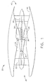
- Fig. 1 is a schematic of a gas turbine engine 20 including a fan 22, a high pressure compressor 24, and a combustor 26.
- the engine 20 also includes a high pressure turbine 28 and a low pressure turbine 30.
- the fan 22 and the turbine 30 are coupled by a first shaft 34, and the high pressure compressor 24 and the turbine 28 are coupled by a second shaft 36.
- the engine 20 is a F414 engine commercially available from GE Aircraft Engines, Evendale, Ohio.
- air received through an inlet end 38 of the engine 20 is compressed by the fan 22 and channeled to the high pressure compressor 24, wherein the compressed air is compressed even further.
- the highly compressed air from the high pressure compressor 22 is channeled to the combustor 26, wherein it is mixed with a fuel and ignited to produce combustion gases.
- the combustion gases are channeled from the combustor 26 to drive the turbines 28 and 30, and exit an outlet end 40 of the engine 20 through an exhaust nozzle assembly 42 to provide thrust.
- Fig. 2 is a perspective of a portion of the gas turbine engine 20 illustrating a sector of the exhaust nozzle assembly 42.
- Fig. 3 is a cross section of the exhaust nozzle assembly 42 taken along line 3-3 of Fig. 2.
- the nozzle assembly 42 includes a plurality of flaps 70 and a plurality of flap seals 72.
- the flaps 70 and the flap seals 72 are arranged circumferentially around a centerline 74 of the exhaust nozzle assembly 42.
- Each flap seal 72 is positioned between a pair of adjacent flaps 70 and radially inwardly with respect to the flaps 70, such that a portion of each flap seal 72 overlaps a portion of each adjacent flap 70.
- each flap 70 includes a body 76 having a sealing surface 78
- each flap seal 72 includes a body, generally referred to by the reference numeral 80, having a sealing surface 82.
- the flap seals 72 overlap adjacent flaps 70 such that during operation of the engine 20 a portion of each flap sealing surface 78 contacts a portion of each corresponding sealing surface 82 generally along an axial length of the flaps 70 and the flap seals 72.
- the flap seal bodies 80 are fabricated from a ceramic matrix composite material.
- the flap seal bodies 80 are fabricated from an oxide-based ceramic matrix composite material.
- the flap bodies 76 are fabricated from a ceramic matrix composite material.
- Respective radially inner surfaces 86 and 88 of the flaps 70 and the flap seals 72 form a generally continuous interior surface defining an exhaust nozzle orifice 90.
- the orifice 90 directs a flowpath of gases received from the turbine 30 (shown in Fig. 1) out of the engine outlet end 40 to produce thrust.
- the exhaust nozzle assembly 42 is a variable geometry exhaust nozzle, wherein a cross-sectional area of the nozzle orifice 90 is adjustable.
- a mounting assembly generally referred to herein with the reference numeral 92, couples each flap seal 72 to adjacent flaps 70.
- the assembly 92 is movably coupled to an outer casing 94 of the engine 20 to facilitate adjustment of the cross-sectional area of the orifice 90.
- the assembly 92 allows relative motion between the flaps 70 and the flap seals 72 to facilitate contact between the sealing surfaces 78 and respective sealing surfaces 82, and to facilitate adjustment of the cross-sectional area of the orifice 90.
- the exhaust nozzle orifice 90 is generally annular, however, it should be understood the orifice 90 may be any suitable shape.
- the exhaust nozzle orifice 90 is generally rectangular.
- a pressure of the flowpath gases exiting through the exhaust nozzle orifice 90 urges the flap seals 72 against the flaps 70, and more specifically, urges the sealing surfaces 82 of the seals 72 in contact with respective sealing surfaces 78 of the flaps 70.
- contact between the sealing surfaces 78 and respective sealing surfaces 82 substantially prevents leakage of gases between the flaps 70 and the flap seals 72.
- Fig. 4 is a perspective of an exemplary flap seal body 80 for use with the exhaust nozzle assembly 42 (shown in Figure 2).
- the body 80 includes the sealing surface 82 and the radially inner surface 88.
- the body 80 includes other surfaces 120, 122, 124, and 126. Any of the surfaces 82, 88, 120, 122, 124, and 126 may be designated a first surface or a second surface.
- the body 80 also includes a crack, generally referred to by the reference numeral 128, extending therethrough from one surface (e.g., surface 82) to another surface (e.g., surface 88), and a plurality of openings, generally referred to by the reference numeral 130, for attachment to the mounting assembly 92 (shown in Figure 3).
- the crack 128 extends between edges 132, 134, and 136 corresponding to surfaces 122, 82, and 88 of the body 80.
- the crack 128 extends completely through the body 80 from the sealing surface 82 to the radially inner surface 88.
- the crack 128 may extend anywhere within the body 80 such that the crack 128 extends between (and not necessarily to) any surfaces of the body 80.
- the crack 128 may adversely affect the performance and useful life of the flap seal 72. More specifically, the crack 128 may increase a permeability of the body 80, which may result in leakage of gases through the body 80 thereby decreasing an efficiency of the engine 20. Additionally, the crack 128 may facilitate failure of the flap seal 72.
- Fig. 5 is a perspective view of the flap seal body 80 including an exemplary patch, generally referred to by the reference numeral 150, bonded thereto to prevent, also referred to herein as arrest, the crack 128 from propagating further through the body 80.
- the patch 150 is bonded to the sealing surface 82.
- the seal body 80 includes a plurality of the patches 150 bonded thereto.
- the patch 150 has a predetermined ductility that is greater than a predetermined ductility of a portion of the flap seal body 80 adjacent the crack 128.
- the flap seal body 80 has a substantially uniform ductility throughout that is less than the predetermined ductility of the patch 150.
- the patch 150 is bonded to the body 80 such that the patch 150 overlaps a portion of the crack edge 134.
- the patch 150 may be bonded to the body 80 in any suitable position that facilitates arresting the crack 128, and more specifically, such that the patch 150 overlaps at least a portion of any edge of the crack 128.
- the patch 150 is bonded to the seal body 80 using an adhesive.
- the adhesive used to bond the patch 150 to the seal body 80 is a ceramic adhesive, for example, a ceramic adhesive produced by combining a glass powder, for example, SP921® glass powder from Specialty Glass, Florida, and an alumina powder with a silica yielding polymer.
- the patch 150 is a metallic wire mesh, however, it should be understood that the patch 150 may be any material, and may be fabricated in any material configuration, having a ductility greater than a predetermined ductility of a portion of the flap seal body 80 that is adjacent the crack 128.
- the patch 150 is a metallic wire mesh fabricated from a nickel-based alloy, such as, for example, HAYNES® HASTELLOY XTM alloy, commercially available from Haynes International, Inc., Kokomo, Indiana.
- the patch 150 is a metallic wire mesh fabricated from a cobalt-based alloy, such as, for example, HAYNES® alloy 230, commercially available from Haynes International, Inc., Kokomo, Indiana.
- the patch 150 is a metallic wire mesh fabricated from stainless steel, such as, for example, stainless steel grade 316 commercially available from Cleveland Wire Cloth, Cleveland, Ohio.
- the sealing surface 82 Prior to bonding the patch 150 to the flap seal body 80, the sealing surface 82 is cleaned by slightly sanding the surface and applying a solvent, for example acetone or isopropanol, to provide a substantially wetable surface that facilitates adhesion between the adhesive and the sealing surface 82. After cleaning, the adhesive is applied to the patch 150 and the sealing surface 82. The patch 150 is then positioned on the sealing surface 82 over the crack 128 such that the patch 150 overlaps a portion of the crack edge 134, as illustrated in Figure 5. Once dry, the adhesive bonds the patch 150 to the sealing surface 82. The greater ductility of the patch 150 with respect to the body 80 prevents the crack 128 from propagating through the body 80 by reinforcing the body 80 adjacent a portion of the crack edge 134.
- a solvent for example acetone or isopropanol
- the above-described patch is cost-effective and reliable for arresting the propagation of a crack through a ceramic matrix composite material. More specifically, the patch facilitates reinforcing a portion of the ceramic matrix composite material that is adjacent the crack. As a result, the patch may increase the performance and useful life of the ceramic matrix composite material, and thereby reduce replacement costs. Additionally, the patch may increase a wear resistance and a strain to failure ratio of the ceramic matrix composite material, and may allow the ceramic matrix composite material to experience higher thermal gradients without failing. In the exemplary embodiment, the patch facilitates increasing the performance and useful life of a gas turbine engine exhaust seal having a crack therein. As a result, the exemplary patch facilitates maintaining a desired operational efficiency of the gas turbine engine without replacing cracked exhaust seals within the engine.
- gas turbine engine exhaust nozzle assemblies are described above in detail.
- the assemblies are not limited to the specific embodiments described herein, but rather, components of each assembly may be utilized independently and separately from other components described herein.
- Each exhaust nozzle assembly component can also be used in combination with other exhaust nozzle assembly components.
Landscapes
- Engineering & Computer Science (AREA)
- Chemical & Material Sciences (AREA)
- Mechanical Engineering (AREA)
- Materials Engineering (AREA)
- General Engineering & Computer Science (AREA)
- Organic Chemistry (AREA)
- Ceramic Engineering (AREA)
- Chemical Kinetics & Catalysis (AREA)
- Combustion & Propulsion (AREA)
- Metallurgy (AREA)
- Structural Engineering (AREA)
- Turbine Rotor Nozzle Sealing (AREA)
- Laminated Bodies (AREA)
- Ceramic Products (AREA)
- Gasket Seals (AREA)
Applications Claiming Priority (2)
| Application Number | Priority Date | Filing Date | Title |
|---|---|---|---|
| US703274 | 2003-11-07 | ||
| US10/703,274 US7310949B2 (en) | 2003-11-07 | 2003-11-07 | Method and apparatus for arresting a crack within a body |
Publications (3)
| Publication Number | Publication Date |
|---|---|
| EP1529925A2 true EP1529925A2 (de) | 2005-05-11 |
| EP1529925A3 EP1529925A3 (de) | 2012-11-21 |
| EP1529925B1 EP1529925B1 (de) | 2016-08-24 |
Family
ID=34435569
Family Applications (1)
| Application Number | Title | Priority Date | Filing Date |
|---|---|---|---|
| EP04256825.3A Expired - Lifetime EP1529925B1 (de) | 2003-11-07 | 2004-11-04 | Verfahren zur Vermeidung der Rissausbreitung in einem keramischen Verbundkörper |
Country Status (4)
| Country | Link |
|---|---|
| US (1) | US7310949B2 (de) |
| EP (1) | EP1529925B1 (de) |
| JP (1) | JP4596389B2 (de) |
| CA (1) | CA2486237C (de) |
Families Citing this family (11)
| Publication number | Priority date | Publication date | Assignee | Title |
|---|---|---|---|---|
| US20050097893A1 (en) * | 2003-11-07 | 2005-05-12 | General Electric Company | Method and apparatus for increasing a durability of a body |
| FR2873757B1 (fr) * | 2004-07-28 | 2006-09-29 | Snecma Moteurs Sa | Tuyere convergente de turboreacteur |
| EP1857218A1 (de) * | 2006-05-18 | 2007-11-21 | Siemens Aktiengesellschaft | Verfahren zur Reparatur eines Bauteils und ein Bauteil |
| FR2925572B1 (fr) * | 2007-12-24 | 2010-02-12 | Snecma Services | Procede de choix d'un arrangement de secteurs pour un distributeur pour turbomachine |
| US8122722B2 (en) * | 2008-02-29 | 2012-02-28 | General Electric Company | Exhaust nozzle seal with segmented basesheet disposed between side rails |
| US8359868B2 (en) * | 2008-09-11 | 2013-01-29 | General Electric Company | Low BTU fuel flow ratio duct burner for heating and heat recovery systems |
| US8202056B2 (en) * | 2008-10-16 | 2012-06-19 | Rolls-Royce Corporation | Morphable composite structure |
| US20100098896A1 (en) * | 2008-10-16 | 2010-04-22 | Edward Claude Rice | Patch |
| US8778487B2 (en) * | 2008-10-16 | 2014-07-15 | Rolls-Royce Corporation | Tape |
| US9664052B2 (en) | 2012-10-03 | 2017-05-30 | General Electric Company | Turbine component, turbine blade, and turbine component fabrication process |
| US11097384B2 (en) * | 2019-01-23 | 2021-08-24 | General Electric Company | Mechanical ceramic matrix composite (CMS) repair |
Family Cites Families (21)
| Publication number | Priority date | Publication date | Assignee | Title |
|---|---|---|---|---|
| US4780432A (en) * | 1986-09-02 | 1988-10-25 | United Technologies Corporation | Controlled fiber distribution technique for glass matrix composites |
| US4837230A (en) * | 1987-05-07 | 1989-06-06 | Kaiser Aerotech | Structural ceramic materials having refractory interface layers |
| US4916092A (en) * | 1988-02-04 | 1990-04-10 | Martin Marietta Energy Systems, Inc. | Ceramic composites reinforced with modified silicon carbide whiskers |
| US4994416A (en) * | 1988-02-04 | 1991-02-19 | Martin Marietta Energy Systems, Inc. | Ceramic composites reinforced with modified silicon carbide whiskers and method for modifying the whiskers |
| US5137852A (en) * | 1991-01-11 | 1992-08-11 | Rockwell International Corp. | High temperature ceramic composites |
| US6338906B1 (en) * | 1992-09-17 | 2002-01-15 | Coorstek, Inc. | Metal-infiltrated ceramic seal |
| IL109085A (en) * | 1993-04-05 | 1997-08-14 | Gen Electric | Nozzle seal assembly with removable baseplate |
| CA2137528C (en) * | 1994-04-15 | 2001-07-03 | Peter E. D. Morgan | Ceramic composites having a weak bond interphase material selected from monazites and xenotimes |
| CA2181497C (en) * | 1996-07-18 | 2002-04-09 | Fernand Ellyin | Carbon fiber-reinforced polymer patch for defect repair of a structural steel component |
| US5839663A (en) * | 1996-07-23 | 1998-11-24 | United Technologies Corporation | Gas turbine exhaust nozzle flap and flap seal apparatus |
| JP3629920B2 (ja) * | 1997-10-20 | 2005-03-16 | 株式会社日立製作所 | ガスタービン用ノズル,発電用ガスタービン,Co基合金及び溶接材料 |
| US6156142A (en) * | 1998-10-13 | 2000-12-05 | Owens Corning Fiberglas Technology, Inc. | Method for repairing consumable polymer-modified asphalt containers |
| US6210108B1 (en) * | 1999-08-16 | 2001-04-03 | General Electric Company | Method for making an article portion subject to tensile stress and stress relieved article |
| US6240720B1 (en) * | 1999-09-09 | 2001-06-05 | General Electric Company | Hybrid-composite gas turbine exhaust nozzle compression link |
| US6471469B2 (en) * | 2000-11-30 | 2002-10-29 | General Electric Company | Methods and apparatus for sealing gas turbine engine variable nozzles |
| FR2827308B1 (fr) * | 2001-07-12 | 2004-05-14 | Snecma Moteurs | Procede de reparation globale d'une piece revetue d'une barriere thermique |
| US6820334B2 (en) * | 2002-04-19 | 2004-11-23 | General Electric Company | Method for repairing articles of ceramic composites |
| US7146725B2 (en) * | 2003-05-06 | 2006-12-12 | Siemens Power Generation, Inc. | Repair of combustion turbine components |
| US7028462B2 (en) * | 2003-11-07 | 2006-04-18 | General Electric Company | Method and apparatus for arresting a crack within a body |
| JP4504660B2 (ja) * | 2003-11-13 | 2010-07-14 | 日本碍子株式会社 | セラミックハニカム構造体 |
| US20060234579A1 (en) * | 2005-04-14 | 2006-10-19 | Adam Steven J | High temperature ceramic-based thermal protection material |
-
2003
- 2003-11-07 US US10/703,274 patent/US7310949B2/en not_active Expired - Lifetime
-
2004
- 2004-10-28 CA CA2486237A patent/CA2486237C/en not_active Expired - Fee Related
- 2004-11-04 EP EP04256825.3A patent/EP1529925B1/de not_active Expired - Lifetime
- 2004-11-05 JP JP2004321702A patent/JP4596389B2/ja not_active Expired - Fee Related
Also Published As
| Publication number | Publication date |
|---|---|
| US20050116061A1 (en) | 2005-06-02 |
| EP1529925A3 (de) | 2012-11-21 |
| CA2486237A1 (en) | 2005-05-07 |
| JP2005193647A (ja) | 2005-07-21 |
| EP1529925B1 (de) | 2016-08-24 |
| CA2486237C (en) | 2010-04-13 |
| US7310949B2 (en) | 2007-12-25 |
| JP4596389B2 (ja) | 2010-12-08 |
Similar Documents
| Publication | Publication Date | Title |
|---|---|---|
| US10138742B2 (en) | Multi-ply finger seal | |
| US10815798B2 (en) | Turbine engine blade with leading edge strip | |
| CA2486237C (en) | Method and apparatus for arresting a crack within a body | |
| EP3323985A1 (de) | Schaufelprofil, gasturbinenmotorartikel, zugehörige gasturbinenmotor und verfahren zur herstellung eines schaufelprofils | |
| US20180230909A1 (en) | Ceramic matrix composite turbine exhaust case for a gas turbine engine | |
| US11913645B2 (en) | Combustor assembly for a turbine engine | |
| EP3339575B1 (de) | Schaufel mit zugelement und feder | |
| EP1892381A2 (de) | Dichtungsanordnung | |
| EP2884057B1 (de) | Verbindungsanordnung für Gehäuse einer Gasturbine | |
| EP1529950B1 (de) | Vorrichtung zum Stoppen von Rissen in Dichtungskörpern von verstellbaren Schubdüsen | |
| EP1529949A1 (de) | Verfahren und Vorrichtung zur Erhöhung der Haltbarkeit einer Schubdüsenklappendichtung | |
| EP3323979B1 (de) | Schaufel mit platte mit umlaufender dichtung | |
| EP3228828A1 (de) | Integrierte bürstendichtungen | |
| US11796176B2 (en) | Combustor assembly for a turbine engine | |
| EP3650640A1 (de) | Schaufelprofil, zugehöriges gasturbinentriebwerk und hülle | |
| US11702991B2 (en) | Turbomachine sealing arrangement having a heat shield | |
| EP4086433B1 (de) | Dichtungsanordnung mit dichtungsbogensegment |
Legal Events
| Date | Code | Title | Description |
|---|---|---|---|
| PUAI | Public reference made under article 153(3) epc to a published international application that has entered the european phase |
Free format text: ORIGINAL CODE: 0009012 |
|
| AK | Designated contracting states |
Kind code of ref document: A2 Designated state(s): AT BE BG CH CY CZ DE DK EE ES FI FR GB GR HU IE IS IT LI LU MC NL PL PT RO SE SI SK TR |
|
| AX | Request for extension of the european patent |
Extension state: AL HR LT LV MK YU |
|
| PUAL | Search report despatched |
Free format text: ORIGINAL CODE: 0009013 |
|
| AK | Designated contracting states |
Kind code of ref document: A3 Designated state(s): AT BE BG CH CY CZ DE DK EE ES FI FR GB GR HU IE IS IT LI LU MC NL PL PT RO SE SI SK TR |
|
| AX | Request for extension of the european patent |
Extension state: AL HR LT LV MK YU |
|
| RIC1 | Information provided on ipc code assigned before grant |
Ipc: C23C 26/00 20060101ALI20121016BHEP Ipc: C04B 37/02 20060101ALI20121016BHEP Ipc: C04B 41/45 20060101ALI20121016BHEP Ipc: C04B 41/88 20060101ALI20121016BHEP Ipc: B23P 6/04 20060101ALI20121016BHEP Ipc: F01D 5/00 20060101AFI20121016BHEP |
|
| 17P | Request for examination filed |
Effective date: 20130521 |
|
| AKX | Designation fees paid |
Designated state(s): DE FR GB IT SE |
|
| 17Q | First examination report despatched |
Effective date: 20131104 |
|
| GRAP | Despatch of communication of intention to grant a patent |
Free format text: ORIGINAL CODE: EPIDOSNIGR1 |
|
| INTG | Intention to grant announced |
Effective date: 20160513 |
|
| GRAS | Grant fee paid |
Free format text: ORIGINAL CODE: EPIDOSNIGR3 |
|
| GRAA | (expected) grant |
Free format text: ORIGINAL CODE: 0009210 |
|
| AK | Designated contracting states |
Kind code of ref document: B1 Designated state(s): DE FR GB IT SE |
|
| REG | Reference to a national code |
Ref country code: GB Ref legal event code: FG4D |
|
| REG | Reference to a national code |
Ref country code: DE Ref legal event code: R096 Ref document number: 602004049823 Country of ref document: DE |
|
| REG | Reference to a national code |
Ref country code: SE Ref legal event code: TRGR |
|
| REG | Reference to a national code |
Ref country code: FR Ref legal event code: PLFP Year of fee payment: 13 |
|
| REG | Reference to a national code |
Ref country code: DE Ref legal event code: R097 Ref document number: 602004049823 Country of ref document: DE |
|
| PLBE | No opposition filed within time limit |
Free format text: ORIGINAL CODE: 0009261 |
|
| STAA | Information on the status of an ep patent application or granted ep patent |
Free format text: STATUS: NO OPPOSITION FILED WITHIN TIME LIMIT |
|
| 26N | No opposition filed |
Effective date: 20170526 |
|
| REG | Reference to a national code |
Ref country code: FR Ref legal event code: PLFP Year of fee payment: 14 |
|
| REG | Reference to a national code |
Ref country code: FR Ref legal event code: PLFP Year of fee payment: 15 |
|
| PGFP | Annual fee paid to national office [announced via postgrant information from national office to epo] |
Ref country code: SE Payment date: 20191025 Year of fee payment: 16 Ref country code: DE Payment date: 20191021 Year of fee payment: 16 |
|
| PGFP | Annual fee paid to national office [announced via postgrant information from national office to epo] |
Ref country code: FR Payment date: 20191022 Year of fee payment: 16 Ref country code: IT Payment date: 20191021 Year of fee payment: 16 |
|
| PGFP | Annual fee paid to national office [announced via postgrant information from national office to epo] |
Ref country code: GB Payment date: 20191022 Year of fee payment: 16 |
|
| REG | Reference to a national code |
Ref country code: DE Ref legal event code: R119 Ref document number: 602004049823 Country of ref document: DE |
|
| REG | Reference to a national code |
Ref country code: SE Ref legal event code: EUG |
|
| GBPC | Gb: european patent ceased through non-payment of renewal fee |
Effective date: 20201104 |
|
| PG25 | Lapsed in a contracting state [announced via postgrant information from national office to epo] |
Ref country code: SE Free format text: LAPSE BECAUSE OF NON-PAYMENT OF DUE FEES Effective date: 20201105 |
|
| PG25 | Lapsed in a contracting state [announced via postgrant information from national office to epo] |
Ref country code: IT Free format text: LAPSE BECAUSE OF NON-PAYMENT OF DUE FEES Effective date: 20201104 Ref country code: FR Free format text: LAPSE BECAUSE OF NON-PAYMENT OF DUE FEES Effective date: 20201130 |
|
| PG25 | Lapsed in a contracting state [announced via postgrant information from national office to epo] |
Ref country code: DE Free format text: LAPSE BECAUSE OF NON-PAYMENT OF DUE FEES Effective date: 20210601 Ref country code: GB Free format text: LAPSE BECAUSE OF NON-PAYMENT OF DUE FEES Effective date: 20201104 |