EP1529708A1 - Window with an opening of the tiltable type, and with full tipping and removal in emergency situations, for railway carriages - Google Patents
Window with an opening of the tiltable type, and with full tipping and removal in emergency situations, for railway carriages Download PDFInfo
- Publication number
- EP1529708A1 EP1529708A1 EP04425608A EP04425608A EP1529708A1 EP 1529708 A1 EP1529708 A1 EP 1529708A1 EP 04425608 A EP04425608 A EP 04425608A EP 04425608 A EP04425608 A EP 04425608A EP 1529708 A1 EP1529708 A1 EP 1529708A1
- Authority
- EP
- European Patent Office
- Prior art keywords
- pins
- tiltable portion
- window
- tiltable
- integral
- Prior art date
- Legal status (The legal status is an assumption and is not a legal conclusion. Google has not performed a legal analysis and makes no representation as to the accuracy of the status listed.)
- Granted
Links
- 239000011521 glass Substances 0.000 description 9
- 238000004378 air conditioning Methods 0.000 description 4
- 230000006378 damage Effects 0.000 description 2
- 208000027418 Wounds and injury Diseases 0.000 description 1
- 231100001261 hazardous Toxicity 0.000 description 1
- 208000014674 injury Diseases 0.000 description 1
- 238000012423 maintenance Methods 0.000 description 1
- 238000012986 modification Methods 0.000 description 1
- 230000004048 modification Effects 0.000 description 1
- 230000000284 resting effect Effects 0.000 description 1
- 238000005096 rolling process Methods 0.000 description 1
Images


Classifications
-
- E—FIXED CONSTRUCTIONS
- E05—LOCKS; KEYS; WINDOW OR DOOR FITTINGS; SAFES
- E05C—BOLTS OR FASTENING DEVICES FOR WINGS, SPECIALLY FOR DOORS OR WINDOWS
- E05C17/00—Devices for holding wings open; Devices for limiting opening of wings or for holding wings open by a movable member extending between frame and wing; Braking devices, stops or buffers, combined therewith
-
- B—PERFORMING OPERATIONS; TRANSPORTING
- B61—RAILWAYS
- B61D—BODY DETAILS OR KINDS OF RAILWAY VEHICLES
- B61D25/00—Window arrangements peculiar to rail vehicles
-
- E—FIXED CONSTRUCTIONS
- E05—LOCKS; KEYS; WINDOW OR DOOR FITTINGS; SAFES
- E05B—LOCKS; ACCESSORIES THEREFOR; HANDCUFFS
- E05B65/00—Locks or fastenings for special use
- E05B65/10—Locks or fastenings for special use for panic or emergency doors
- E05B65/1033—Locks or fastenings for special use for panic or emergency doors emergency release of windows, window grills, escape hatches or the like
-
- E—FIXED CONSTRUCTIONS
- E05—LOCKS; KEYS; WINDOW OR DOOR FITTINGS; SAFES
- E05C—BOLTS OR FASTENING DEVICES FOR WINGS, SPECIALLY FOR DOORS OR WINDOWS
- E05C19/00—Other devices specially designed for securing wings, e.g. with suction cups
- E05C19/006—Other devices specially designed for securing wings, e.g. with suction cups by displacement of the wing substantially in its own plane
Definitions
- the present invention relates in general to fittings for rolling stock. More particularly the invention relates to a window with opening of the tiltable type for railway carriages, designed to be tipped up and also, if necessary, removed in the event of an emergency.
- the object of the present invention is to avoid the disadvantages described above by providing a window for railway carriages with opening of the tiltable type and which, if required, can be tipped up completely and possibly removed to provide an adequate aperture for evacuating passengers without the need to smash any window.
- the window with top hinge opening for railway carriages whose characteristic feature consists in that the tiltable portion is hinged to the surround of the window by means of a pair of aligned and axially sliding pins so as to define a first position wherein they are engaged in housings integral with the surround, and a second position wherein, following axial translation one towards the other, they are disengaged therefrom.
- the tiltable portion is also hinged, parallel to the pair of pins, to an intermediate cross member of the window integral with the surround, so that, when the pins are in the first position, the tiltable portion can only perform an angular movement of preset extent after the locking means have been disabled manually, whereas, when they are placed in the second position, the tiltable portion can rotate in relation to the cross member until it is fully tipped up, the locking means being disabled following lowering of the tiltable portion as a result of disengaging of the ends of the pins from the respective housings.
- 1 denotes generically a window of a railway carriage, which window is formed by a fixed window portion 2 and by a tiltable window portion 3 normally locked in a closed position and which can be released by staff on duty using the locks 4 situated in the upper part thereof by means of a special key for allowing limited opening of the window in the case wherein the air-conditioning of the carriage is not in operation.
- the structure of the window is, as a whole, of the conventional type and comprises a surround denoted by 5 and formed by an external part 5a for resting on the window-space formed in the side wall of the carriage, and an internal part 5b projecting internally from the outside one and acting as a support for a glass 7 of the fixed portion 2 of the window and as an abutment for the tiltable portion 3.
- the latter is in turn formed by a pane of glass 8 bordered around the perimeter by a frame 9 hinged to a transverse structure 10, whereto the lower pane of glass 7 is also attached.
- the transverse structure 10 is formed by a cross member or section bar 11 with a substantially H shape for bordering below a groove tightly housing the upper edge of the glass 7.
- the lower edge 9a of the frame 9, wherein the corresponding lower edge of the glass 8 is tightly housed, is engaged on a pair of pins 12a and 12b, coaxial and aligned one with the other and around which the frame 9 can rotate, allowing tiltable opening of the window.
- the two pins 12a,b are slidingly engaged in bushings 13 integral with the lower edge 9a of the frame 9 and, at the ends of the cross member 11, in respective housings 14 (only one is shown in the drawings) formed in support blocks 15 attached by means of screws 16 to the inner part 11a of the H-shaped cross member 11.
- an actuation device is provided, more particularly a crank mechanism with manual actuation integral with a profile 23 and connected to the two opposite ends of the pins 12a,b. More specifically, the free ends of the two pins 12a and 12b are connected to a disk 19 by means of respective connecting rods 17 and 18, which are connected eccentrically and at diametrically opposite parts to said disk 19. Disk 19 is integral with a stem 20 pivotally supported by the profile 23 and emerging frontally therefrom with one of its heads 20a set up for actuation by means of a special key.
- the cross member 11 is connected by means of a hinge 22 to the profile 23, extending inside the same cross member 11.
- two shoulders 24 are attached (only one can be seen in the drawings), wherein a slot 25 is formed at the housings 14 of the blocks 15 whereto the shoulders 24 are adjacent.
- the profile 23 has at least two intermediate apertures 26 (only one can be seen in the drawings) with the function which is to be described herein below.
- a block 27 is attached to the pin 12a (the same applies for the pin 12b), wherefrom an appendage 28 extends (see also Figure 8), abutting on a ridge 23a of the profile 23.
- the appendage 28 also constitutes an abutment element for the edge 9a of the frame 9 when the latter and the glass 8 attached thereto are rotated around the pins 12a,b.
- the lower edge 9a of the frame 9 abuts on the appendage 28 on the opposite side to the ridge 23a of the profile 23, effectively limiting rotation of the frame 9 to a preset angle (denoted by ⁇ ).
- the slot 25 has a length longer than the diameter of the housing 14 and extends towards the profile 23, once the end of the pins 12a,b has disengaged from the relevant housing 14, said end goes to the base of the slot 25, causing lowering of the pins 12a,b and of the frame 9 integral thereto, while the appendage 28 is positioned in the aperture 26.
- the frame 9 is lowered automatically, once the ends of the pins 12a,b are disengaged from the housings 14, due to its own weight which automatically releases the frame from the locking devices denoted by 4 and situated in the upper part of the window.
- a third position of the pins 12a,b can be provided wherein they can also be withdrawn from the slots 25.
- This can be obtained by defining two different extents of rotation of the disk 19, corresponding to two different extents of sliding of the pins 12a,b. More particularly, with a first rotation, the pins 12a,b can be slid until they are disengaged from the housings 14 of the blocks 15 and with a second subsequent rotation, to be performed if the tiltable portion also has to be removed, the ends of the pins 12a,b can be disengaged from the slots 25 of the shoulders 24.
- Seals 29 and 30 are placed between the lower edge 9a of the frame 9 and the cross member 11 on one side and the profile 23 on the other.
- Figures 12 and 13 illustrate a different embodiment of the device for actuating axial sliding of the pins 12a and 12b around which the tiltable part 3 rotates.
- the disk 19, whereto the pins 12a,b are connected via the connecting rods 17 and 18, is integral with a lever 32, which can also be actuated by the user, if necessary, without having to wait for help by the staff in charge, provided with the special key for turning the disk 19.
- An elastic plate 31 with an overturned V portion which engages in the disk 19 prevents free rotation of the same disk and hence axial sliding of the pins 12a,b, maintaining the tiltable part 3 in a closed position.
- the possibility of rotation around the pins 12a,b of the tiltable portion 3 is controlled by the abutting of the lower edge 9a of its frame 9 on the appendage 28 of the block 27 integral with the pin 12a and, correspondingly, the pin 12b.
- a plate 34 with a projection 33 is attached laterally to the frame 9, holding the glass 8 of the window.
- Figure 14 illustrates the relative position of the angled edge 15a and of the projection 33 when the tiltable portion 3 is closed.
- Figure 18 illustrates the relative position of the two components when the tiltable portion 3 is open. In this condition the projection 33 abuts on the angled edge 15a, locking the tiltable portion in an open position with the preset slant.
- the window for railway carriages according to the present invention achieves in full the object set. It can in fact function as a normal window for air-conditioned carriages, since it can be locked in a closure position, and can be partially opened, in the case of non-functioning of the air-conditioning system, by actuating the locking devices 4 and rotating the tiltable portion 3 of the window 1 around the pins 12a,b.
- the window according to the invention also allows full tipping of the tiltable portion 3 in case emergency conditions should occur simply by actuating with a special key the stem head 20a placed centrally in relation to the window on the cross member 11, or by means of the lever 32, to disengage the ends of the pins 12a,b from the respective housings integral with the fixed structure. If considered necessary, it is also possible to provide for complete removal of the tiltable portion 3 of the window.
- the invention therefore allows emergency apertures through the windows to be provided without the need to smash the glass.
Landscapes
- Engineering & Computer Science (AREA)
- Mechanical Engineering (AREA)
- Business, Economics & Management (AREA)
- Emergency Management (AREA)
- Window Of Vehicle (AREA)
- Wing Frames And Configurations (AREA)
- Aiming, Guidance, Guns With A Light Source, Armor, Camouflage, And Targets (AREA)
- Electric Propulsion And Braking For Vehicles (AREA)
Abstract
Description
- The present invention relates in general to fittings for rolling stock. More particularly the invention relates to a window with opening of the tiltable type for railway carriages, designed to be tipped up and also, if necessary, removed in the event of an emergency.
- It is known that the windows in railway carriages fitted with an air-conditioning system cannot be opened. However there is the possibility in some of them for staff to release the closure device in the case wherein the air-conditioning system does not work. The windows which can be released are usually of the tiltable type and therefore ensure limited opening, sufficient for allowing air to circulate.
- The opening which can be obtained with these releasable windows is not however sufficient for emergency situations in which apertures have to be formed for rapid evacuation of passengers. In these cases there is the possibility of breaking the glass of the windows with special emergency hammers available in each carriage. This operation is hazardous and may jeopardise the safety of passengers due to the risks of injury which it entails, risks which increase in emergency conditions, and also causes damage to the railway carriage which requires costly and lengthy maintenance work.
- The object of the present invention is to avoid the disadvantages described above by providing a window for railway carriages with opening of the tiltable type and which, if required, can be tipped up completely and possibly removed to provide an adequate aperture for evacuating passengers without the need to smash any window.
- This object is achieved with the window with top hinge opening for railway carriages whose characteristic feature consists in that the tiltable portion is hinged to the surround of the window by means of a pair of aligned and axially sliding pins so as to define a first position wherein they are engaged in housings integral with the surround, and a second position wherein, following axial translation one towards the other, they are disengaged therefrom. The tiltable portion is also hinged, parallel to the pair of pins, to an intermediate cross member of the window integral with the surround, so that, when the pins are in the first position, the tiltable portion can only perform an angular movement of preset extent after the locking means have been disabled manually, whereas, when they are placed in the second position, the tiltable portion can rotate in relation to the cross member until it is fully tipped up, the locking means being disabled following lowering of the tiltable portion as a result of disengaging of the ends of the pins from the respective housings.
- The features and advantages of the window with opening of the tiltable type for railway carriages according to the present invention will be made clearer from the following description of embodiments thereof, given by way of a non-limiting example with reference to the accompanying drawings, wherein:
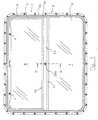
- Figure 1 is a front view from the inside of a first embodiment of a window for railway carriages according to the present invention;
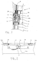
- Figure 2 is a partial vertical section of the window of the invention along line II-II of Figure 1;
- Figure 3 is an enlarged section view of the crank mechanism for actuating the pair of pins around which tiltable rotation of the window takes place;
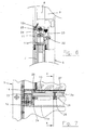
- Figure 4 is a partial section view of an end portion of the transverse structure of the window according to the invention;
- Figure 5 is a partial vertical section taken along line V-V of Figure 4;
- Figure 6 is a partial vertical section taken along line VI-VI of Figure 4;
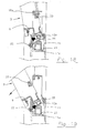
- Figure 7 is a partial section view of an end position of the window like Figure 4, but with the pin in the second position;
- Figure 8 is a partial vertical section taken along line VIII-VIII of Figure 4;
- Figure 9 is a partial vertical section, the same as that of Figure 8, wherein however the tiltable portion of the window has been opened;
- Figure 10 is a partial vertical section taken along line X-X of Figure 4;
- Figure 11 is a partial vertical section similar to that of Figure 10, wherein the tiltable portion of the window is fully tipped up;
- Figures 12 and 13 are views equivalent to Figures 2 and 3 of a different embodiment of the device for actuating sliding of the pins for rotation of the mobile part of the window, Figure 13 being a section taken along line XIII-XIII of Figure 12;
- Figure 14 is a section view taken along line XIV-XIV of Figure 15 of another embodiment relating to the device for controlling rotation of the mobile part of the window in the closure position;
- Figure 15 is a section taken along line XV-XV of the device illustrated in Figure 14;
- Figure 16 is a section view taken along line XVI-XVI of Figure 17 of the same embodiment of the device illustrated in Figures 14 and 15, but in the position which allows the mobile part of the window to be tipped up;
- Figure 17 is a section taken along line XVII-XVII of the device illustrated in Figure 16;
- Figures 18 and 19 illustrate the window according to the invention, in the version shown in Figures 14 and 17, in a tilted position and initial tipping respectively.
- Referring to Figure 1, 1 denotes generically a window of a railway carriage, which window is formed by a
fixed window portion 2 and by atiltable window portion 3 normally locked in a closed position and which can be released by staff on duty using thelocks 4 situated in the upper part thereof by means of a special key for allowing limited opening of the window in the case wherein the air-conditioning of the carriage is not in operation. - The structure of the window is, as a whole, of the conventional type and comprises a surround denoted by 5 and formed by an
external part 5a for resting on the window-space formed in the side wall of the carriage, and aninternal part 5b projecting internally from the outside one and acting as a support for aglass 7 of thefixed portion 2 of the window and as an abutment for thetiltable portion 3. The latter is in turn formed by a pane ofglass 8 bordered around the perimeter by aframe 9 hinged to atransverse structure 10, whereto the lower pane ofglass 7 is also attached. - Referring to Figure 2, the
transverse structure 10 is formed by a cross member orsection bar 11 with a substantially H shape for bordering below a groove tightly housing the upper edge of theglass 7. Thelower edge 9a of theframe 9, wherein the corresponding lower edge of theglass 8 is tightly housed, is engaged on a pair ofpins frame 9 can rotate, allowing tiltable opening of the window. As also shown in Figures 3 and 4, the twopins 12a,b are slidingly engaged inbushings 13 integral with thelower edge 9a of theframe 9 and, at the ends of thecross member 11, in respective housings 14 (only one is shown in the drawings) formed insupport blocks 15 attached by means ofscrews 16 to theinner part 11a of the H-shaped cross member 11. - In order to actuate axial sliding of the
pins 12a,b which move towards or apart from each other, an actuation device is provided, more particularly a crank mechanism with manual actuation integral with aprofile 23 and connected to the two opposite ends of thepins 12a,b. More specifically, the free ends of the twopins disk 19 by means of respective connectingrods disk 19.Disk 19 is integral with astem 20 pivotally supported by theprofile 23 and emerging frontally therefrom with one of itsheads 20a set up for actuation by means of a special key. - By rotating the
stem 20 and thedisk 19 integral therewith, it is possible to transmit a sliding movement to the twopins pins respective support blocks 15, to a second position, illustrated in Figures 7 and 10, wherein the ends of thepins 12a,b are fully disengaged therefrom. Rotation of thedisk 19 is contrasted elastically by aflat spring 21 which pushes against a perimeter flattenedpart 19a of thedisk 19. Theflattened part 19a is positioned at thespring 21 when thepins 12a,b are in the aforesaid first position, which is the normal position of said pins, preventing accidental or unauthorised rotations of thedisk 19. - Referring to Figures 4-7, the
cross member 11 is connected by means of ahinge 22 to theprofile 23, extending inside thesame cross member 11. At the ends of theprofile 23 twoshoulders 24 are attached (only one can be seen in the drawings), wherein aslot 25 is formed at thehousings 14 of theblocks 15 whereto theshoulders 24 are adjacent. Moreover theprofile 23 has at least two intermediate apertures 26 (only one can be seen in the drawings) with the function which is to be described herein below. - A
block 27 is attached to thepin 12a (the same applies for thepin 12b), wherefrom anappendage 28 extends (see also Figure 8), abutting on aridge 23a of theprofile 23. This condition occurs when thepins 12a,b are in their first position, i.e. with their ends engaged in thehousings 14 of theblocks 15. Theappendage 28 also constitutes an abutment element for theedge 9a of theframe 9 when the latter and theglass 8 attached thereto are rotated around thepins 12a,b. As shown in Figure 9, thelower edge 9a of theframe 9 abuts on theappendage 28 on the opposite side to theridge 23a of theprofile 23, effectively limiting rotation of theframe 9 to a preset angle (denoted by α). - As shown in Figures 7 and 10, by placing the
pins housings 14 of theblocks 15 and are positioned at theslot 25 formed in each of theshoulders 24, theappendage 28 of theblock 27 is positioned at theaperture 26 of theprofile 23. - Since the
slot 25 has a length longer than the diameter of thehousing 14 and extends towards theprofile 23, once the end of thepins 12a,b has disengaged from therelevant housing 14, said end goes to the base of theslot 25, causing lowering of thepins 12a,b and of theframe 9 integral thereto, while theappendage 28 is positioned in theaperture 26. Theframe 9 is lowered automatically, once the ends of thepins 12a,b are disengaged from thehousings 14, due to its own weight which automatically releases the frame from the locking devices denoted by 4 and situated in the upper part of the window. - In the condition described above the
frame 9 is free to rotate around thehinge 22, adopting a fully tipped condition illustrated in Figure 11, no longer being attached to thesupport blocks 15 by means of the ends of thepins 12a,b. - If, in addition to tipping, the
frame 9 also has to be removed from thewindow 1, a third position of thepins 12a,b can be provided wherein they can also be withdrawn from theslots 25. This can be obtained by defining two different extents of rotation of thedisk 19, corresponding to two different extents of sliding of thepins 12a,b. More particularly, with a first rotation, thepins 12a,b can be slid until they are disengaged from thehousings 14 of theblocks 15 and with a second subsequent rotation, to be performed if the tiltable portion also has to be removed, the ends of thepins 12a,b can be disengaged from theslots 25 of theshoulders 24. Another way of fully freeing theframe 9 also from theprofile 23, pivotally connected to thecross member 11, is to make theslot 25 in a form which is open at the top, so that tipping of theframe 9 also causes simultaneous sliding of the ends of thepins 12a,b along therespective slots 25 causing them to exit therefrom at the end of the tipping movement. This solution is not illustrated in detail, in that it is in itself obvious in light of the drawings. -
Seals lower edge 9a of theframe 9 and thecross member 11 on one side and theprofile 23 on the other. - Figures 12 and 13 illustrate a different embodiment of the device for actuating axial sliding of the
pins tiltable part 3 rotates. In these drawings the same components present in the previous drawings have the same reference numeral. In this embodiment thedisk 19, whereto thepins 12a,b are connected via the connectingrods lever 32, which can also be actuated by the user, if necessary, without having to wait for help by the staff in charge, provided with the special key for turning thedisk 19. Anelastic plate 31 with an overturned V portion which engages in thedisk 19 prevents free rotation of the same disk and hence axial sliding of thepins 12a,b, maintaining thetiltable part 3 in a closed position. On the other hand, by overcoming the elastic reaction of theplate 31, it is possible to disengage it from thedisk 19 to allow its rotation and hence axial sliding of the twopins 12a,b. - In the embodiment of the invention shown in Figures 1-11, the possibility of rotation around the
pins 12a,b of thetiltable portion 3 is controlled by the abutting of thelower edge 9a of itsframe 9 on theappendage 28 of theblock 27 integral with thepin 12a and, correspondingly, thepin 12b. In a different embodiment, illustrated in Figures 14 and 15, aplate 34 with aprojection 33 is attached laterally to theframe 9, holding theglass 8 of the window. Theblock 15, in which thehousing 14 for the end of thepin 12a (12b) is formed, extends inside thesurround 5 up to the height of theprojection 33 at which it is shaped with anangled edge 15a extending towards saidprojection 33. Figure 14 illustrates the relative position of theangled edge 15a and of theprojection 33 when thetiltable portion 3 is closed. Figure 18 illustrates the relative position of the two components when thetiltable portion 3 is open. In this condition theprojection 33 abuts on theangled edge 15a, locking the tiltable portion in an open position with the preset slant. - When the
pins housings 14 of theblock 15, following actuation of the disk 19 (by means of a special key or the lever 32), thetiltable portion 3 lowers as shown in Figures 16 and 17 so that theprojection 33 also lowers, bringing itself below theangled edge 15a of theblock 15. In this case rotation of thetiltable portion 3 around thepins 12a,b is no longer limited by the abutting between theprojection 33 and theangular edge 15a and can continue as shown in Figure 19, until thetiltable portion 3 is fully tipped. It will be noted that in this solution removal of thetiltable portion 3 once the position of full tipping has been achieved is not provided. Thanks to the distance between theprojection 33 and the axis of rotation of thepins 12a,b, the tensile stress resistance of thetiltable portion 3 in an open condition is improved. - From the foregoing it is clear that the window for railway carriages according to the present invention achieves in full the object set. It can in fact function as a normal window for air-conditioned carriages, since it can be locked in a closure position, and can be partially opened, in the case of non-functioning of the air-conditioning system, by actuating the
locking devices 4 and rotating thetiltable portion 3 of thewindow 1 around thepins 12a,b. The window according to the invention also allows full tipping of thetiltable portion 3 in case emergency conditions should occur simply by actuating with a special key thestem head 20a placed centrally in relation to the window on thecross member 11, or by means of thelever 32, to disengage the ends of thepins 12a,b from the respective housings integral with the fixed structure. If considered necessary, it is also possible to provide for complete removal of thetiltable portion 3 of the window. The invention therefore allows emergency apertures through the windows to be provided without the need to smash the glass. - Variations and/or modifications may be made to the window for railway vehicles according to the present invention without thereby departing from the spirit and scope of the invention as set forth in the appended claims.
Claims (13)
- Window with an opening of the tiltable type for railway carriages comprising a tiltable portion (3) hinged to a surround (5) thereof and means (4) for locking said tiltable portion in a closed condition, characterised in that said tiltable portion is hinged to said surround by means of a pair of aligned and axially sliding pins (12a,b) so as to define a first position, wherein they are engaged in housings (14) integral with said surround, and a second position wherein, following axial translation towards one another, they are disengaged therefrom, said tiltable portion being also hinged, parallel to said pair of pins, to an intermediate cross member (11) of said window integral with said surround (5), so that, when said pins are in said first position, said tiltable portion can only perform an angular movement of preset extent after manual disabling of said locking means, whereas, when they are placed in said second position, said tiltable portion rotates in relation to said cross member (11) until it is fully tipped, said locking means being disabled following lowering of said tiltable portion as a result of disengaging of the ends of the pins (12a,b) from the respective housings (14).
- Window according to claim 1, wherein said pair of pins is connected slidingly to the lower edge (9a) of said tiltable portion (3) and is linked to a device (17,18,19,32) for actuating their axial sliding movement to and from each other.
- Window according to claim 2, wherein said device comprises a manually actuated crank mechanism (17, 18, 19, 32) integral with a profile (23) hinged to said cross member (11) and connected to the two opposite ends of said pins (12a,b).
- Window according to claim 3, wherein said crank mechanism comprises a disc-shaped body (19) integral with a stem (20) supported by a profile (23) hinged to said cross member (11), connected eccentrically to two connecting rods (17,18) in a substantially diametrical position, said connecting rods being in turn connected to the opposite ends of said pins (12a,b), said crank mechanism being accessible via a head of said stem for actuation by means of a special key.
- Window according to claim 3, wherein said crank mechanism comprises a disc-shaped body (19) integral with a stem (20) supported by a profile (23) hinged to said cross member (11), connected eccentrically to two connecting rods (17,18) in a substantially diametric position, said connecting rods being in turn connected to the opposite ends of said pins (12a,b), said stem being integral with a lever (32) accessible for its actuation.
- Window according to claims 4 or 5, wherein the rotation of said disc-shaped body (19) is opposed elastically.
- Window according to any one of the previous claims, wherein the other ends of said pins are rotatingly and slidingly connected to supports (15) integral with said cross member (11).
- Window according to any one of the previous claims, wherein said cross member (11) is formed by a section bar with a substantially H shape, wherein a profile (23) is positioned, hinged thereto and integral with said pair of pins (12a,b) through a pair of end shoulders (24) having respective slots (25) in which in said pair of pins is engaged.
- Window according to claims 7 or 8, wherein said supports (15), integral with said section bar (11), have respective housings (14) for the ends of said pins (12a,b) aligned with said slots (25) of said shoulders (24), the length of said slots being greater than the diameter of said housings, said slots extending towards said profile.
- Window according to claim 9, wherein said profile has a longitudinal ridge (23a) and at least two apertures (26) which break up said ridge, said pins holding respective abutment elements (28) abutting on said ridge when said pins are in said first position, the lower edge (9a) of said tiltable portion abutting on said abutment element (28), on the side opposite said ridge (23a), after a limited angular movement of said tiltable portion, said abutment elements being engageable in said apertures when said pins are in said second position and are engaged in the slots of said shoulders, so that said tiltable portion can drive said profile (23) to rotate by means of said shoulders (24) around said section bar (11) until it is fully tipped.
- Window according to any one of the previous claims, wherein the slots (24) of said shoulders are closed and said pair of pins is designed to be placed in a third position wherein the ends of said pins are disengaged also from said slots to allow removal of the tiltable portion.
- Window according to any one of claims 1 to 10, wherein said slots (24) are open above so that, once said tiltable portion has been fully tipped, the ends of said pair of pins, in said second position, can be disengaged from said slots for removal of said tiltable portion.
- Window according to any one of claims 1 to 9, wherein said tiltable portion (3) comprises a frame (9), at the sides whereof a projection (33) is formed, said supports (15) extending as far as the height of said projection (33) and having there an angled edge (15a), said projection abutting on said angled edge when said pins (12a,b) are engaged in the respective housings (14) of said supports (15), so as to limit rotation of said tiltable portion and allowing instead rotation of said tiltable portion until it is tipped when the latter is lowered as a result of disengaging of said pins (12a,b) from the respective housings (14).
Applications Claiming Priority (2)
| Application Number | Priority Date | Filing Date | Title |
|---|---|---|---|
| ITFI20030285 | 2003-11-05 | ||
| IT000285A ITFI20030285A1 (en) | 2003-11-05 | 2003-11-05 | WINDOW WINDOW WITH VASISTAS OPENING, WITH TOTAL ROLLOVATION AND REMOVAL IN EMERGENCY SITUATIONS, FOR RAILWAY CARRIAGES |
Publications (2)
| Publication Number | Publication Date |
|---|---|
| EP1529708A1 true EP1529708A1 (en) | 2005-05-11 |
| EP1529708B1 EP1529708B1 (en) | 2008-07-16 |
Family
ID=34430730
Family Applications (1)
| Application Number | Title | Priority Date | Filing Date |
|---|---|---|---|
| EP04425608A Expired - Lifetime EP1529708B1 (en) | 2003-11-05 | 2004-08-04 | Window with an opening of the tiltable type, and with full tipping and removal in emergency situations, for railway carriages |
Country Status (4)
| Country | Link |
|---|---|
| EP (1) | EP1529708B1 (en) |
| AT (1) | ATE401224T1 (en) |
| DE (1) | DE602004015044D1 (en) |
| IT (1) | ITFI20030285A1 (en) |
Cited By (5)
| Publication number | Priority date | Publication date | Assignee | Title |
|---|---|---|---|---|
| EP1958809A1 (en) * | 2007-02-13 | 2008-08-20 | Clark Equipment Company | Window arrangement for a construction vehicle |
| US8091955B2 (en) | 2009-04-16 | 2012-01-10 | Clark Equipment Company | Sliding window for work vehicle cab |
| EP2559604A4 (en) * | 2010-05-10 | 2013-05-01 | Tangshan Railway Vehicle Co | Emergency passage window for railway carriage |
| FR3057842A1 (en) * | 2016-10-26 | 2018-04-27 | Airbus Safran Launchers Sas | DEVICE FOR THE EMERGENCY EXHAUST OF THERMOPLASTIC BAYS |
| WO2021191517A1 (en) * | 2020-03-25 | 2021-09-30 | Saint-Gobain Glass France | System for fastening a side glazing of a means of transport with a lock |
Citations (3)
| Publication number | Priority date | Publication date | Assignee | Title |
|---|---|---|---|---|
| US2639790A (en) * | 1950-01-26 | 1953-05-26 | James G Reitzel | Emergency exit window |
| US4313280A (en) * | 1980-04-10 | 1982-02-02 | The Adams & Westlake Company | Quick opening latch arrangement for hinged vehicle windows |
| US20030107221A1 (en) * | 2001-12-07 | 2003-06-12 | Dura Global Technologies, Inc. | Egress window latching mechanism |
-
2003
- 2003-11-05 IT IT000285A patent/ITFI20030285A1/en unknown
-
2004
- 2004-08-04 DE DE602004015044T patent/DE602004015044D1/en not_active Expired - Fee Related
- 2004-08-04 EP EP04425608A patent/EP1529708B1/en not_active Expired - Lifetime
- 2004-08-04 AT AT04425608T patent/ATE401224T1/en not_active IP Right Cessation
Patent Citations (3)
| Publication number | Priority date | Publication date | Assignee | Title |
|---|---|---|---|---|
| US2639790A (en) * | 1950-01-26 | 1953-05-26 | James G Reitzel | Emergency exit window |
| US4313280A (en) * | 1980-04-10 | 1982-02-02 | The Adams & Westlake Company | Quick opening latch arrangement for hinged vehicle windows |
| US20030107221A1 (en) * | 2001-12-07 | 2003-06-12 | Dura Global Technologies, Inc. | Egress window latching mechanism |
Cited By (7)
| Publication number | Priority date | Publication date | Assignee | Title |
|---|---|---|---|---|
| EP1958809A1 (en) * | 2007-02-13 | 2008-08-20 | Clark Equipment Company | Window arrangement for a construction vehicle |
| US7758104B2 (en) | 2007-02-13 | 2010-07-20 | Clark Equipment Company | Window arrangement for a construction vehicle |
| US8091955B2 (en) | 2009-04-16 | 2012-01-10 | Clark Equipment Company | Sliding window for work vehicle cab |
| EP2559604A4 (en) * | 2010-05-10 | 2013-05-01 | Tangshan Railway Vehicle Co | Emergency passage window for railway carriage |
| FR3057842A1 (en) * | 2016-10-26 | 2018-04-27 | Airbus Safran Launchers Sas | DEVICE FOR THE EMERGENCY EXHAUST OF THERMOPLASTIC BAYS |
| WO2021191517A1 (en) * | 2020-03-25 | 2021-09-30 | Saint-Gobain Glass France | System for fastening a side glazing of a means of transport with a lock |
| FR3108576A1 (en) * | 2020-03-25 | 2021-10-01 | Saint-Gobain Glass France | SYSTEM FOR FIXING A SIDE GLASS FOR MEANS OF TRANSPORT WITH A LOCK |
Also Published As
| Publication number | Publication date |
|---|---|
| DE602004015044D1 (en) | 2008-08-28 |
| ATE401224T1 (en) | 2008-08-15 |
| ITFI20030285A1 (en) | 2005-05-06 |
| EP1529708B1 (en) | 2008-07-16 |
Similar Documents
| Publication | Publication Date | Title |
|---|---|---|
| EP1041229B1 (en) | Cab window lock system | |
| EP2923019B1 (en) | Disassemblable hinge with a safety catch | |
| ES2258806T3 (en) | LOCKING SYSTEM FOR TILTING AND ROTATING WINDOW. | |
| US20080040978A1 (en) | Hinge/Tilt Window Driven by an Electric Motor and Comprising a Feed Chain | |
| EP1529708B1 (en) | Window with an opening of the tiltable type, and with full tipping and removal in emergency situations, for railway carriages | |
| JPH04212626A (en) | Vehicle roof | |
| KR100749894B1 (en) | Elevating Sliding System Window | |
| US6932395B1 (en) | Window assembly with release mechanism | |
| ES2699915T3 (en) | Safety turn mechanism | |
| ES2238977T3 (en) | CLOSURE DEVICE FOR A SIDE DOOR OF A MOTOR VEHICLE AND VEHICLE EQUIPPED WITH SUCH DEVICE. | |
| PL201187B1 (en) | Fitting for a window or door | |
| JP4151564B2 (en) | Horizontal axis rotary window | |
| JPH031572Y2 (en) | ||
| HU223252B1 (en) | Opening-limiting fitting for doors and windows | |
| NL2014770B1 (en) | Security device for a window. | |
| JP3885687B2 (en) | Blind device | |
| JP2005163529A (en) | Lateral-axis rotary window | |
| KR100462401B1 (en) | Door checker capable of controlling the open angle of door | |
| JP4376024B2 (en) | Opening and closing mechanism of rear side panel in work vehicle | |
| JP2610791B2 (en) | Door locking device | |
| KR100369036B1 (en) | a window glass opening device of vehicle in an emergency | |
| KR100552178B1 (en) | Vehicle door key cylinder to prevent theft | |
| KR100776335B1 (en) | Emergency escape switch of screen door | |
| EP1748147B1 (en) | Safety brake for gates | |
| JPH0435495Y2 (en) |
Legal Events
| Date | Code | Title | Description |
|---|---|---|---|
| PUAI | Public reference made under article 153(3) epc to a published international application that has entered the european phase |
Free format text: ORIGINAL CODE: 0009012 |
|
| AK | Designated contracting states |
Kind code of ref document: A1 Designated state(s): AT BE BG CH CY CZ DE DK EE ES FI FR GB GR HU IE IT LI LU MC NL PL PT RO SE SI SK TR |
|
| AX | Request for extension of the european patent |
Extension state: AL HR LT LV MK |
|
| 17P | Request for examination filed |
Effective date: 20050714 |
|
| AKX | Designation fees paid |
Designated state(s): AT BE BG CH CY CZ DE DK EE ES FI FR GB GR HU IE IT LI LU MC NL PL PT RO SE SI SK TR |
|
| GRAP | Despatch of communication of intention to grant a patent |
Free format text: ORIGINAL CODE: EPIDOSNIGR1 |
|
| GRAS | Grant fee paid |
Free format text: ORIGINAL CODE: EPIDOSNIGR3 |
|
| GRAA | (expected) grant |
Free format text: ORIGINAL CODE: 0009210 |
|
| AK | Designated contracting states |
Kind code of ref document: B1 Designated state(s): AT BE BG CH CY CZ DE DK EE ES FI FR GB GR HU IE IT LI LU MC NL PL PT RO SE SI SK TR |
|
| REG | Reference to a national code |
Ref country code: GB Ref legal event code: FG4D |
|
| REG | Reference to a national code |
Ref country code: CH Ref legal event code: EP |
|
| REF | Corresponds to: |
Ref document number: 602004015044 Country of ref document: DE Date of ref document: 20080828 Kind code of ref document: P |
|
| REG | Reference to a national code |
Ref country code: IE Ref legal event code: FG4D |
|
| NLV1 | Nl: lapsed or annulled due to failure to fulfill the requirements of art. 29p and 29m of the patents act | ||
| PG25 | Lapsed in a contracting state [announced via postgrant information from national office to epo] |
Ref country code: ES Free format text: LAPSE BECAUSE OF FAILURE TO SUBMIT A TRANSLATION OF THE DESCRIPTION OR TO PAY THE FEE WITHIN THE PRESCRIBED TIME-LIMIT Effective date: 20081027 Ref country code: NL Free format text: LAPSE BECAUSE OF FAILURE TO SUBMIT A TRANSLATION OF THE DESCRIPTION OR TO PAY THE FEE WITHIN THE PRESCRIBED TIME-LIMIT Effective date: 20080716 Ref country code: PT Free format text: LAPSE BECAUSE OF FAILURE TO SUBMIT A TRANSLATION OF THE DESCRIPTION OR TO PAY THE FEE WITHIN THE PRESCRIBED TIME-LIMIT Effective date: 20081216 |
|
| PG25 | Lapsed in a contracting state [announced via postgrant information from national office to epo] |
Ref country code: SI Free format text: LAPSE BECAUSE OF FAILURE TO SUBMIT A TRANSLATION OF THE DESCRIPTION OR TO PAY THE FEE WITHIN THE PRESCRIBED TIME-LIMIT Effective date: 20080716 Ref country code: FI Free format text: LAPSE BECAUSE OF FAILURE TO SUBMIT A TRANSLATION OF THE DESCRIPTION OR TO PAY THE FEE WITHIN THE PRESCRIBED TIME-LIMIT Effective date: 20080716 Ref country code: BG Free format text: LAPSE BECAUSE OF FAILURE TO SUBMIT A TRANSLATION OF THE DESCRIPTION OR TO PAY THE FEE WITHIN THE PRESCRIBED TIME-LIMIT Effective date: 20081016 Ref country code: AT Free format text: LAPSE BECAUSE OF FAILURE TO SUBMIT A TRANSLATION OF THE DESCRIPTION OR TO PAY THE FEE WITHIN THE PRESCRIBED TIME-LIMIT Effective date: 20080716 |
|
| PG25 | Lapsed in a contracting state [announced via postgrant information from national office to epo] |
Ref country code: MC Free format text: LAPSE BECAUSE OF NON-PAYMENT OF DUE FEES Effective date: 20080831 Ref country code: BE Free format text: LAPSE BECAUSE OF FAILURE TO SUBMIT A TRANSLATION OF THE DESCRIPTION OR TO PAY THE FEE WITHIN THE PRESCRIBED TIME-LIMIT Effective date: 20080716 |
|
| REG | Reference to a national code |
Ref country code: CH Ref legal event code: PL |
|
| PG25 | Lapsed in a contracting state [announced via postgrant information from national office to epo] |
Ref country code: EE Free format text: LAPSE BECAUSE OF FAILURE TO SUBMIT A TRANSLATION OF THE DESCRIPTION OR TO PAY THE FEE WITHIN THE PRESCRIBED TIME-LIMIT Effective date: 20080716 Ref country code: DK Free format text: LAPSE BECAUSE OF FAILURE TO SUBMIT A TRANSLATION OF THE DESCRIPTION OR TO PAY THE FEE WITHIN THE PRESCRIBED TIME-LIMIT Effective date: 20080716 |
|
| PLBE | No opposition filed within time limit |
Free format text: ORIGINAL CODE: 0009261 |
|
| STAA | Information on the status of an ep patent application or granted ep patent |
Free format text: STATUS: NO OPPOSITION FILED WITHIN TIME LIMIT |
|
| PG25 | Lapsed in a contracting state [announced via postgrant information from national office to epo] |
Ref country code: CZ Free format text: LAPSE BECAUSE OF FAILURE TO SUBMIT A TRANSLATION OF THE DESCRIPTION OR TO PAY THE FEE WITHIN THE PRESCRIBED TIME-LIMIT Effective date: 20080716 Ref country code: SK Free format text: LAPSE BECAUSE OF FAILURE TO SUBMIT A TRANSLATION OF THE DESCRIPTION OR TO PAY THE FEE WITHIN THE PRESCRIBED TIME-LIMIT Effective date: 20080716 Ref country code: RO Free format text: LAPSE BECAUSE OF FAILURE TO SUBMIT A TRANSLATION OF THE DESCRIPTION OR TO PAY THE FEE WITHIN THE PRESCRIBED TIME-LIMIT Effective date: 20080716 |
|
| 26N | No opposition filed |
Effective date: 20090417 |
|
| GBPC | Gb: european patent ceased through non-payment of renewal fee |
Effective date: 20081016 |
|
| PG25 | Lapsed in a contracting state [announced via postgrant information from national office to epo] |
Ref country code: CH Free format text: LAPSE BECAUSE OF NON-PAYMENT OF DUE FEES Effective date: 20080831 Ref country code: LI Free format text: LAPSE BECAUSE OF NON-PAYMENT OF DUE FEES Effective date: 20080831 |
|
| REG | Reference to a national code |
Ref country code: FR Ref legal event code: ST Effective date: 20090630 |
|
| PG25 | Lapsed in a contracting state [announced via postgrant information from national office to epo] |
Ref country code: IE Free format text: LAPSE BECAUSE OF NON-PAYMENT OF DUE FEES Effective date: 20080804 |
|
| PG25 | Lapsed in a contracting state [announced via postgrant information from national office to epo] |
Ref country code: IT Free format text: LAPSE BECAUSE OF FAILURE TO SUBMIT A TRANSLATION OF THE DESCRIPTION OR TO PAY THE FEE WITHIN THE PRESCRIBED TIME-LIMIT Effective date: 20080716 Ref country code: DE Free format text: LAPSE BECAUSE OF NON-PAYMENT OF DUE FEES Effective date: 20090303 |
|
| PG25 | Lapsed in a contracting state [announced via postgrant information from national office to epo] |
Ref country code: FR Free format text: LAPSE BECAUSE OF NON-PAYMENT OF DUE FEES Effective date: 20080901 |
|
| PG25 | Lapsed in a contracting state [announced via postgrant information from national office to epo] |
Ref country code: GB Free format text: LAPSE BECAUSE OF NON-PAYMENT OF DUE FEES Effective date: 20081016 |
|
| PG25 | Lapsed in a contracting state [announced via postgrant information from national office to epo] |
Ref country code: SE Free format text: LAPSE BECAUSE OF FAILURE TO SUBMIT A TRANSLATION OF THE DESCRIPTION OR TO PAY THE FEE WITHIN THE PRESCRIBED TIME-LIMIT Effective date: 20081016 |
|
| PG25 | Lapsed in a contracting state [announced via postgrant information from national office to epo] |
Ref country code: PL Free format text: LAPSE BECAUSE OF FAILURE TO SUBMIT A TRANSLATION OF THE DESCRIPTION OR TO PAY THE FEE WITHIN THE PRESCRIBED TIME-LIMIT Effective date: 20080716 |
|
| PG25 | Lapsed in a contracting state [announced via postgrant information from national office to epo] |
Ref country code: CY Free format text: LAPSE BECAUSE OF FAILURE TO SUBMIT A TRANSLATION OF THE DESCRIPTION OR TO PAY THE FEE WITHIN THE PRESCRIBED TIME-LIMIT Effective date: 20080716 Ref country code: LU Free format text: LAPSE BECAUSE OF NON-PAYMENT OF DUE FEES Effective date: 20080804 Ref country code: HU Free format text: LAPSE BECAUSE OF FAILURE TO SUBMIT A TRANSLATION OF THE DESCRIPTION OR TO PAY THE FEE WITHIN THE PRESCRIBED TIME-LIMIT Effective date: 20090117 |
|
| PG25 | Lapsed in a contracting state [announced via postgrant information from national office to epo] |
Ref country code: TR Free format text: LAPSE BECAUSE OF FAILURE TO SUBMIT A TRANSLATION OF THE DESCRIPTION OR TO PAY THE FEE WITHIN THE PRESCRIBED TIME-LIMIT Effective date: 20080716 |
|
| PG25 | Lapsed in a contracting state [announced via postgrant information from national office to epo] |
Ref country code: GR Free format text: LAPSE BECAUSE OF FAILURE TO SUBMIT A TRANSLATION OF THE DESCRIPTION OR TO PAY THE FEE WITHIN THE PRESCRIBED TIME-LIMIT Effective date: 20081017 |