EP1529675A2 - Control strategy for active torque control - Google Patents
Control strategy for active torque control Download PDFInfo
- Publication number
- EP1529675A2 EP1529675A2 EP04026278A EP04026278A EP1529675A2 EP 1529675 A2 EP1529675 A2 EP 1529675A2 EP 04026278 A EP04026278 A EP 04026278A EP 04026278 A EP04026278 A EP 04026278A EP 1529675 A2 EP1529675 A2 EP 1529675A2
- Authority
- EP
- European Patent Office
- Prior art keywords
- torque
- shaft
- clutch
- transfer
- drive
- Prior art date
- Legal status (The legal status is an assumption and is not a legal conclusion. Google has not performed a legal analysis and makes no representation as to the accuracy of the status listed.)
- Granted
Links
- 238000011217 control strategy Methods 0.000 title description 18
- 230000007246 mechanism Effects 0.000 claims abstract description 24
- 230000005540 biological transmission Effects 0.000 claims description 51
- 238000000034 method Methods 0.000 claims 8
- 230000001276 controlling effect Effects 0.000 description 11
- 230000008878 coupling Effects 0.000 description 11
- 238000010168 coupling process Methods 0.000 description 11
- 238000005859 coupling reaction Methods 0.000 description 11
- 230000004044 response Effects 0.000 description 5
- 230000000875 corresponding effect Effects 0.000 description 4
- 230000006870 function Effects 0.000 description 4
- 230000003044 adaptive effect Effects 0.000 description 3
- 230000008901 benefit Effects 0.000 description 2
- 238000005516 engineering process Methods 0.000 description 2
- 230000003278 mimic effect Effects 0.000 description 2
- 230000004048 modification Effects 0.000 description 2
- 238000012986 modification Methods 0.000 description 2
- 230000009471 action Effects 0.000 description 1
- 230000003466 anti-cipated effect Effects 0.000 description 1
- 230000008859 change Effects 0.000 description 1
- 238000010276 construction Methods 0.000 description 1
- 230000002596 correlated effect Effects 0.000 description 1
- 230000004069 differentiation Effects 0.000 description 1
- 230000000694 effects Effects 0.000 description 1
- 230000002035 prolonged effect Effects 0.000 description 1
- 230000009467 reduction Effects 0.000 description 1
Images


Classifications
-
- B—PERFORMING OPERATIONS; TRANSPORTING
- B60—VEHICLES IN GENERAL
- B60K—ARRANGEMENT OR MOUNTING OF PROPULSION UNITS OR OF TRANSMISSIONS IN VEHICLES; ARRANGEMENT OR MOUNTING OF PLURAL DIVERSE PRIME-MOVERS IN VEHICLES; AUXILIARY DRIVES FOR VEHICLES; INSTRUMENTATION OR DASHBOARDS FOR VEHICLES; ARRANGEMENTS IN CONNECTION WITH COOLING, AIR INTAKE, GAS EXHAUST OR FUEL SUPPLY OF PROPULSION UNITS IN VEHICLES
- B60K23/00—Arrangement or mounting of control devices for vehicle transmissions, or parts thereof, not otherwise provided for
- B60K23/08—Arrangement or mounting of control devices for vehicle transmissions, or parts thereof, not otherwise provided for for changing number of driven wheels, for switching from driving one axle to driving two or more axles
- B60K23/0808—Arrangement or mounting of control devices for vehicle transmissions, or parts thereof, not otherwise provided for for changing number of driven wheels, for switching from driving one axle to driving two or more axles for varying torque distribution between driven axles, e.g. by transfer clutch
-
- B—PERFORMING OPERATIONS; TRANSPORTING
- B60—VEHICLES IN GENERAL
- B60W—CONJOINT CONTROL OF VEHICLE SUB-UNITS OF DIFFERENT TYPE OR DIFFERENT FUNCTION; CONTROL SYSTEMS SPECIALLY ADAPTED FOR HYBRID VEHICLES; ROAD VEHICLE DRIVE CONTROL SYSTEMS FOR PURPOSES NOT RELATED TO THE CONTROL OF A PARTICULAR SUB-UNIT
- B60W2510/00—Input parameters relating to a particular sub-units
- B60W2510/06—Combustion engines, Gas turbines
- B60W2510/0657—Engine torque
-
- B—PERFORMING OPERATIONS; TRANSPORTING
- B60—VEHICLES IN GENERAL
- B60W—CONJOINT CONTROL OF VEHICLE SUB-UNITS OF DIFFERENT TYPE OR DIFFERENT FUNCTION; CONTROL SYSTEMS SPECIALLY ADAPTED FOR HYBRID VEHICLES; ROAD VEHICLE DRIVE CONTROL SYSTEMS FOR PURPOSES NOT RELATED TO THE CONTROL OF A PARTICULAR SUB-UNIT
- B60W2710/00—Output or target parameters relating to a particular sub-units
- B60W2710/02—Clutches
- B60W2710/027—Clutch torque
Definitions
- the present invention relates generally to power transfer systems for controlling the distribution of drive torque between the front and rear drivelines of a four-wheel drive vehicle. More particularly, the present invention is directed to a power transmission device having a torque transfer mechanism equipped with a friction clutch, a power-operated clutch actuator, and a control system employing an active torque control strategy for controlling actuation of the power-operated clutch actuator.
- a power transmission device is operably installed between the primary and secondary drivelines.
- Such power transmission devices are typically equipped with a torque transfer mechanism for selectively and/or automatically transferring drive torque from the primary driveline to the secondary driveline to establish a four-wheel drive mode of operation.
- the torque transfer mechanism may include a dog-type lock-up clutch that can be selectively engaged for rigidly coupling the secondary driveline to the primary driveline to establish a locked or "part-time" four-wheel drive mode.
- drive torque is only delivered to the primary driveline when the lock-up clutch is released for establishing a two-wheel drive mode.
- a modern trend in four-wheel drive motor vehicles is to equip the power transmission device with a transfer clutch in place of the lock-up clutch.
- the transfer clutch is operable for automatically directing drive torque to the secondary wheels, without any input or action on the part of the vehicle operator, when traction is lost at the primary wheels for establishing an "on-demand" four-wheel drive mode.
- the transfer clutch includes a multi-plate clutch assembly that is installed between the primary and secondary drivelines and a clutch actuator for generating a clutch engagement force that is applied to the multi-plate clutch assembly.
- the clutch actuator In passive-type transfer clutch applications, the clutch actuator generates the clutch engagement force in response to the magnitude of the speed difference between the primary and secondary wheels.
- the clutch actuator includes a power-operated device that is actuated in response to electric control signals sent from an electronic control unit (ECU).
- ECU electronice control unit
- the ECU receives input signals from speed sensors associated with the primary and secondary drivelines as well as from other vehicle sensors and generates the control signal based thereon.
- speed sensors associated with the primary and secondary drivelines as well as from other vehicle sensors and generates the control signal based thereon.
- a large number of on-demand power transmission devices have been developed with an electrically-controlled clutch actuator that can regulate the amount of drive torque transferred to the secondary driveline as a function of the value of the electrical control signal applied thereto.
- the transfer clutch employs an electromagnetic clutch as the power-operated clutch actuator.
- U.S. Patent No. 5,407,024 discloses an electromagnetic coil that is incrementally activated to control movement of a ball-ramp drive assembly for applying a clutch engagement force on the multi-plate clutch assembly.
- Japanese Laid-open Patent Application No. 62-18117 discloses a transfer clutch equipped with an electromagnetic actuator for directly controlling actuation of the multi-plate clutch pack assembly.
- the transfer clutch can employ an electric motor and a drive assembly as its power-operated clutch actuator.
- U.S. Patent No. 5,323,871 discloses an on-demand transfer case having a transfer clutch equipped with an electric motor that controls rotation of a sector plate which, in turn, controls pivotal movement of a lever arm that is operable for applying the clutch engagement force to the multi-plate clutch assembly.
- Japanese Laid-open Patent Application No. 63-66927 discloses a transfer clutch which uses an electric motor to rotate one cam plate of a ball-ramp operator for engaging the multi-plate clutch assembly.
- 4,895,236 and 5,423,235 respectively disclose a transfer case equipped with a transfer clutch having an electric motor driving a reduction gearset for controlling movement of a ball screw operator and a ball-ramp operator which, in turn, apply the clutch engagement force to the clutch pack.
- full-time power transmission devices typically operate in the two-wheel drive mode and are adaptively shifted into the four-wheel drive mode in response to lost traction at the primary wheels.
- full-time power transmission devices utilize a center or interaxle differential between the primary and secondary drivelines to continuously transfer drive torque therebetween while also accommodating speed differentiation between the drivelines.
- many full-time power transmission devices are also equipped with a biasing clutch for limiting interaxle slip and varying the distribution ratio of the drive torque transmitted across the interaxle differential to the primary and secondary drivelines.
- many biasing clutches include a multi-plate clutch assembly and a power-operated clutch actuator that is adaptively controlled by a control system to vary engagement of the clutch assembly.
- the power transfer system of the present invention includes a power transmission device having a torque transfer mechanism equipped with a multi-plate clutch assembly operably installed between the front and rear drivelines, power-operated clutch actuator, and a control system using a strategy for providing active full-time torque control.
- An additional object of the present invention is to adaptively control actuation of the power-operated clutch actuator using the full-time torque control strategy to maintain a predetermined torque distribution ratio between the front and rear drivelines without the use of an interaxle differential assembly.
- the power transfer system includes a transfer case for use in a four-wheel drive motor vehicle having a powertrain and first and second drivelines, and a control system utilizing an active full-time torque control strategy.
- the transfer case includes a first shaft driven by the powertrain and which is adapted for connection to the first driveline, a second shaft adapted for connection to the second driveline, and a torque transfer mechanism.
- the torque transfer mechanism includes a friction clutch operably disposed between the first shaft and the second shaft, and a power-operated clutch actuator for generating and applying a clutch engagement force on the friction clutch.
- the control system includes vehicle sensors and a controller to control actuation of the clutch actuator.
- the controller uses signals from the various vehicle sensors to calculate a desired or "targeted" torque value to be transferred through the friction clutch to the second shaft for maintaining the predetermined front/rear torque distribution ratio.
- the controller generates a control signal based on the targeted torque value.
- the controller thereafter delivers the control signal to the power-operated clutch actuator for engaging the friction clutch.
- a coupling assembly is equipped with the torque transfer mechanism for automatically transferring drive torque from the first driveline to the second driveline utilizing the active full-time torque control strategy of the present invention.
- the torque transfer mechanism is operably associated with a power transfer unit for automatically transferring drive torque from the first driveline to the second driveline.
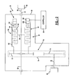
- Figure 1 illustrates the drivetrain of a four-wheel drive vehicle equipped with the power transmission device of the present invention
- Figure 2 is a sectional view of a transfer case associated with the drivetrain shown in Figure 1 and which is equipped with a torque transfer mechanism according to the present invention
- Figure 3 is a flow chart illustrating steps performed by the control system of the present invention.
- Figure 4 is a look-up table correlating a transmission gear to a transmission gear ratio
- Figure 5 is a look-up table correlating a torque converter speed ratio to a torque converter torque ratio
- Figure 6 is a look-up table correlating a desired torque value to a clutch actuator position
- Figure 7 is a look-up table correlating a steering angle value to a clutch actuator position offset value
- Figure 8 is a schematic illustration of an alternative driveline for a four-wheel drive motor vehicle equipped with a power transmission device of the present invention.
- FIGS 9 through 10 are schematic views of additional embodiments of power transmission devices equipped with the torque transfer mechanism of the present invention.
- the present invention is directed to a power transfer system utilizing a torque control strategy for adaptively controlling actuation of a torque transfer mechanism for controlling the drive torque transferred from a first rotary member to a second rotary member.
- the torque transfer mechanism finds particular application in power transmission devices for use in four-wheel drive motor vehicles such as, for example, a transfer clutch in a transfer case, a power take-off unit, or an in-line torque coupling.
- a drivetrain 10 for a four-wheel drive vehicle includes a first driveline 12, a second driveline 14, and a powertrain 16 for delivering rotary tractive power (i.e., drive torque) to the first and second drivelines.
- first driveline 12 is the rear driveline while second driveline 14 is the front driveline.
- Powertrain 16 includes an engine 18, a multi-speed transmission 20, and a power transmission device, hereinafter referred to as transfer case 22.
- Rear driveline 12 includes a pair of rear wheels 24 connected at opposite ends of a rear axle assembly 26 having a rear differential 28 coupled to one end of a rear propshaft 30, the opposite end of which is coupled to a rear output shaft 32 of transfer case 22.
- front driveline 14 includes a pair of front wheels 34 connected at opposite ends of a front axle assembly 36 having a front differential 38 coupled to one end of a front propshaft 40, the opposite end of which is coupled to a front output shaft 42 of transfer case 22.
- drivetrain 10 is shown to further include an electronically-controlled power transfer system for adaptively controlling the torque distribution between the front and rear drivelines.
- transfer case 22 is equipped with a transfer clutch 50 that can be selectively engaged for transferring drive torque from rear output shaft 32 to front output shaft 42.
- the power transfer system further includes a power-operated clutch actuator 52 for actuating transfer clutch 50, and a control system having vehicle sensors 54 for detecting certain dynamic and operational characteristics of the motor vehicle, a mode selector 56 permitting the vehicle operator to select one of the available drive modes, and a controller 58 for controlling actuation of clutch actuator 52 in response to input signals from vehicle sensors 54 and mode selector 56.
- mode selector 56 It is contemplated that as many as three different operative drive modes could be made available for selection via mode selector 56.
- a two-wheel drive (2WD) mode is established when transfer clutch 50 is released such that drive torque is only transmitted from powertrain 16 to rear driveline 12.
- a locked or part-time four-wheel drive (4WD) mode is established when transfer clutch 50 is fully engaged such that drive torque is transmitted equally to both drivelines.
- an allwheel drive (AWD) mode is established when power-operated clutch actuator 52 is adaptively controlled for controlling engagement of transfer clutch 50.
- AWD allwheel drive
- an active full-time torque control strategy is utilized by the control system when the AWD mode is selected. This control strategy is intended to mimic operation of an interaxle differential by maintaining a predetermined torque distribution ratio between the front and rear drivelines.
- Transfer case 22 is schematically shown in Figure 2 to include a housing 60 from which rear output shaft 32 is rotatably supported.
- Rear output shaft 32 includes a first end segment 62 adapted for connection to the output shaft of transmission 20 and a second end segment 64 to which a yoke 66 is secured for connection to rear propshaft 30.
- Front output shaft 42 is likewise rotatably supported in housing 60 and includes a yoke segment 68 adapted for connection to front propshaft 40.
- Transfer clutch 50 is operably arranged to transfer rotary power (i.e., drive torque) from rear output shaft 32 to front output shaft 42 through a transfer assembly 70.
- Transfer assembly 70 includes a first sprocket 72, a second sprocket 74, and a power chain 76 that is in driving engagement with first sprocket 72 and second sprocket 74.
- First sprocket 72 is rotatably supported on rear output shaft 32 while second sprocket 74 is coupled for rotation with front output shaft 42.
- Transfer clutch 50 includes a multi-plate friction clutch assembly 90.
- Clutch assembly 90 is shown to include a clutch hub 94 fixed for rotation with rear output shaft 32, a clutch drum 100 fixed for rotation with first sprocket 72, and a multi-plate clutch pack 104 operably disposed between hub 94 and drum 100.
- Clutch pack 104 includes a set of outer clutch plates 106 that are splined for rotation with and axial movement on drum 100.
- Clutch pack 104 also includes a set of inner clutch plates 108 that are splined for rotation with and axial movement on clutch hub 94.
- Clutch assembly 90 also includes a pressure plate 112 arranged to exert a compressive clutch engagement force on clutch pack 104.
- Pressure plate 112 is axially moveable relative to clutch pack 104 through a range of travel defined between a first or “released” position and a second or “locked” position. With pressure plate 112 in its released position, a minimum clutch engagement force is exerted on clutch pack 104 such that virtually no drive torque is transferred from rear output shaft 32 through clutch assembly 90 and transfer assembly 70 to front output shaft 42, thereby establishing the 2WD mode.
- pressure plate 112 in its locked position causes a maximum clutch engagement force to be applied to clutch pack 104 such that front output shaft 42 is, in effect, coupled for common rotation with rear output shaft 32, thereby establishing the 4WD mode.
- Accurate control of the position of pressure plate 112 between its released and locked positions permits adaptive regulation of the amount of drive torque transferred from rear output shaft 32 to front output shaft 42, thereby establishing the adaptive AWD mode.
- Clutch actuator 52 is provided for moving pressure plate 112 between its released and locked positions. While only a schematic version of actuator 52 is depicted in the drawings, one skilled in the art will appreciate that many types of power-operated actuator devices may be controlled using the torque control strategy of the present invention.
- clutch actuator 52 includes a power unit 116 and an apply operator device 118.
- Power unit 116 is adapted to receive electric control signals from controller 58 and generate an output force or torque in response thereto.
- a preferred power unit 116 is an electric motor having a rotary output.
- Apply operator device 118 is adapted to convert and amplify the output of power unit 116 into a linear thrust force that is applied to pressure plate 112 for causing movement thereof between its released and locked positions.
- Suitable apply operator devices include ball ramps, ball screws, sector-driven pivoting lever systems, and other similar devices.
- One example of a suitable clutch actuator 52 is shown and described in commonlyowned U.S. Patent No. 6,484,857 which is hereby incorporated by reference.
- control strategy includes a sequence of steps which function to prevent wheel slip while still providing drive torque to as many wheels as possible to help maintain vehicle traction and stability.
- controller 58 controls actuation of clutch actuator 52 in an attempt to simulate or "mimic" the operation of an interaxle differential by maintaining a desired torque split between the front and rear drivelines.
- control strategy of the present invention is advantageous over previous on-demand systems and full-time systems equipped with mechanical differentials in that slip need not be created for the power transfer system to transfer torque to the drivelines. Therefore, vehicle traction and stability is greatly improved.
- drivetrain 10 is equipped with a variety of sensors that provide signals to controller 58.
- an engine speed sensor 126 generates a signal based on the rotational speed of engine 18.
- An engine torque signal shown schematically as sensor 128, is a signal calculated by the engine controller (not shown) that is indicative of the engine torque produced by engine 18.
- a gear position signal shown as sensor 130, is a signal from the transmission controller (not shown) indicative of the present gear in which transmission 20 is operating.
- a first speed sensor 132 generates a signal based on the rotational speed of rear output shaft 32 while a second speed sensor 134 generates a signal based on the rotational speed of front output shaft 42.
- a steering angle sensor 136 generates a signal based on the present steering angle of front wheels 34.
- a position sensor 138 generates a signal based on the linear or rotary position of a moveable component associated with transfer clutch 50 or clutch actuator 52 which is indicative of the current position of pressure plate 112 relative to clutch pack 104.
- first speed sensor 132 provides a signal indicative of transfer case output speed (TCOS).
- engine speed sensor 126 provides a signal indicative of the rotational engine speed (ES).
- gear position sensor 130 provides a signal indicative of the present gear in which transmission 20 is operating.
- TGR transmission gear ratio
- TCSR TCOS/(ES/TGR)
- TCSR TCOS/(ES/TGR)
- a torque converter torque ratio is determined by referring to a look-up table similar to the table shown in Figure 5.
- a torque converter torque ratio (TCTR) is determined.
- the value of the torque converter speed ratio (TCSR) calculated in step 206 is used to select a corresponding value for the torque converter torque ratio (TCTR).
- the range of (TCSR) values assigned to each corresponding (TCTR) value is indicative of the slip speed between the rotary input and output members of the vehicle's torque converter.
- the (TCTR) value is, in turn, indicative of the torque multiplication generated across the torque converter.
- the look-up values provided in Figure 5 are merely exemplary and may be modified in accordance with each particular vehicle application.
- engine torque sensor 128 provides a signal indicative of the engine torque (ET) generated by engine 18.
- TCIP transfer case input torque
- TCIP TCTR * ET * TGR
- TCIP 985 lb-ft
- a desired torque split percentage (TSP) value is selected to define the percentage of the total drive torque to be transferred through transfer clutch 50 to front driveline 14.
- TSP torque split percentage
- a torque split of 40% to the front axle and 60% to the rear axle will be used.
- the desired torque split may be a preset value as indicated or may be a dynamic value which is varied during vehicle operation based on detected operating characteristics.
- a clutch actuator position is determined at step 218.
- the torque transmission characteristics of friction clutch assembly 90 are correlated to the position of a moveable component of clutch actuator 52 in a look-up table similar to the table provided in Figure 6.
- the first column provides a predetermined number of value ranges for the transfer case desired torque (TCDT) to be generated by engagement of transfer clutch 50. For each of these ranges, a corresponding clutch actuator position (CAP) is assigned in the second column.
- Each clutch actuator position (CAP) value is an integer that is indicative of an incremental change in the position of pressure plate 112 relative to clutch pack 104 that is required to transfer the "target" torque value (TCDT) to front output shaft 42 so as to maintain the desired 40/60 torque split.
- the (TCDP) value of 0 is indicative of pressure plate 112 being located in its locked position for fully engaging transfer clutch 50. Therefore, each sequential (CAP) value (i.e., 0-10) indicates an incremental amount of travel that pressure plate 112 is offset or retracted from its locked position in a direction toward its released position.
- a transfer case desired torque (TCDT) of 395 lb-ft corresponds to a clutch actuator position (CAP) of five.
- the look-up table in Figure 6 depicts eleven different positions for maintaining the desired torque split between the front and rear drivelines. Obviously, skilled artisans will understand that the specific number of discrete positional increments actually used can be varied to accommodate the torque transfer and clutch apply characteristics for each particular four-wheel drive application. As feedback to assist in precisely positioning pressure plate 112 to achieve the targeted torque transfer, a signal from position sensor 138 is used by controller 58 to identify the actual position and make any fine adjustments required, such as for wear anticipated after prolonged service.
- steering angle sensor 136 provides a signal indicative of the steering angle to controller 58 at step 220. If the vehicle is turning, and the vehicle speed is below a maximum threshold value (i.e., 20 mph), the value of the transfer case desired torque (TCDT) previously determined in step 216 will be reduced to avoid binding and/or front drive wheel slip.
- Figure 7 depicts an apply look-up table which correlates steering angle to a positional offset value. In essence, if the vehicle is operating at low speed and the operator attempts to make a tight (high angle) turn, then the clutch actuator position (CAP) value determined in step 218 is adjusted to reduce the drive torque transmitted to front driveline 14. Given a steering angle of 200 degrees, the look-up table depicts a steering angle offset (SO) value equal to 2.
- the adjusted clutch actuator position (ACAP) is determined using the following equation.
- the targeted amount of drive torque to be transmitted through transfer clutch 50 during such a low-speed high angle turn would be equal to the (TCDT) value corresponding to the 7th clutch actuator position (CAP), as shown in the look-up table of Figure 6.
- the previously described strategy may be continuously implemented during vehicle operation or selectively invoked by the operator via shifting mode selector 56 between the available mode positions. Once the control strategy is functioning, steps 200-222 are executed frequently to actively control the torque output of front wheels 34 and rear wheels 24 in an attempt to maximize vehicle stability and control.
- control strategy of the present invention has been described in relation to a driveline as depicted in Figure 1, alternate embodiments are contemplated. In its most broad form, the control strategy of the present invention may be implemented to control virtually any power transmission device within a vehicle in which the output torque may be controlled. Moreover, Figures 8-14 depict specific embodiments which have been contemplated.
- FIG. 8 schematically depicts a front-wheel based four-wheel drivetrain layout 400 for a motor vehicle.
- engine 402 drives a multi-speed transmission 404 having an integrated front differential unit 406 for driving front wheels 34 via axle shafts 410.
- a power transfer unit 412 is also driven by transmission 404 for delivering drive torque to the input member of a torque transfer coupling 414 via a drive shaft 416.
- the input member of transfer coupling 414 is coupled to drive shaft 416 while its output member is coupled to a drive component of rear differential 28.
- controller 58 adaptively controls actuation of torque coupling 414 such that drive torque is delivered in proper proportion to rear wheels 24.
- torque transfer coupling 414 would include a multi-plate transfer clutch 50 and a clutch actuator 52 that are generally similar in structure and function to that of any of the devices previously described herein. While shown in association with rear differential 28, it is contemplated that torque coupling 414 could also be operably located for transferring drive torque from transfer unit 412 to drive shaft 416.
- torque coupling 414 is schematically illustrated in association with a four-wheel drive system based on a front-wheel drive vehicle similar to that shown in Figure 8.
- an output shaft 424 of transmission 404 is shown to drive an output gear 426 which, in turn, drives an input gear 428 fixed to a carrier 430 associated with front differential unit 406.
- front differential unit 406 includes a pair of side gears 432 that are connected to front wheels 34 via axleshafts 410.
- Differential unit 406 also includes pinions 434 that are rotatably supported on pinion shafts fixed to carrier 430 and which are meshed with side gears 432.
- a transfer shaft 436 is provided to transfer drive torque from carrier 430 to a clutch hub 94' associated with multi-pate clutch assembly 90'.
- Clutch assembly 90' further includes a drum 100' and a clutch pack 104' having interleaved clutch plates operably connected between hub 94' and drum 100'.
- Transfer unit 412 is a right-angled drive mechanism including a ring gear 446 fixed for rotation with drum 100' of clutch assembly 90' which is meshed with a pinion gear 448 fixed for rotation with drive shaft 416.
- a clutch actuator 52 is schematically illustrated for controlling actuation of clutch assembly 90'.
- FIG 10 illustrates a modified version of Figure 9 wherein an on-demand four-wheel drive system is shown based on a rear-wheel drive motor vehicle that is arranged to normally deliver drive torque to rear wheels 24 while selectively transmitting drive torque to front wheels 34 through torque coupling 414.
- drive torque is transmitted directly from transmission output shaft 424 to transfer unit 412 via a drive shaft 456 interconnecting input gear 428 to ring gear 446.
- torque coupling 414 is now shown operably disposed between drive shaft 456 and transfer shaft 436.
- clutch assembly 90' is arranged such that drum 100' is driven with ring gear 446 by drive shaft 456.
- actuation of clutch actuator 52 functions to transfer torque from drum 100' through clutch pack 104' to hub 94' which, in turn, drives carrier 430 of front differential unit 406 via transfer shaft 436. Accordingly, continuous adaptive traction control is provided.
Abstract
Description
- The present invention relates generally to power transfer systems for controlling the distribution of drive torque between the front and rear drivelines of a four-wheel drive vehicle. More particularly, the present invention is directed to a power transmission device having a torque transfer mechanism equipped with a friction clutch, a power-operated clutch actuator, and a control system employing an active torque control strategy for controlling actuation of the power-operated clutch actuator.
- In view of increased demand for four-wheel drive vehicles, many different power transfer systems are currently being incorporated into vehicular driveline applications for transferring drive torque to the wheels. In some vehicles, a power transmission device is operably installed between the primary and secondary drivelines. Such power transmission devices are typically equipped with a torque transfer mechanism for selectively and/or automatically transferring drive torque from the primary driveline to the secondary driveline to establish a four-wheel drive mode of operation. For example, the torque transfer mechanism may include a dog-type lock-up clutch that can be selectively engaged for rigidly coupling the secondary driveline to the primary driveline to establish a locked or "part-time" four-wheel drive mode. In contrast, drive torque is only delivered to the primary driveline when the lock-up clutch is released for establishing a two-wheel drive mode.
- A modern trend in four-wheel drive motor vehicles is to equip the power transmission device with a transfer clutch in place of the lock-up clutch. The transfer clutch is operable for automatically directing drive torque to the secondary wheels, without any input or action on the part of the vehicle operator, when traction is lost at the primary wheels for establishing an "on-demand" four-wheel drive mode. Typically, the transfer clutch includes a multi-plate clutch assembly that is installed between the primary and secondary drivelines and a clutch actuator for generating a clutch engagement force that is applied to the multi-plate clutch assembly. In passive-type transfer clutch applications, the clutch actuator generates the clutch engagement force in response to the magnitude of the speed difference between the primary and secondary wheels. In active-type applications, however, the clutch actuator includes a power-operated device that is actuated in response to electric control signals sent from an electronic control unit (ECU). The ECU receives input signals from speed sensors associated with the primary and secondary drivelines as well as from other vehicle sensors and generates the control signal based thereon. Thus, such "on-demand" power transmission devices can automatically respond to slip conditions which occur during different types of driving situations and road conditions.
- A large number of on-demand power transmission devices have been developed with an electrically-controlled clutch actuator that can regulate the amount of drive torque transferred to the secondary driveline as a function of the value of the electrical control signal applied thereto. In some applications, the transfer clutch employs an electromagnetic clutch as the power-operated clutch actuator. For example, U.S. Patent No. 5,407,024 discloses an electromagnetic coil that is incrementally activated to control movement of a ball-ramp drive assembly for applying a clutch engagement force on the multi-plate clutch assembly. Likewise, Japanese Laid-open Patent Application No. 62-18117 discloses a transfer clutch equipped with an electromagnetic actuator for directly controlling actuation of the multi-plate clutch pack assembly.
- As an alternative, the transfer clutch can employ an electric motor and a drive assembly as its power-operated clutch actuator. For example, U.S. Patent No. 5,323,871 discloses an on-demand transfer case having a transfer clutch equipped with an electric motor that controls rotation of a sector plate which, in turn, controls pivotal movement of a lever arm that is operable for applying the clutch engagement force to the multi-plate clutch assembly. Moreover, Japanese Laid-open Patent Application No. 63-66927 discloses a transfer clutch which uses an electric motor to rotate one cam plate of a ball-ramp operator for engaging the multi-plate clutch assembly. Finally, U.S. Patent Nos. 4,895,236 and 5,423,235 respectively disclose a transfer case equipped with a transfer clutch having an electric motor driving a reduction gearset for controlling movement of a ball screw operator and a ball-ramp operator which, in turn, apply the clutch engagement force to the clutch pack.
- As noted, conventional on-demand power transmission devices typically operate in the two-wheel drive mode and are adaptively shifted into the four-wheel drive mode in response to lost traction at the primary wheels. In contrast, "full-time" power transmission devices utilize a center or interaxle differential between the primary and secondary drivelines to continuously transfer drive torque therebetween while also accommodating speed differentiation between the drivelines. To minimize loss of traction due to wheel slippage, many full-time power transmission devices are also equipped with a biasing clutch for limiting interaxle slip and varying the distribution ratio of the drive torque transmitted across the interaxle differential to the primary and secondary drivelines. Like the on-demand transfer clutch, many biasing clutches include a multi-plate clutch assembly and a power-operated clutch actuator that is adaptively controlled by a control system to vary engagement of the clutch assembly.
- While many power-operated clutch actuation systems similar to those described above are currently used in on-demand and full-time four-wheel drive vehicles, a need exists to advance the technology and address recognized system limitations. In an effort to address such concerns, new technologies are being considered for use in vehicle control applications.
- Thus, it is an object of the present invention to provide a power transfer system for controlling the distribution of drive torque between the front and rear drivelines of a motor vehicle to establish a full-time four-wheel drive mode of operation.
- As a related object, the power transfer system of the present invention includes a power transmission device having a torque transfer mechanism equipped with a multi-plate clutch assembly operably installed between the front and rear drivelines, power-operated clutch actuator, and a control system using a strategy for providing active full-time torque control.
- An additional object of the present invention is to adaptively control actuation of the power-operated clutch actuator using the full-time torque control strategy to maintain a predetermined torque distribution ratio between the front and rear drivelines without the use of an interaxle differential assembly.
- According to one preferred embodiment, the power transfer system includes a transfer case for use in a four-wheel drive motor vehicle having a powertrain and first and second drivelines, and a control system utilizing an active full-time torque control strategy. The transfer case includes a first shaft driven by the powertrain and which is adapted for connection to the first driveline, a second shaft adapted for connection to the second driveline, and a torque transfer mechanism. The torque transfer mechanism includes a friction clutch operably disposed between the first shaft and the second shaft, and a power-operated clutch actuator for generating and applying a clutch engagement force on the friction clutch. The control system includes vehicle sensors and a controller to control actuation of the clutch actuator. Pursuant to the active full-time torque control strategy, the controller uses signals from the various vehicle sensors to calculate a desired or "targeted" torque value to be transferred through the friction clutch to the second shaft for maintaining the predetermined front/rear torque distribution ratio. The controller generates a control signal based on the targeted torque value. The controller thereafter delivers the control signal to the power-operated clutch actuator for engaging the friction clutch.
- According to another embodiment of a power transmission device, a coupling assembly is equipped with the torque transfer mechanism for automatically transferring drive torque from the first driveline to the second driveline utilizing the active full-time torque control strategy of the present invention.
- According to yet another embodiment of a power transmission device, the torque transfer mechanism is operably associated with a power transfer unit for automatically transferring drive torque from the first driveline to the second driveline.
- Further objects, features and advantages of the present invention will become apparent to those skilled in the art from analysis of the following written description, the appended claims, and accompanying drawings in which:
- Figure 1 illustrates the drivetrain of a four-wheel drive vehicle equipped with the power transmission device of the present invention;
- Figure 2 is a sectional view of a transfer case associated with the drivetrain shown in Figure 1 and which is equipped with a torque transfer mechanism according to the present invention;
- Figure 3 is a flow chart illustrating steps performed by the control system of the present invention;
- Figure 4 is a look-up table correlating a transmission gear to a transmission gear ratio;
- Figure 5 is a look-up table correlating a torque converter speed ratio to a torque converter torque ratio;
- Figure 6 is a look-up table correlating a desired torque value to a clutch actuator position;
- Figure 7 is a look-up table correlating a steering angle value to a clutch actuator position offset value;
- Figure 8 is a schematic illustration of an alternative driveline for a four-wheel drive motor vehicle equipped with a power transmission device of the present invention; and
- Figures 9 through 10 are schematic views of additional embodiments of power transmission devices equipped with the torque transfer mechanism of the present invention.
- The present invention is directed to a power transfer system utilizing a torque control strategy for adaptively controlling actuation of a torque transfer mechanism for controlling the drive torque transferred from a first rotary member to a second rotary member. The torque transfer mechanism finds particular application in power transmission devices for use in four-wheel drive motor vehicles such as, for example, a transfer clutch in a transfer case, a power take-off unit, or an in-line torque coupling. Thus, while the present invention is hereinafter described in association with particular arrangements for use in specific driveline applications, it will be understood that the arrangements shown and described are merely intended to illustrate embodiments of the present invention.
- With particular reference to Figure 1 of the drawings, a
drivetrain 10 for a four-wheel drive vehicle is shown. Drivetrain 10 includes afirst driveline 12, asecond driveline 14, and apowertrain 16 for delivering rotary tractive power (i.e., drive torque) to the first and second drivelines. In the particular arrangement shown,first driveline 12 is the rear driveline whilesecond driveline 14 is the front driveline. Powertrain 16 includes anengine 18, amulti-speed transmission 20, and a power transmission device, hereinafter referred to astransfer case 22.Rear driveline 12 includes a pair ofrear wheels 24 connected at opposite ends of arear axle assembly 26 having arear differential 28 coupled to one end of arear propshaft 30, the opposite end of which is coupled to arear output shaft 32 oftransfer case 22. Likewise,front driveline 14 includes a pair offront wheels 34 connected at opposite ends of afront axle assembly 36 having afront differential 38 coupled to one end of afront propshaft 40, the opposite end of which is coupled to afront output shaft 42 oftransfer case 22. - With continued reference to the drawings,
drivetrain 10 is shown to further include an electronically-controlled power transfer system for adaptively controlling the torque distribution between the front and rear drivelines. In this regard, transfercase 22 is equipped with a transfer clutch 50 that can be selectively engaged for transferring drive torque fromrear output shaft 32 tofront output shaft 42. The power transfer system further includes a power-operatedclutch actuator 52 for actuatingtransfer clutch 50, and a control system havingvehicle sensors 54 for detecting certain dynamic and operational characteristics of the motor vehicle, amode selector 56 permitting the vehicle operator to select one of the available drive modes, and acontroller 58 for controlling actuation ofclutch actuator 52 in response to input signals fromvehicle sensors 54 andmode selector 56. - It is contemplated that as many as three different operative drive modes could be made available for selection via
mode selector 56. First, a two-wheel drive (2WD) mode is established when transfer clutch 50 is released such that drive torque is only transmitted frompowertrain 16 torear driveline 12. Next, a locked or part-time four-wheel drive (4WD) mode is established when transfer clutch 50 is fully engaged such that drive torque is transmitted equally to both drivelines. Finally, an allwheel drive (AWD) mode is established when power-operatedclutch actuator 52 is adaptively controlled for controlling engagement oftransfer clutch 50. As will be detailed, an active full-time torque control strategy is utilized by the control system when the AWD mode is selected. This control strategy is intended to mimic operation of an interaxle differential by maintaining a predetermined torque distribution ratio between the front and rear drivelines. -
Transfer case 22 is schematically shown in Figure 2 to include ahousing 60 from whichrear output shaft 32 is rotatably supported.Rear output shaft 32 includes afirst end segment 62 adapted for connection to the output shaft oftransmission 20 and asecond end segment 64 to which ayoke 66 is secured for connection torear propshaft 30.Front output shaft 42 is likewise rotatably supported inhousing 60 and includes ayoke segment 68 adapted for connection tofront propshaft 40. -
Transfer clutch 50 is operably arranged to transfer rotary power (i.e., drive torque) fromrear output shaft 32 tofront output shaft 42 through atransfer assembly 70.Transfer assembly 70 includes afirst sprocket 72, asecond sprocket 74, and apower chain 76 that is in driving engagement withfirst sprocket 72 andsecond sprocket 74.First sprocket 72 is rotatably supported onrear output shaft 32 whilesecond sprocket 74 is coupled for rotation withfront output shaft 42.Transfer clutch 50 includes a multi-plate frictionclutch assembly 90.Clutch assembly 90 is shown to include aclutch hub 94 fixed for rotation withrear output shaft 32, aclutch drum 100 fixed for rotation withfirst sprocket 72, and a multi-plateclutch pack 104 operably disposed betweenhub 94 anddrum 100.Clutch pack 104 includes a set of outerclutch plates 106 that are splined for rotation with and axial movement ondrum 100.Clutch pack 104 also includes a set of innerclutch plates 108 that are splined for rotation with and axial movement onclutch hub 94. -
Clutch assembly 90 also includes apressure plate 112 arranged to exert a compressive clutch engagement force onclutch pack 104.Pressure plate 112 is axially moveable relative toclutch pack 104 through a range of travel defined between a first or "released" position and a second or "locked" position. Withpressure plate 112 in its released position, a minimum clutch engagement force is exerted onclutch pack 104 such that virtually no drive torque is transferred fromrear output shaft 32 throughclutch assembly 90 andtransfer assembly 70 tofront output shaft 42, thereby establishing the 2WD mode. In contrast, location ofpressure plate 112 in its locked position causes a maximum clutch engagement force to be applied toclutch pack 104 such thatfront output shaft 42 is, in effect, coupled for common rotation withrear output shaft 32, thereby establishing the 4WD mode. Accurate control of the position ofpressure plate 112 between its released and locked positions permits adaptive regulation of the amount of drive torque transferred fromrear output shaft 32 tofront output shaft 42, thereby establishing the adaptive AWD mode. -
Clutch actuator 52 is provided for movingpressure plate 112 between its released and locked positions. While only a schematic version ofactuator 52 is depicted in the drawings, one skilled in the art will appreciate that many types of power-operated actuator devices may be controlled using the torque control strategy of the present invention. Preferably,clutch actuator 52 includes apower unit 116 and an applyoperator device 118.Power unit 116 is adapted to receive electric control signals fromcontroller 58 and generate an output force or torque in response thereto. Apreferred power unit 116 is an electric motor having a rotary output. Applyoperator device 118 is adapted to convert and amplify the output ofpower unit 116 into a linear thrust force that is applied topressure plate 112 for causing movement thereof between its released and locked positions. Examples of suitable apply operator devices include ball ramps, ball screws, sector-driven pivoting lever systems, and other similar devices. One example of a suitableclutch actuator 52 is shown and described in commonlyowned U.S. Patent No. 6,484,857 which is hereby incorporated by reference. - With particular reference to Figures 1 and 3, the active full-time torque control strategy of the present invention will now be described in greater detail. In essence, the control strategy includes a sequence of steps which function to prevent wheel slip while still providing drive torque to as many wheels as possible to help maintain vehicle traction and stability. In particular,
controller 58 controls actuation ofclutch actuator 52 in an attempt to simulate or "mimic" the operation of an interaxle differential by maintaining a desired torque split between the front and rear drivelines. As such, the control strategy of the present invention is advantageous over previous on-demand systems and full-time systems equipped with mechanical differentials in that slip need not be created for the power transfer system to transfer torque to the drivelines. Therefore, vehicle traction and stability is greatly improved. - To achieve the previously described advantages and functional attributes of the control strategy,
drivetrain 10 is equipped with a variety of sensors that provide signals tocontroller 58. Specifically, anengine speed sensor 126 generates a signal based on the rotational speed ofengine 18. An engine torque signal, shown schematically assensor 128, is a signal calculated by the engine controller (not shown) that is indicative of the engine torque produced byengine 18. Likewise, a gear position signal, shown assensor 130, is a signal from the transmission controller (not shown) indicative of the present gear in whichtransmission 20 is operating. Afirst speed sensor 132 generates a signal based on the rotational speed ofrear output shaft 32 while asecond speed sensor 134 generates a signal based on the rotational speed offront output shaft 42. In addition, asteering angle sensor 136 generates a signal based on the present steering angle offront wheels 34. Finally, aposition sensor 138 generates a signal based on the linear or rotary position of a moveable component associated with transfer clutch 50 orclutch actuator 52 which is indicative of the current position ofpressure plate 112 relative toclutch pack 104. - Referring to Figure 3, the steps for the full-time torque control strategy of the present invention are shown. In
step 200,first speed sensor 132 provides a signal indicative of transfer case output speed (TCOS). Instep 202,engine speed sensor 126 provides a signal indicative of the rotational engine speed (ES). Atstep 204,gear position sensor 130 provides a signal indicative of the present gear in whichtransmission 20 is operating. A look-up table similar to the one shown in Figure 4 is referenced to determine the transmission gear ratio (TGR). One skilled in the art will appreciate that the look-up table of Figure 4 may be modified to represent the actual transmission gear ratios of any multi-speed transmission and that the four speed ratios provided in the table are merely exemplary. - At
step 206, the value of a torque converter speed ratio (TCSR) is calculated using the following equation: - At
step 208, a torque converter torque ratio (TCTR) is determined by referring to a look-up table similar to the table shown in Figure 5. Continuing to use the example based on a torque converter speed ratio (TCSR) of 0.306, a torque converter torque ratio (TCTR) of 1.61 is determined. As seen, the value of the torque converter speed ratio (TCSR) calculated instep 206 is used to select a corresponding value for the torque converter torque ratio (TCTR). The range of (TCSR) values assigned to each corresponding (TCTR) value is indicative of the slip speed between the rotary input and output members of the vehicle's torque converter. Based on the particular type of torque converter used, the (TCTR) value is, in turn, indicative of the torque multiplication generated across the torque converter. Obviously, the look-up values provided in Figure 5 are merely exemplary and may be modified in accordance with each particular vehicle application. - At
step 210,engine torque sensor 128 provides a signal indicative of the engine torque (ET) generated byengine 18. Atstep 212, the value of a transfer case input torque (TCIP) is calculated using the following equation: - At
step 214, a desired torque split percentage (TSP) value is selected to define the percentage of the total drive torque to be transferred through transfer clutch 50 tofront driveline 14. In the example provided, a torque split of 40% to the front axle and 60% to the rear axle will be used. However, it should be appreciated that the desired torque split may be a preset value as indicated or may be a dynamic value which is varied during vehicle operation based on detected operating characteristics. - At
step 216, a value for a transfer case desired torque (TCDT) is calculated by using the following equation: - Once a transfer case desired torque (TCDT) value has been calculated, a clutch actuator position (CAP) is determined at
step 218. To this end, the torque transmission characteristics of frictionclutch assembly 90 are correlated to the position of a moveable component ofclutch actuator 52 in a look-up table similar to the table provided in Figure 6. The first column provides a predetermined number of value ranges for the transfer case desired torque (TCDT) to be generated by engagement oftransfer clutch 50. For each of these ranges, a corresponding clutch actuator position (CAP) is assigned in the second column. Each clutch actuator position (CAP) value is an integer that is indicative of an incremental change in the position ofpressure plate 112 relative toclutch pack 104 that is required to transfer the "target" torque value (TCDT) tofront output shaft 42 so as to maintain the desired 40/60 torque split. In this regard, the (TCDP) value of 0 is indicative ofpressure plate 112 being located in its locked position for fully engagingtransfer clutch 50. Therefore, each sequential (CAP) value (i.e., 0-10) indicates an incremental amount of travel that pressureplate 112 is offset or retracted from its locked position in a direction toward its released position. In the example shown, a transfer case desired torque (TCDT) of 395 lb-ft corresponds to a clutch actuator position (CAP) of five. - The look-up table in Figure 6 depicts eleven different positions for maintaining the desired torque split between the front and rear drivelines. Obviously, skilled artisans will understand that the specific number of discrete positional increments actually used can be varied to accommodate the torque transfer and clutch apply characteristics for each particular four-wheel drive application. As feedback to assist in precisely positioning
pressure plate 112 to achieve the targeted torque transfer, a signal fromposition sensor 138 is used bycontroller 58 to identify the actual position and make any fine adjustments required, such as for wear anticipated after prolonged service. - To further enhance vehicle stability, steering
angle sensor 136 provides a signal indicative of the steering angle tocontroller 58 atstep 220. If the vehicle is turning, and the vehicle speed is below a maximum threshold value (i.e., 20 mph), the value of the transfer case desired torque (TCDT) previously determined instep 216 will be reduced to avoid binding and/or front drive wheel slip. To this end, Figure 7 depicts an apply look-up table which correlates steering angle to a positional offset value. In essence, if the vehicle is operating at low speed and the operator attempts to make a tight (high angle) turn, then the clutch actuator position (CAP) value determined instep 218 is adjusted to reduce the drive torque transmitted tofront driveline 14. Given a steering angle of 200 degrees, the look-up table depicts a steering angle offset (SO) value equal to 2. - At
step 222, the adjusted clutch actuator position (ACAP) is determined using the following equation. - Thus, the targeted amount of drive torque to be transmitted through transfer clutch 50 during such a low-speed high angle turn would be equal to the (TCDT) value corresponding to the 7th clutch actuator position (CAP), as shown in the look-up table of Figure 6.
- The previously described strategy may be continuously implemented during vehicle operation or selectively invoked by the operator via shifting
mode selector 56 between the available mode positions. Once the control strategy is functioning, steps 200-222 are executed frequently to actively control the torque output offront wheels 34 andrear wheels 24 in an attempt to maximize vehicle stability and control. - While the control strategy of the present invention has been described in relation to a driveline as depicted in Figure 1, alternate embodiments are contemplated. In its most broad form, the control strategy of the present invention may be implemented to control virtually any power transmission device within a vehicle in which the output torque may be controlled. Moreover, Figures 8-14 depict specific embodiments which have been contemplated.
- To illustrate an alternative power transmission device to which the present invention is applicable, Figure 8 schematically depicts a front-wheel based four-wheel drivetrain layout 400 for a motor vehicle. In particular,
engine 402 drives amulti-speed transmission 404 having an integrated frontdifferential unit 406 for drivingfront wheels 34 viaaxle shafts 410. Apower transfer unit 412 is also driven bytransmission 404 for delivering drive torque to the input member of atorque transfer coupling 414 via adrive shaft 416. In particular, the input member oftransfer coupling 414 is coupled to driveshaft 416 while its output member is coupled to a drive component of rear differential 28. Accordingly,controller 58 adaptively controls actuation oftorque coupling 414 such that drive torque is delivered in proper proportion torear wheels 24. It is contemplated thattorque transfer coupling 414 would include amulti-plate transfer clutch 50 and aclutch actuator 52 that are generally similar in structure and function to that of any of the devices previously described herein. While shown in association with rear differential 28, it is contemplated thattorque coupling 414 could also be operably located for transferring drive torque fromtransfer unit 412 to driveshaft 416. - Referring now to Figure 9,
torque coupling 414 is schematically illustrated in association with a four-wheel drive system based on a front-wheel drive vehicle similar to that shown in Figure 8. In particular, anoutput shaft 424 oftransmission 404 is shown to drive anoutput gear 426 which, in turn, drives aninput gear 428 fixed to acarrier 430 associated with frontdifferential unit 406. To provide drive torque tofront wheels 34, frontdifferential unit 406 includes a pair of side gears 432 that are connected tofront wheels 34 viaaxleshafts 410.Differential unit 406 also includespinions 434 that are rotatably supported on pinion shafts fixed tocarrier 430 and which are meshed with side gears 432. Atransfer shaft 436 is provided to transfer drive torque fromcarrier 430 to a clutch hub 94' associated with multi-pate clutch assembly 90'. Clutch assembly 90' further includes a drum 100' and a clutch pack 104' having interleaved clutch plates operably connected between hub 94' and drum 100'. -
Transfer unit 412 is a right-angled drive mechanism including aring gear 446 fixed for rotation with drum 100' of clutch assembly 90' which is meshed with apinion gear 448 fixed for rotation withdrive shaft 416. As seen, aclutch actuator 52 is schematically illustrated for controlling actuation of clutch assembly 90'. - Figure 10 illustrates a modified version of Figure 9 wherein an on-demand four-wheel drive system is shown based on a rear-wheel drive motor vehicle that is arranged to normally deliver drive torque to
rear wheels 24 while selectively transmitting drive torque tofront wheels 34 throughtorque coupling 414. In this arrangement, drive torque is transmitted directly fromtransmission output shaft 424 to transferunit 412 via adrive shaft 456 interconnectinginput gear 428 toring gear 446. To provide drive torque tofront wheels 34,torque coupling 414 is now shown operably disposed betweendrive shaft 456 andtransfer shaft 436. In particular, clutch assembly 90' is arranged such that drum 100' is driven withring gear 446 bydrive shaft 456. As such, actuation ofclutch actuator 52 functions to transfer torque from drum 100' through clutch pack 104' to hub 94' which, in turn, drivescarrier 430 of frontdifferential unit 406 viatransfer shaft 436. Accordingly, continuous adaptive traction control is provided. - A number of preferred embodiments have been disclosed to provide those skilled in the art an understanding of the best mode currently contemplated for the operation and construction of the present invention. The invention being thus described, it will be obvious that various modifications can be made without departing from the true spirit and scope of the invention, and all such modifications as would be considered by those skilled in the art are intended to be included within the scope of the following claims.
Claims (20)
- A power transmission device comprising:a rotary input member adapted to receive drive torque from a power source;a rotary output member adapted to provide drive torque to an output device;a torque transfer mechanism operable for transferring drive torque from said input member to said output member, said torque transfer mechanism including a friction clutch assembly operably disposed between said input member and said output member and a clutch actuator assembly for applying a clutch engagement force to said friction clutch assembly; anda control system that calculates a total torque available for distribution, calculates a desired torque to distribute to said output member and positions said clutch actuator to transfer said desired torque through said friction clutch assembly.
- The power transmission device of claim 1 wherein said input member includes a first shaft that provides drive torque to a primary driveline of a motor vehicle, wherein said output member includes a second shaft that is coupled to a secondary driveline of the motor vehicle, and wherein said torque transfer mechanism is operable to transfer drive torque from said first shaft to said second shaft.
- The power transmission device of claim 1 defining a power take-off unit wherein said first shaft provides drive torque to a primary differential associated with the primary driveline, and wherein said second shaft is coupled to a secondary differential associated with the secondary driveline.
- The power transmission device of claim 1 wherein said input member is a drive shaft driven by a drivetrain of a motor vehicle, said output member is a pinion shaft driving a differential associated with an axle assembly of the motor vehicle, and wherein said friction clutch assembly is disposed between said drive shaft and said pinion shaft such that actuation of said clutch actuator assembly is operable to transfer drive torque from said drive shaft to said pinion shaft.
- The power transmission device of claim 1 wherein said input member includes a first differential supplying drive torque to a pair of first wheels in a motor vehicle, and a transfer shaft driven by said differential, said output member includes a drive shaft coupled to a second differential interconnecting a pair of second wheels in the motor vehicle, and wherein said friction clutch assembly is disposed between said transfer shaft and said drive shaft.
- The power transmission device of claim 1 wherein said input member includes a first shaft supplying drive torque to a second shaft which is coupled to a first differential for driving a pair of first wheels in a motor vehicle, said output member is a third shaft driving a second differential interconnecting a pair of second wheels of the motor vehicle, and wherein said friction clutch assembly is operably disposed between said first and third shafts.
- The power transmission device of claim 1 wherein said control system includes a controller, an engine speed sensor that generates an engine speed signal, an input member speed sensor that generates an input member speed signal and a transmission gear position sensor that generates a transmission gear position signal, said controller operable to determine said desired torque to distribute based on said engine speed signal, said input member speed signal and said transmission gear position signal.
- The power transmission device of claim 7 wherein said control system includes an engine torque sensor that generates an engine torque signal, said controller operable to determine said desired torque to distribute based on said engine torque signal.
- A transfer case for use in a four-wheel drive vehicle having a powertrain and first and second drivelines, comprising:a first shaft driven by the powertrain and adapted for connection to the first driveline;a second shaft adapted for connection to the second driveline;a friction clutch assembly operably disposed between said first shaft and said second shaft;a clutch actuator for generating a clutch engagement force to be applied to said friction clutch assembly; anda control system that calculates a total torque available for distribution, calculates a desired torque to distribute to said second shaft and positions said clutch actuator to transfer said desired torque through said friction clutch assembly.
- A control system for controlling the distribution of torque supplied to primary and secondary output shafts of a torque transfer mechanism, the control system comprising:an engine speed sensor that generates an engine speed signal;a transmission gear position sensor that generates a transmission gear position signal;a primary output shaft sensor that generates a primary output shaft speed signal; anda controller that calculates a desired torque to deliver to the second output shaft based on said engine speed signal, said primary output shaft speed signal and said transmission gear position signal and controls a clutch to output said desired torque to the secondary output shaft.
- The control system of claim 10 further including an engine torque sensor that generates an engine torque signal, said controller calculates an input torque to the torque transfer mechanism based on said engine torque signal.
- The control system of claim 11 wherein said torque transfer mechanism is a transfer case in communication with an engine and a transmission.
- The control system of claim 12 wherein said clutch is a multi-leaf friction clutch.
- A method for controlling the distribution of torque between primary and secondary shafts in a torque transfer mechanism having a clutch selectively drivingly interconnecting the primary and secondary shafts, the method comprising:determining a torque converter speed ratio;determining an input torque to the torque transfer mechanism;determining a desired torque to deliver to the secondary shaft; andcontrolling the clutch to deliver said desired torque to the secondary shaft.
- The method of claim 14 wherein the step of determining a torque converter speed ratio includes determining an engine speed.
- The method of claim 15 wherein the step of determining a torque converter speed ratio includes determining an output shaft speed of the torque transfer mechanism.
- The method of claim 16 wherein the step of determining a torque converter speed ratio includes determining a gear ratio of a transmission.
- The method of claim 17 further including positioning a clutch actuator to cause the clutch to deliver said desired torque.
- The method of claim 14 wherein the step of determining an input torque to the torque transfer mechanism includes determining an engine torque.
- The method of claim 14 wherein the step of determining a desired torque to deliver includes determining a desired torque split between the primary and secondary shafts.
Applications Claiming Priority (2)
| Application Number | Priority Date | Filing Date | Title |
|---|---|---|---|
| US10/703,381 US7125364B2 (en) | 2003-11-07 | 2003-11-07 | Control strategy for active torque control |
| US703381 | 2003-11-07 |
Publications (3)
| Publication Number | Publication Date |
|---|---|
| EP1529675A2 true EP1529675A2 (en) | 2005-05-11 |
| EP1529675A3 EP1529675A3 (en) | 2010-08-25 |
| EP1529675B1 EP1529675B1 (en) | 2018-05-23 |
Family
ID=34435574
Family Applications (1)
| Application Number | Title | Priority Date | Filing Date |
|---|---|---|---|
| EP04026278.4A Active EP1529675B1 (en) | 2003-11-07 | 2004-11-05 | Power transmission device and method for active torque control |
Country Status (2)
| Country | Link |
|---|---|
| US (3) | US7125364B2 (en) |
| EP (1) | EP1529675B1 (en) |
Cited By (2)
| Publication number | Priority date | Publication date | Assignee | Title |
|---|---|---|---|---|
| DE102006014736A1 (en) * | 2006-03-30 | 2007-10-04 | Zf Friedrichshafen Ag | Transmission unit protecting method for all-terrain vehicle, involves adjusting transmittable moments by communication between gear and coupling in situation dependent manner, and protecting gear and transmission unit in drive chain |
| WO2014055817A1 (en) * | 2012-10-04 | 2014-04-10 | Robert Bosch Gmbh | Method to shut off adaptive cruise control when the uphill gradient is too steep |
Families Citing this family (27)
| Publication number | Priority date | Publication date | Assignee | Title |
|---|---|---|---|---|
| JP4417203B2 (en) * | 2004-08-23 | 2010-02-17 | 本田技研工業株式会社 | Driving force control method for four-wheel drive vehicle |
| US7734418B2 (en) * | 2005-06-28 | 2010-06-08 | Honda Motor Co., Ltd. | Vehicle operation assisting system |
| EP1775449B1 (en) * | 2005-10-11 | 2009-06-17 | LuK Lamellen und Kupplungsbau Beteiligungs KG | Vehicle drive train and method for operating said drive train |
| US7491145B2 (en) * | 2006-06-19 | 2009-02-17 | Magna Powertrain Usa, Inc. | Dynamic traction control system |
| ATE553971T1 (en) | 2006-08-21 | 2012-05-15 | Magna Powertrain Usa Inc | TRAIN CONTROL SYSTEM WITH TORQUE SENSOR FOR ADAPTIVE ENGINE THROTTLE CONTROL |
| DE102007021303B4 (en) * | 2007-05-07 | 2015-12-24 | Magna powertrain gmbh & co kg | Method and device for generating an actuating signal for an actuator of a coupling unit of a motor vehicle |
| DE102007038150B4 (en) * | 2007-08-13 | 2010-04-29 | Magna Powertrain Ag & Co Kg | Control method for clutch arrangement |
| US8958965B2 (en) * | 2007-09-13 | 2015-02-17 | Ford Global Technologies Llc | System and method for managing a powertrain in a vehicle |
| US8510003B2 (en) * | 2009-04-09 | 2013-08-13 | Ford Global Technologies, Llc | Closed-loop torque phase control for shifting automatic transmission gear ratios based on friction element load estimation |
| US8738249B2 (en) | 2010-11-19 | 2014-05-27 | Ford Global Technologies, Llc | Synchronous automatic transmission up-shift control utilizing input torque signal |
| EP2699441B1 (en) | 2011-04-20 | 2017-06-07 | GKN Driveline Newton, LLC | Power transfer unit |
| US9151685B2 (en) * | 2011-08-31 | 2015-10-06 | GM Global Technology Operations LLC | Method and apparatus to determine torque in a powertrain system |
| US8620543B2 (en) * | 2012-04-13 | 2013-12-31 | GM Global Technology Operations LLC | System and method for estimating torque in a powertrain |
| GB2505021B (en) * | 2012-08-16 | 2015-09-09 | Jaguar Land Rover Ltd | Vehicle speed control system |
| GB2505020B (en) * | 2012-08-16 | 2015-09-09 | Jaguar Land Rover Ltd | Vehicle speed control system |
| US9080619B2 (en) | 2013-04-11 | 2015-07-14 | GM Global Technology Operations LLC | Clutch slip identification systems and methods |
| US9194484B2 (en) | 2013-04-11 | 2015-11-24 | GM Global Technology Operations LLC | System and method for detecting lash in a transmission and controlling an engine and/or a motor based on lash detections |
| US9625024B2 (en) | 2013-06-14 | 2017-04-18 | Dana Automotive Systems Group, Llc | Differential with torque coupling |
| US9701195B2 (en) | 2013-06-14 | 2017-07-11 | Dana Automotive Systems Group, Llc | Differential with torque coupling |
| JP6451964B2 (en) | 2014-07-16 | 2019-01-16 | デーナ、オータモウティヴ、システィムズ、グループ、エルエルシー | Drive unit with twin side shaft torque coupling and method for coupling torque through the twin side shaft of the drive unit |
| US10066743B2 (en) * | 2014-11-11 | 2018-09-04 | Borgwarner Inc. | Motor driven transfer case with modular actuation |
| EP3221609B1 (en) | 2014-11-19 | 2021-07-07 | Dana Automotive Systems Group, LLC | A method to control clutch force in a clutch pack |
| EP3294584A1 (en) | 2015-05-12 | 2018-03-21 | Dana Automotive Systems Group, LLC | Method for synchronization control of rapid connect awd systems |
| US10400879B2 (en) * | 2016-02-15 | 2019-09-03 | Caterpillar Inc. | One way clutch operation monitoring in torque converter |
| US10197144B2 (en) | 2017-01-20 | 2019-02-05 | Dana Heavy Vehicle Systems Group, Llc | Drive unit with torque vectoring and an axle disconnect and reconnect mechanism |
| DE102017218887B4 (en) * | 2017-10-23 | 2021-07-08 | Bayerische Motoren Werke Aktiengesellschaft | System for controlling a drive torque distribution and vehicle |
| US11274718B2 (en) | 2018-10-08 | 2022-03-15 | Magna Powertrain Of America, Inc. | Active brake confirmation for active transfer cases |
Citations (6)
| Publication number | Priority date | Publication date | Assignee | Title |
|---|---|---|---|---|
| JPS6218117A (en) | 1985-07-16 | 1987-01-27 | Matsushita Electric Ind Co Ltd | Sound signal encoding device |
| JPS6366927A (en) | 1986-09-08 | 1988-03-25 | Toshiba Corp | Thermal treatment equipment |
| US4895236A (en) | 1987-02-02 | 1990-01-23 | Aisin-Warner Kabushiki Kaisha | Actuator for the frictional engaging device |
| US5323871A (en) | 1993-03-10 | 1994-06-28 | New Venture Gear, Inc. | Rotary actuation mechanism for torque modulated transfer case |
| US5407024A (en) | 1992-06-24 | 1995-04-18 | Borg-Warner Automotive, Inc. | On demand vehicle drive system |
| US5423235A (en) | 1990-02-14 | 1995-06-13 | Gkn Automotive Ag | Device for switching on a drive train |
Family Cites Families (29)
| Publication number | Priority date | Publication date | Assignee | Title |
|---|---|---|---|---|
| US3352373A (en) * | 1963-12-11 | 1967-11-14 | Gen Motors Corp | Vehicles with plural axles and means to provide maximum tractive effort for each axle at the same speed |
| US4715467A (en) * | 1984-03-27 | 1987-12-29 | Fuji Jukogyo Kabushiki Kaisha | Control system for a four-wheel drive vehicle |
| US4936406A (en) * | 1987-10-23 | 1990-06-26 | Fuji Jukogyo Kabushiki Kaisha | Power transmitting system for a four-wheel drive vehicle |
| JP2615085B2 (en) * | 1987-10-27 | 1997-05-28 | 富士重工業株式会社 | Traction control device for four-wheel drive vehicle |
| JPH01114523A (en) * | 1987-10-27 | 1989-05-08 | Fuji Heavy Ind Ltd | Drive power controller for four-wheel-drive vehicle |
| JPH01238719A (en) | 1988-03-18 | 1989-09-22 | Tochigi Fuji Ind Co Ltd | Multiple disc clutch |
| JPH0218117A (en) | 1988-07-05 | 1990-01-22 | Tochigi Fuji Ind Co Ltd | Power transmission device |
| US4989686A (en) * | 1988-07-07 | 1991-02-05 | Borg-Warner Automotive, Inc. | System for controlling torque transmission in a four wheel drive vehicle |
| JPH0366927A (en) | 1989-07-31 | 1991-03-22 | Tochigi Fuji Ind Co Ltd | Power transmission |
| US5080641A (en) * | 1989-10-20 | 1992-01-14 | Fuji Jukogyo Kabushiki Kaisha | Torque split control system for a four-wheel drive motor vehicle |
| US5270930A (en) * | 1990-11-30 | 1993-12-14 | Mitsubishi Jidosha Kogyo Kabushiki Kaisha | Four wheel driving vehicle of a front/rear wheel differential operation limiting type |
| US5363938A (en) | 1993-03-09 | 1994-11-15 | New Venture Gear, Inc. | Power transfer system for a four-wheel drive vehicle |
| US5330030A (en) | 1993-03-09 | 1994-07-19 | New Venture Gear, Inc. | Two-speed transfer case with electronic torque modulation |
| US6071207A (en) * | 1993-03-10 | 2000-06-06 | New Venture Gear, Inc. | Full-time transfer case with mode shift arrangement |
| JP3033416B2 (en) * | 1993-12-28 | 2000-04-17 | 日産自動車株式会社 | Driving force distribution control device between front and rear wheels of vehicle |
| JP3275563B2 (en) * | 1994-09-21 | 2002-04-15 | 日産自動車株式会社 | Vehicle four-wheel drive control device |
| KR0134200B1 (en) * | 1994-09-21 | 1998-04-18 | 쭈지 요시후미 | Four wheel driving e system |
| JP3384167B2 (en) * | 1995-02-15 | 2003-03-10 | 日産自動車株式会社 | Transfer hydraulic control system for four-wheel drive vehicles |
| US6142905A (en) * | 1997-03-21 | 2000-11-07 | New Venture Gear, Inc. | Full-time four-wheel drive transmission with limited slip clutch |
| US6697725B1 (en) * | 2000-01-04 | 2004-02-24 | Honda Giken Kogyo Kabushiki Kaisha | Load-based torque redistribution method in 4-wheel drive vehicle |
| JP3694212B2 (en) * | 2000-03-28 | 2005-09-14 | 本田技研工業株式会社 | Failure determination device for wheel speed sensor |
| JP4638065B2 (en) * | 2001-02-08 | 2011-02-23 | 富士重工業株式会社 | Control device for four-wheel drive vehicle |
| JP4230124B2 (en) * | 2001-04-20 | 2009-02-25 | 富士重工業株式会社 | Vehicle motion control device |
| JP2002316633A (en) * | 2001-04-20 | 2002-10-29 | Fuji Heavy Ind Ltd | Vehicle motion control device |
| JP3582521B2 (en) * | 2002-08-13 | 2004-10-27 | 日産自動車株式会社 | Driving force control device for four-wheel drive vehicle |
| US6808037B1 (en) * | 2003-04-08 | 2004-10-26 | New Venture Gear, Inc. | On-demand transfer case |
| US6997299B2 (en) * | 2003-07-28 | 2006-02-14 | Magna Powertrain, Inc. | Hydraulic clutch actuation system |
| US7007763B2 (en) * | 2003-09-19 | 2006-03-07 | Borgwarner Inc. | Control system for interactive driveline and vehicle control |
| US6834225B1 (en) * | 2004-02-09 | 2004-12-21 | Ford Global Technologies, Llc | Method and system for controlling a transfer case clutch to avoid wheel slip |
-
2003
- 2003-11-07 US US10/703,381 patent/US7125364B2/en not_active Expired - Lifetime
-
2004
- 2004-11-05 EP EP04026278.4A patent/EP1529675B1/en active Active
-
2006
- 2006-08-22 US US11/507,819 patent/US7445581B2/en not_active Expired - Lifetime
-
2008
- 2008-11-03 US US12/263,824 patent/US7611441B2/en not_active Expired - Lifetime
Patent Citations (6)
| Publication number | Priority date | Publication date | Assignee | Title |
|---|---|---|---|---|
| JPS6218117A (en) | 1985-07-16 | 1987-01-27 | Matsushita Electric Ind Co Ltd | Sound signal encoding device |
| JPS6366927A (en) | 1986-09-08 | 1988-03-25 | Toshiba Corp | Thermal treatment equipment |
| US4895236A (en) | 1987-02-02 | 1990-01-23 | Aisin-Warner Kabushiki Kaisha | Actuator for the frictional engaging device |
| US5423235A (en) | 1990-02-14 | 1995-06-13 | Gkn Automotive Ag | Device for switching on a drive train |
| US5407024A (en) | 1992-06-24 | 1995-04-18 | Borg-Warner Automotive, Inc. | On demand vehicle drive system |
| US5323871A (en) | 1993-03-10 | 1994-06-28 | New Venture Gear, Inc. | Rotary actuation mechanism for torque modulated transfer case |
Cited By (4)
| Publication number | Priority date | Publication date | Assignee | Title |
|---|---|---|---|---|
| DE102006014736A1 (en) * | 2006-03-30 | 2007-10-04 | Zf Friedrichshafen Ag | Transmission unit protecting method for all-terrain vehicle, involves adjusting transmittable moments by communication between gear and coupling in situation dependent manner, and protecting gear and transmission unit in drive chain |
| WO2014055817A1 (en) * | 2012-10-04 | 2014-04-10 | Robert Bosch Gmbh | Method to shut off adaptive cruise control when the uphill gradient is too steep |
| US8989984B2 (en) | 2012-10-04 | 2015-03-24 | Robert Bosch Gmbh | Method to shut off adaptive cruise control when the uphill gradient is too steep |
| CN104703855A (en) * | 2012-10-04 | 2015-06-10 | 罗伯特·博世有限公司 | Method to shut off adaptive cruise control when the uphill gradient is too steep |
Also Published As
| Publication number | Publication date |
|---|---|
| US20050101438A1 (en) | 2005-05-12 |
| EP1529675A3 (en) | 2010-08-25 |
| US7125364B2 (en) | 2006-10-24 |
| US7611441B2 (en) | 2009-11-03 |
| US20070037662A1 (en) | 2007-02-15 |
| US7445581B2 (en) | 2008-11-04 |
| US20090062071A1 (en) | 2009-03-05 |
| EP1529675B1 (en) | 2018-05-23 |
Similar Documents
| Publication | Publication Date | Title |
|---|---|---|
| US7445581B2 (en) | Control strategy for active torque control | |
| US7178652B2 (en) | Power transmission device having torque transfer mechanism with power-operated clutch actuator | |
| US7111716B2 (en) | Power-operated clutch actuator for torque transfer mechanisms | |
| US7338403B2 (en) | Torque coupling with power-operated clutch actuator | |
| US7175557B2 (en) | Torque vectoring device having an electric motor/brake actuator and friction clutch | |
| US7081064B2 (en) | Two-speed transfer case with adaptive clutch control | |
| EP1907719B1 (en) | Power-operated clutch actuator for torque couplings | |
| US20070095628A1 (en) | Power-operated clutch actuator for torque transfer mechanisms | |
| US6766889B1 (en) | Wedge fork clutch actuator for driveline clutches | |
| US6848550B2 (en) | Torque transfer system with two stage ball ramp/clutch actuation |
Legal Events
| Date | Code | Title | Description |
|---|---|---|---|
| PUAI | Public reference made under article 153(3) epc to a published international application that has entered the european phase |
Free format text: ORIGINAL CODE: 0009012 |
|
| AK | Designated contracting states |
Kind code of ref document: A2 Designated state(s): AT BE BG CH CY CZ DE DK EE ES FI FR GB GR HU IE IS IT LI LU MC NL PL PT RO SE SI SK TR |
|
| AX | Request for extension of the european patent |
Extension state: AL HR LT LV MK YU |
|
| 17P | Request for examination filed |
Effective date: 20051026 |
|
| PUAL | Search report despatched |
Free format text: ORIGINAL CODE: 0009013 |
|
| AK | Designated contracting states |
Kind code of ref document: A3 Designated state(s): AT BE BG CH CY CZ DE DK EE ES FI FR GB GR HU IE IS IT LI LU MC NL PL PT RO SE SI SK TR |
|
| AX | Request for extension of the european patent |
Extension state: AL HR LT LV MK YU |
|
| RIC1 | Information provided on ipc code assigned before grant |
Ipc: B60K 23/08 20060101AFI20100719BHEP |
|
| 17Q | First examination report despatched |
Effective date: 20110329 |
|
| AKX | Designation fees paid |
Designated state(s): DE FR GB IT |
|
| GRAP | Despatch of communication of intention to grant a patent |
Free format text: ORIGINAL CODE: EPIDOSNIGR1 |
|
| INTG | Intention to grant announced |
Effective date: 20171206 |
|
| GRAS | Grant fee paid |
Free format text: ORIGINAL CODE: EPIDOSNIGR3 |
|
| GRAA | (expected) grant |
Free format text: ORIGINAL CODE: 0009210 |
|
| AK | Designated contracting states |
Kind code of ref document: B1 Designated state(s): DE FR GB IT |
|
| REG | Reference to a national code |
Ref country code: GB Ref legal event code: FG4D |
|
| REG | Reference to a national code |
Ref country code: DE Ref legal event code: R096 Ref document number: 602004052731 Country of ref document: DE |
|
| RIC2 | Information provided on ipc code assigned after grant |
Ipc: B60K 23/08 20060101AFI20100719BHEP |
|
| REG | Reference to a national code |
Ref country code: DE Ref legal event code: R097 Ref document number: 602004052731 Country of ref document: DE |
|
| PG25 | Lapsed in a contracting state [announced via postgrant information from national office to epo] |
Ref country code: IT Free format text: LAPSE BECAUSE OF FAILURE TO SUBMIT A TRANSLATION OF THE DESCRIPTION OR TO PAY THE FEE WITHIN THE PRESCRIBED TIME-LIMIT Effective date: 20180523 |
|
| PLBE | No opposition filed within time limit |
Free format text: ORIGINAL CODE: 0009261 |
|
| STAA | Information on the status of an ep patent application or granted ep patent |
Free format text: STATUS: NO OPPOSITION FILED WITHIN TIME LIMIT |
|
| 26N | No opposition filed |
Effective date: 20190226 |
|
| GBPC | Gb: european patent ceased through non-payment of renewal fee |
Effective date: 20181105 |
|
| PG25 | Lapsed in a contracting state [announced via postgrant information from national office to epo] |
Ref country code: FR Free format text: LAPSE BECAUSE OF NON-PAYMENT OF DUE FEES Effective date: 20181130 |
|
| PG25 | Lapsed in a contracting state [announced via postgrant information from national office to epo] |
Ref country code: GB Free format text: LAPSE BECAUSE OF NON-PAYMENT OF DUE FEES Effective date: 20181105 |
|
| PGFP | Annual fee paid to national office [announced via postgrant information from national office to epo] |
Ref country code: DE Payment date: 20230912 Year of fee payment: 20 |