EP1529623A2 - Method of making multilayered webs - Google Patents
Method of making multilayered webs Download PDFInfo
- Publication number
- EP1529623A2 EP1529623A2 EP04019353A EP04019353A EP1529623A2 EP 1529623 A2 EP1529623 A2 EP 1529623A2 EP 04019353 A EP04019353 A EP 04019353A EP 04019353 A EP04019353 A EP 04019353A EP 1529623 A2 EP1529623 A2 EP 1529623A2
- Authority
- EP
- European Patent Office
- Prior art keywords
- grooves
- film
- nonwoven
- fan
- web
- Prior art date
- Legal status (The legal status is an assumption and is not a legal conclusion. Google has not performed a legal analysis and makes no representation as to the accuracy of the status listed.)
- Withdrawn
Links
Images

Classifications
-
- B—PERFORMING OPERATIONS; TRANSPORTING
- B32—LAYERED PRODUCTS
- B32B—LAYERED PRODUCTS, i.e. PRODUCTS BUILT-UP OF STRATA OF FLAT OR NON-FLAT, e.g. CELLULAR OR HONEYCOMB, FORM
- B32B27/00—Layered products comprising a layer of synthetic resin
- B32B27/12—Layered products comprising a layer of synthetic resin next to a fibrous or filamentary layer
-
- B—PERFORMING OPERATIONS; TRANSPORTING
- B29—WORKING OF PLASTICS; WORKING OF SUBSTANCES IN A PLASTIC STATE IN GENERAL
- B29C—SHAPING OR JOINING OF PLASTICS; SHAPING OF MATERIAL IN A PLASTIC STATE, NOT OTHERWISE PROVIDED FOR; AFTER-TREATMENT OF THE SHAPED PRODUCTS, e.g. REPAIRING
- B29C53/00—Shaping by bending, folding, twisting, straightening or flattening; Apparatus therefor
- B29C53/22—Corrugating
- B29C53/24—Corrugating of plates or sheets
- B29C53/26—Corrugating of plates or sheets parallel with direction of feed
-
- B—PERFORMING OPERATIONS; TRANSPORTING
- B29—WORKING OF PLASTICS; WORKING OF SUBSTANCES IN A PLASTIC STATE IN GENERAL
- B29C—SHAPING OR JOINING OF PLASTICS; SHAPING OF MATERIAL IN A PLASTIC STATE, NOT OTHERWISE PROVIDED FOR; AFTER-TREATMENT OF THE SHAPED PRODUCTS, e.g. REPAIRING
- B29C65/00—Joining or sealing of preformed parts, e.g. welding of plastics materials; Apparatus therefor
- B29C65/02—Joining or sealing of preformed parts, e.g. welding of plastics materials; Apparatus therefor by heating, with or without pressure
- B29C65/08—Joining or sealing of preformed parts, e.g. welding of plastics materials; Apparatus therefor by heating, with or without pressure using ultrasonic vibrations
- B29C65/083—Joining or sealing of preformed parts, e.g. welding of plastics materials; Apparatus therefor by heating, with or without pressure using ultrasonic vibrations using a rotary sonotrode or a rotary anvil
- B29C65/086—Joining or sealing of preformed parts, e.g. welding of plastics materials; Apparatus therefor by heating, with or without pressure using ultrasonic vibrations using a rotary sonotrode or a rotary anvil using a rotary anvil
-
- B—PERFORMING OPERATIONS; TRANSPORTING
- B29—WORKING OF PLASTICS; WORKING OF SUBSTANCES IN A PLASTIC STATE IN GENERAL
- B29C—SHAPING OR JOINING OF PLASTICS; SHAPING OF MATERIAL IN A PLASTIC STATE, NOT OTHERWISE PROVIDED FOR; AFTER-TREATMENT OF THE SHAPED PRODUCTS, e.g. REPAIRING
- B29C66/00—General aspects of processes or apparatus for joining preformed parts
- B29C66/01—General aspects dealing with the joint area or with the area to be joined
- B29C66/05—Particular design of joint configurations
- B29C66/20—Particular design of joint configurations particular design of the joint lines, e.g. of the weld lines
- B29C66/23—Particular design of joint configurations particular design of the joint lines, e.g. of the weld lines said joint lines being multiple and parallel or being in the form of tessellations
- B29C66/232—Particular design of joint configurations particular design of the joint lines, e.g. of the weld lines said joint lines being multiple and parallel or being in the form of tessellations said joint lines being multiple and parallel, i.e. the joint being formed by several parallel joint lines
-
- B—PERFORMING OPERATIONS; TRANSPORTING
- B29—WORKING OF PLASTICS; WORKING OF SUBSTANCES IN A PLASTIC STATE IN GENERAL
- B29C—SHAPING OR JOINING OF PLASTICS; SHAPING OF MATERIAL IN A PLASTIC STATE, NOT OTHERWISE PROVIDED FOR; AFTER-TREATMENT OF THE SHAPED PRODUCTS, e.g. REPAIRING
- B29C66/00—General aspects of processes or apparatus for joining preformed parts
- B29C66/40—General aspects of joining substantially flat articles, e.g. plates, sheets or web-like materials; Making flat seams in tubular or hollow articles; Joining single elements to substantially flat surfaces
- B29C66/41—Joining substantially flat articles ; Making flat seams in tubular or hollow articles
- B29C66/43—Joining a relatively small portion of the surface of said articles
- B29C66/438—Joining sheets for making hollow-walled, channelled structures or multi-tubular articles
-
- B—PERFORMING OPERATIONS; TRANSPORTING
- B29—WORKING OF PLASTICS; WORKING OF SUBSTANCES IN A PLASTIC STATE IN GENERAL
- B29C—SHAPING OR JOINING OF PLASTICS; SHAPING OF MATERIAL IN A PLASTIC STATE, NOT OTHERWISE PROVIDED FOR; AFTER-TREATMENT OF THE SHAPED PRODUCTS, e.g. REPAIRING
- B29C66/00—General aspects of processes or apparatus for joining preformed parts
- B29C66/50—General aspects of joining tubular articles; General aspects of joining long products, i.e. bars or profiled elements; General aspects of joining single elements to tubular articles, hollow articles or bars; General aspects of joining several hollow-preforms to form hollow or tubular articles
- B29C66/63—Internally supporting the article during joining
-
- B—PERFORMING OPERATIONS; TRANSPORTING
- B29—WORKING OF PLASTICS; WORKING OF SUBSTANCES IN A PLASTIC STATE IN GENERAL
- B29C—SHAPING OR JOINING OF PLASTICS; SHAPING OF MATERIAL IN A PLASTIC STATE, NOT OTHERWISE PROVIDED FOR; AFTER-TREATMENT OF THE SHAPED PRODUCTS, e.g. REPAIRING
- B29C66/00—General aspects of processes or apparatus for joining preformed parts
- B29C66/80—General aspects of machine operations or constructions and parts thereof
- B29C66/81—General aspects of the pressing elements, i.e. the elements applying pressure on the parts to be joined in the area to be joined, e.g. the welding jaws or clamps
- B29C66/814—General aspects of the pressing elements, i.e. the elements applying pressure on the parts to be joined in the area to be joined, e.g. the welding jaws or clamps characterised by the design of the pressing elements, e.g. of the welding jaws or clamps
- B29C66/8141—General aspects of the pressing elements, i.e. the elements applying pressure on the parts to be joined in the area to be joined, e.g. the welding jaws or clamps characterised by the design of the pressing elements, e.g. of the welding jaws or clamps characterised by the surface geometry of the part of the pressing elements, e.g. welding jaws or clamps, coming into contact with the parts to be joined
- B29C66/81433—General aspects of the pressing elements, i.e. the elements applying pressure on the parts to be joined in the area to be joined, e.g. the welding jaws or clamps characterised by the design of the pressing elements, e.g. of the welding jaws or clamps characterised by the surface geometry of the part of the pressing elements, e.g. welding jaws or clamps, coming into contact with the parts to be joined being toothed, i.e. comprising several teeth or pins, or being patterned
-
- B—PERFORMING OPERATIONS; TRANSPORTING
- B29—WORKING OF PLASTICS; WORKING OF SUBSTANCES IN A PLASTIC STATE IN GENERAL
- B29C—SHAPING OR JOINING OF PLASTICS; SHAPING OF MATERIAL IN A PLASTIC STATE, NOT OTHERWISE PROVIDED FOR; AFTER-TREATMENT OF THE SHAPED PRODUCTS, e.g. REPAIRING
- B29C66/00—General aspects of processes or apparatus for joining preformed parts
- B29C66/80—General aspects of machine operations or constructions and parts thereof
- B29C66/83—General aspects of machine operations or constructions and parts thereof characterised by the movement of the joining or pressing tools
- B29C66/834—General aspects of machine operations or constructions and parts thereof characterised by the movement of the joining or pressing tools moving with the parts to be joined
- B29C66/8341—Roller, cylinder or drum types; Band or belt types; Ball types
- B29C66/83411—Roller, cylinder or drum types
-
- B—PERFORMING OPERATIONS; TRANSPORTING
- B31—MAKING ARTICLES OF PAPER, CARDBOARD OR MATERIAL WORKED IN A MANNER ANALOGOUS TO PAPER; WORKING PAPER, CARDBOARD OR MATERIAL WORKED IN A MANNER ANALOGOUS TO PAPER
- B31F—MECHANICAL WORKING OR DEFORMATION OF PAPER, CARDBOARD OR MATERIAL WORKED IN A MANNER ANALOGOUS TO PAPER
- B31F1/00—Mechanical deformation without removing material, e.g. in combination with laminating
- B31F1/20—Corrugating; Corrugating combined with laminating to other layers
- B31F1/22—Making webs in which the channel of each corrugation is longitudinal with the web feed
- B31F1/225—Making webs in which the channel of each corrugation is longitudinal with the web feed combined with uniting the corrugated web to flat webs; Making corrugated-web structures
-
- B—PERFORMING OPERATIONS; TRANSPORTING
- B32—LAYERED PRODUCTS
- B32B—LAYERED PRODUCTS, i.e. PRODUCTS BUILT-UP OF STRATA OF FLAT OR NON-FLAT, e.g. CELLULAR OR HONEYCOMB, FORM
- B32B3/00—Layered products comprising a layer with external or internal discontinuities or unevennesses, or a layer of non-planar form; Layered products having particular features of form
- B32B3/26—Layered products comprising a layer with external or internal discontinuities or unevennesses, or a layer of non-planar form; Layered products having particular features of form characterised by a particular shape of the outline of the cross-section of a continuous layer; characterised by a layer with cavities or internal voids ; characterised by an apertured layer
- B32B3/28—Layered products comprising a layer with external or internal discontinuities or unevennesses, or a layer of non-planar form; Layered products having particular features of form characterised by a particular shape of the outline of the cross-section of a continuous layer; characterised by a layer with cavities or internal voids ; characterised by an apertured layer characterised by a layer comprising a deformed thin sheet, i.e. the layer having its entire thickness deformed out of the plane, e.g. corrugated, crumpled
-
- B—PERFORMING OPERATIONS; TRANSPORTING
- B32—LAYERED PRODUCTS
- B32B—LAYERED PRODUCTS, i.e. PRODUCTS BUILT-UP OF STRATA OF FLAT OR NON-FLAT, e.g. CELLULAR OR HONEYCOMB, FORM
- B32B37/00—Methods or apparatus for laminating, e.g. by curing or by ultrasonic bonding
- B32B37/14—Methods or apparatus for laminating, e.g. by curing or by ultrasonic bonding characterised by the properties of the layers
- B32B37/144—Methods or apparatus for laminating, e.g. by curing or by ultrasonic bonding characterised by the properties of the layers using layers with different mechanical or chemical conditions or properties, e.g. layers with different thermal shrinkage, layers under tension during bonding
-
- B—PERFORMING OPERATIONS; TRANSPORTING
- B32—LAYERED PRODUCTS
- B32B—LAYERED PRODUCTS, i.e. PRODUCTS BUILT-UP OF STRATA OF FLAT OR NON-FLAT, e.g. CELLULAR OR HONEYCOMB, FORM
- B32B38/00—Ancillary operations in connection with laminating processes
-
- B—PERFORMING OPERATIONS; TRANSPORTING
- B32—LAYERED PRODUCTS
- B32B—LAYERED PRODUCTS, i.e. PRODUCTS BUILT-UP OF STRATA OF FLAT OR NON-FLAT, e.g. CELLULAR OR HONEYCOMB, FORM
- B32B5/00—Layered products characterised by the non- homogeneity or physical structure, i.e. comprising a fibrous, filamentary, particulate or foam layer; Layered products characterised by having a layer differing constitutionally or physically in different parts
- B32B5/02—Layered products characterised by the non- homogeneity or physical structure, i.e. comprising a fibrous, filamentary, particulate or foam layer; Layered products characterised by having a layer differing constitutionally or physically in different parts characterised by structural features of a fibrous or filamentary layer
- B32B5/022—Non-woven fabric
-
- B—PERFORMING OPERATIONS; TRANSPORTING
- B29—WORKING OF PLASTICS; WORKING OF SUBSTANCES IN A PLASTIC STATE IN GENERAL
- B29C—SHAPING OR JOINING OF PLASTICS; SHAPING OF MATERIAL IN A PLASTIC STATE, NOT OTHERWISE PROVIDED FOR; AFTER-TREATMENT OF THE SHAPED PRODUCTS, e.g. REPAIRING
- B29C66/00—General aspects of processes or apparatus for joining preformed parts
- B29C66/01—General aspects dealing with the joint area or with the area to be joined
- B29C66/05—Particular design of joint configurations
- B29C66/10—Particular design of joint configurations particular design of the joint cross-sections
- B29C66/11—Joint cross-sections comprising a single joint-segment, i.e. one of the parts to be joined comprising a single joint-segment in the joint cross-section
- B29C66/112—Single lapped joints
- B29C66/1122—Single lap to lap joints, i.e. overlap joints
-
- B—PERFORMING OPERATIONS; TRANSPORTING
- B29—WORKING OF PLASTICS; WORKING OF SUBSTANCES IN A PLASTIC STATE IN GENERAL
- B29C—SHAPING OR JOINING OF PLASTICS; SHAPING OF MATERIAL IN A PLASTIC STATE, NOT OTHERWISE PROVIDED FOR; AFTER-TREATMENT OF THE SHAPED PRODUCTS, e.g. REPAIRING
- B29C66/00—General aspects of processes or apparatus for joining preformed parts
- B29C66/70—General aspects of processes or apparatus for joining preformed parts characterised by the composition, physical properties or the structure of the material of the parts to be joined; Joining with non-plastics material
- B29C66/73—General aspects of processes or apparatus for joining preformed parts characterised by the composition, physical properties or the structure of the material of the parts to be joined; Joining with non-plastics material characterised by the intensive physical properties of the material of the parts to be joined, by the optical properties of the material of the parts to be joined, by the extensive physical properties of the parts to be joined, by the state of the material of the parts to be joined or by the material of the parts to be joined being a thermoplastic or a thermoset
- B29C66/739—General aspects of processes or apparatus for joining preformed parts characterised by the composition, physical properties or the structure of the material of the parts to be joined; Joining with non-plastics material characterised by the intensive physical properties of the material of the parts to be joined, by the optical properties of the material of the parts to be joined, by the extensive physical properties of the parts to be joined, by the state of the material of the parts to be joined or by the material of the parts to be joined being a thermoplastic or a thermoset characterised by the material of the parts to be joined being a thermoplastic or a thermoset
- B29C66/7392—General aspects of processes or apparatus for joining preformed parts characterised by the composition, physical properties or the structure of the material of the parts to be joined; Joining with non-plastics material characterised by the intensive physical properties of the material of the parts to be joined, by the optical properties of the material of the parts to be joined, by the extensive physical properties of the parts to be joined, by the state of the material of the parts to be joined or by the material of the parts to be joined being a thermoplastic or a thermoset characterised by the material of the parts to be joined being a thermoplastic or a thermoset characterised by the material of at least one of the parts being a thermoplastic
-
- B—PERFORMING OPERATIONS; TRANSPORTING
- B29—WORKING OF PLASTICS; WORKING OF SUBSTANCES IN A PLASTIC STATE IN GENERAL
- B29L—INDEXING SCHEME ASSOCIATED WITH SUBCLASS B29C, RELATING TO PARTICULAR ARTICLES
- B29L2024/00—Articles with hollow walls
-
- B—PERFORMING OPERATIONS; TRANSPORTING
- B29—WORKING OF PLASTICS; WORKING OF SUBSTANCES IN A PLASTIC STATE IN GENERAL
- B29L—INDEXING SCHEME ASSOCIATED WITH SUBCLASS B29C, RELATING TO PARTICULAR ARTICLES
- B29L2031/00—Other particular articles
- B29L2031/48—Wearing apparel
- B29L2031/4871—Underwear
- B29L2031/4878—Diapers, napkins
-
- B—PERFORMING OPERATIONS; TRANSPORTING
- B32—LAYERED PRODUCTS
- B32B—LAYERED PRODUCTS, i.e. PRODUCTS BUILT-UP OF STRATA OF FLAT OR NON-FLAT, e.g. CELLULAR OR HONEYCOMB, FORM
- B32B2310/00—Treatment by energy or chemical effects
- B32B2310/028—Treatment by energy or chemical effects using vibration, e.g. sonic or ultrasonic
-
- B—PERFORMING OPERATIONS; TRANSPORTING
- B32—LAYERED PRODUCTS
- B32B—LAYERED PRODUCTS, i.e. PRODUCTS BUILT-UP OF STRATA OF FLAT OR NON-FLAT, e.g. CELLULAR OR HONEYCOMB, FORM
- B32B37/00—Methods or apparatus for laminating, e.g. by curing or by ultrasonic bonding
- B32B37/0076—Methods or apparatus for laminating, e.g. by curing or by ultrasonic bonding characterised in that the layers are not bonded on the totality of their surfaces
Abstract
Description
Die vorliegende Erfindung beschreibt eine neuartige querelastische, mehrschichtige Materialbahn sowie Verfahren zur ihrer Herstellung, welches vorzugsweise als elastische Abschlussmanschetten bei der Herstellung von Windelhöschen verwendet wird.The present invention describes a novel cross-elastic, multilayered Material web and process for their preparation, which preferably as elastic end cuffs used in the manufacture of diaper panties becomes.
Elastische, mehrschichtige Materialbahnen, die als Laminate hergestellt werden sind bereits aus der EPA 2274754 und der DE 4238541 A1 bekannt. Gemäß dieser Literatur wird eine gummielastische Folie, beispielsweise aus PE-Copolymerisat oder Blockpolymerisat beidseitig mit einer Vliesbahn kaschiert, wodurch der Verbund ein textiles Aussehen und textile haptische Eigenschaften erhält. Die Verbindung wird durch gitterförmig angeordnete Schweißpunkte, welche den ganzen Verbund durchdringen hergestellt, wobei die Schweißpunkte vorzugsweise ringförmig ausgebildet sind, so dass die elastische Folie an diesen Stellen Löcher aufweist oder eine sehr dünne Restfolie übrig bleibt, durch die Gase aber keine Flüssigkeiten hindurchtreten. Beim Zusammenführen der Bahnen wird die elastische Folie in Längsrichtung vorgereckt und in diesem Zustand mit den Vliesbahnen verbunden, so dass nach dem Entlasten sich die Folie wieder zusammenzieht und die aufliegenden Vliesbahnen eine leichte Wellen- oder Kreppform bekommen, wodurch sich der textile Eindruck verstärkt. Entsprechende Laminate lassen sich wieder auseinanderziehen bis die Vliesbahnen eine glatte Lage erhalten und einem weiteren Strecken entgegenwirken.Elastic, multilayer material webs that are produced as laminates are already known from EPA 2274754 and DE 4238541 A1. According to this Literature is a rubber-elastic film, for example PE copolymer or block polymer laminated on both sides with a nonwoven web, whereby the composite has a textile appearance and textile haptic properties receives. The connection is made by grid-shaped welding points, which made penetrating the entire composite, with the welds preferably are annular, so that the elastic film to this Make holes or leave a very thin residual film left over by the Gases but no liquids pass. When merging the tracks the elastic film is vorgereckt in the longitudinal direction and in this state with connected to the nonwoven webs, so that after relieving the film again contracts and the resting nonwoven webs a slight wave or Get creping, which reinforces the textile impression. Appropriate Laminates can be pulled apart again until the nonwoven webs become smooth Situation and counteract further stretches.
Die DE 4238541 A1 sieht zusätzlich vor, dass auch die Vliesbahnen mechanisch
gereckt sind und die Streckung von Folie zu Vliesbahn 1 zu Vliesbahn 2 abnimmt.
Dadurch wird erreicht, dass beim anschließenden Zusammenziehen des Laminats
Ober- und Unterseite unterschiedlich stark wellig wirken und beim Strecken Vliesbahn
1 leicht wellig ist, während Vliesbahn 2 schon gestreckt ist und ein weiteres
Dehnen der Bahn verhindert. DE 4238541 A1 additionally provides that the nonwoven webs are mechanically
are stretched and the stretch of film to nonwoven web 1 to
Nachteilig an diesen bekannten Laminaten ist es, dass sie einerseits für ihre Herstellung durch das Verstrecken der Bahnen einen erhöhten apparativen Aufwand erfordern und andererseits dadurch, dass das Strecken nur in Längsrichtung möglich ist, die fertige Bahn auch nur in Längsrichtung eine gewisse Elastizität besitzt und für die übliche Anwendung als Abschlussbund in Streifen geschnitten, abgelängt und quer zur Maschinenrichtung eingebracht werden muss.A disadvantage of these known laminates is that they on the one hand for their preparation by stretching the webs increased equipment costs require and on the other hand, that stretching only in the longitudinal direction possible is, the finished web has a certain elasticity even in the longitudinal direction and cut for the usual application as a waistband in strips, cut to length and must be introduced transversely to the machine direction.
Die eigene unveröffentlichte Patentanmeldung DE 10304370 schlägt hierzu vor, Vliesbahnen gitterförmig mit einer thermoplastischen Elastomerfolie zu verschweißen und querelastisch dehnbare Vliesbahnen zu verwenden, die plan auf der Trägerfolie aufliegen.The own unpublished patent application DE 10304370 proposes, Nonwoven webs to be welded in a grid shape with a thermoplastic elastomer film and to use transversely elastically stretchable nonwoven webs which are planar on the carrier film rest.
Die vorliegende Erfindung hat sich die Aufgabe gestellt, eine andere Möglichkeit der Herstellung eines querelastischen Verbundaufbaus aus Folie und Vlies zu schaffen, die z. B. in der Richtung der Herstellung von Windeln zugeführt werden kann, so dass eine Querförderung wie herkömmlich entbehrlich ist, aber auch anderen Zwecken dienen kann, wie z. B. bei der Bekleidungsherstellung mit atmungsaktiven Membranen.The present invention has set itself the task, another possibility the production of a cross-elastic composite structure of film and nonwoven to create, the z. B. in the direction of the production of diapers can, so that a cross-promotion as conventional dispensable, but also other Serve purposes such. B. in apparel manufacture with breathable Membranes.
Die Lösung dieser Aufgabe gelingt mit einem Verfahren zur Herstellung von mehrschichtigen Materialbahnen dadurch, dass man mit einer Trägerschicht aus einer elastischen Kunststofffolie sowie mit ein oder zwei dieser in Wellen angeordneten Vliesschichten versieht, wobei man die Vliese über fächerförmig angeordneten Fingerleisten von Rillen aufweisenden Walzen zuführt. Die Verlängerung der Finger ist auf die Rillen oder deren Ränder ausgerichtet, wobei die Vliese in die Rillenvertiefungen eingeführt werden. Dabei werden die Bahnbreiten gerafft und die so gewellten Vliesbahnen einseitig oder beidseitig auf die Kunststofffolie kontinuierlich aufgetragen und durch Druck und Temperatur im Bereich der sich gegenüberliegenden Oberkanten miteinander verschweißt. The solution to this problem is achieved with a method for producing multilayer Material webs in that one with a carrier layer of a elastic plastic film as well as with one or two of these arranged in waves Fleece layers provides, with the fleeces arranged over fan-shaped Finger strips of grooved rollers feeding. The extension of the Finger is aligned with the grooves or their edges, with the nonwovens in the Groove recesses are introduced. The web widths are gathered and the so corrugated nonwoven webs on one or both sides of the plastic film continuously applied and by pressure and temperature in the area of opposite Upper edges welded together.
Dazu sind die Oberflächen der Stege der ersten Walze mit Gravurpunkten (Dorne) versehen, die die Materialbahnen derart durchgreifen, dass ein Kontaktdruck zu den glatten Oberflächen der Stege der zweiten Walze erreicht wird. Die elastische Folie wird an diesen punktförmigen Schweißstellen zerstört um das Material atmungsaktiv zu machen, und die beiden Vlieslagen werden miteinander verschweißt.For this purpose, the surfaces of the webs of the first roller with engraving points (mandrels) provided, which pass through the material webs such that a contact pressure to the smooth surfaces of the webs of the second roller is achieved. The elastic Film is destroyed at these punctiform welds to make the material breathable to make, and the two nonwoven layers are welded together.
Durch die fächerförmige Anordnung der Fingerleisten wird ein gleichzeitiges Bewegen der Vliesbahn quer zur Förderrichtung erreicht, so dass sich durch ein Raffen zur Bahnmitte hin jeweils zwischen den Fingern ein durch ihren Abstand und den Winkel zwischen ihnen verursachter kleiner Durchhang bildet, der dem Querschnitt der Nuten angepasst ist und in diese einläuft.The fan-shaped arrangement of the finger strips is a simultaneous movement the nonwoven web is reached transversely to the conveying direction, so that through a Ruffle towards the middle of the track in each case between the fingers through their distance and makes the angle between them caused small slack that the Cross section of the grooves is adjusted and enters into this.
Es entsteht damit ein Verbundmaterial aus einem oder bei Verwendung oberer und unterer Fingerleisten zwei zu Falten gerafften Vliesen auf einer elastischen Kunststofffolie. Durch die verwendete elastische Folie wird der Materialverbund bis zur Vliesstreckgrenze dehnbar und kann somit z. B. als elastischen Bündchen in Höschenwindel oder als Arm - Halsabschlussbündchen bei Einwegschutzanzügen verwendet werden.This results in a composite material from one or when using upper and lower finger strips two nonwovens gathered to wrinkles on an elastic Plastic film. Due to the elastic film used the composite material is up stretchable to Vliesstreckgrenze and thus z. B. as elastic cuffs in Diaper or as an arm - neck hem with disposable protective suits be used.
Um ein Herabrutschen der Seitenkanten von den äußeren Fingerleisten zu verhindern, kann die Bahn einen beidseitigen Überhang aufweisen dessen Breite an die Zugkraft der benachbarten, durchhängenden Falten angepasst ist.To prevent the side edges from slipping off the outer finger strips, the web can have a two-sided overhang whose width to the Traction of the adjacent, sagging folds is adjusted.
Die Kanten können auch in Mitnehmern gehalten sein oder Keder aufweisen, die in Schlitzen von eigenen Fingerleisten laufen. Der Überstand wird nach der Verschweißung abgetrennt. The edges can also be held in carriers or have piping, the run in slots by own finger strips. The supernatant will after the welding separated.
Es entsteht eine Bahn mit längsverlaufender geraffter Wellung, die z. B. mit großem Vorteil in Produktionsrichtung einer Windelfertigung zugeführt werden kann, wo sie als Bündchen aufgeklebt oder aufgeschweißt und quergeschnitten wird.The result is a web with longitudinal rippled corrugation, the z. B. with large Advantage in the direction of production of a diaper production can be supplied where it is glued as a cuff or welded and cross-cut.
Die Vertiefungen in der Walze, d. h. die umlaufenden Rillen können rechteckige, konische oder ausgerundete Querschnitte besitzen.The recesses in the roller, d. H. the circumferential grooves can be rectangular, have conical or rounded cross sections.
Die Verschweißung erfolgt mittels der beheizten "Rillenwalzen" (bekanntes thermobond Kalanderverfahren) oder über das Verschweißen mittels Ultraschalltechnologie. Beim Ultraschallschweißen entfällt die Walze mit den glatten Oberflächen und wird durch eine entsprechende Ultraschallsonotrode ersetzt (s. Fig. 3, 15). Die Unterkante der Sonotrode ist kammartig ausgeführt, deren Vertiefungen die Falten von den Fingern aufnehmen können.The welding takes place by means of the heated "grooved rolls" (known thermobond Calendering process) or welding by means of ultrasonic technology. In ultrasonic welding, the roller with the smooth surfaces is eliminated and is replaced by a corresponding ultrasonic sonotrode (see Fig. 3, 15). The lower edge of the sonotrode is executed comb-like, whose depressions the Can absorb wrinkles from the fingers.
Zusätzlich zu den beiden oben beschriebenen Schweißverfahren (Thermobond - und Ultraschallverfahren) können die Materialbahnen auch verklebt werden.In addition to the two welding methods described above (Thermobond - and ultrasonic methods), the material webs can also be glued.
Beim Thermobondverfahren wird eine der Rillenwalzen gegen eine vollflächige
Walze ersetzt und beim Ultraschallverfahren wird die Sonotrode nicht kammförmig
sondern glatt ausgeführt.
Werden die Lagen miteinander verklebt, so wird ebenfalls eine Glattwalze als Gegenwalze
eingesetzt.In the thermobonding process, one of the grooved rolls is replaced by a full-surface roll, and in the ultrasonic process, the sonotrode is not comb-shaped but smooth.
If the layers are glued together, then a smooth roll is also used as a counter roll.
Ein Materialverbund, bei dem ein gerafftes Vlies mit einem nicht gerafften Vlies verbunden wird, kann als Schlingenware (Landing Zone bei Höschenwindeln) für einen Klettverschluss eingesetzt werden. Durch eine Veränderung der Eintauchtiefe der Fingerleisten können die Wellen derart geformt werden, dass eine Schlingenware für alle gängigen Kletthaken gefertigt werden kann. A composite material in which a gathered fleece with a non-gathered fleece can be connected as a looping (Landing Zone in diapers) for a Velcro fastener can be used. By changing the immersion depth the finger strips, the waves can be shaped such that a Slings can be made for all common Velcro hooks.
Anhand der beiliegenden Figuren wird die vorliegende Erfindung näher erläutert. Dabei zeigen:
- Figur 1
- eine Draufsicht auf die Nutenwalze und einen Fingerfächer,
-
Figur 2 - die Zuführung von drei Lagen,
-
Figur 3 - die Verwendung einer Ultraschallsonotrode für die Verschweißung von drei Lagen und
-
Figur 4 - einen Windelzuschnitt sowie darauf angebrachte erfindungsgemäß hergestellte Bündchen.
- FIG. 1
- a plan view of the Nutenwalze and a finger fan,
- FIG. 2
- the feeding of three layers,
- FIG. 3
- the use of an ultrasonic sonotrode for the welding of three layers and
- FIG. 4
- a diaper blank as well as cuffs made thereon according to the invention.
Figur 1 zeigt in Draufsicht eine Walze 1 mit Nuten 2 sowie diesen zugekehrten fächerförmig
zueinander angeordnete Fingerleisten 3, die unter einem spitzen Winkel
auf die Nuten 2 zulaufen. Auf den Fingerleisten 3 liegt ein Vlies 4, das über die
Nutenwalze 1 gefördert wird. Die Walze 1 ist über die Welle 5 angetrieben. Figure 1 shows in plan view a roller 1 with
Die Raffung der Vliesbahnen 4 geschieht durch jeweils zwei Fingerleisten die derart
angeordnet sind, dass eine Leiste in den Nutgrund einläuft, wodurch das Vlies
niedergehalten wird und sich eine Schlaufe dadurch bildet, dass die zweite Leiste
das Vlies auf die Stege der Walze übergibt, um es mit der/dem Folie/Vlies 7 zu
verschweißen.The gathering of the
Um ein Herabfallen der Seitenbereiche neben den äußeren Fingerleisten 3 zu
unterbinden, weist die Vliesbahn 4 z. B. eine Überbreite auf (Figur 3) über welche
sie gesichert werden kann. Hinter der Nutenwalze 1 ist das Produkt 14 dargestellt.In order to drop the side areas next to the
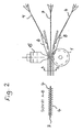
Figur 2 zeigt die Vorrichtung in Seitenansicht, wobei hier ein dreilagiger Verbund hergestellt wird. Figure 2 shows the device in side view, in which case a three-layer composite is produced.
Dabei werden von oben und unten die gewellten Vliese 4 der Walze 1 und der
Schweißvorrichtung 15 zugeführt, die dazu als kammartige Ultraschweißmaschine
(Sonotrode) ausgebildet ist. In der Mitte wird die Folienbahn 7 aus elastischem
Kunststoff zugestellt. Seitlich sind äußere Führungen 8 angedeutet. Der Schnitt
AB zeigt den entstehenden Verbund aus oberem und unterem gewellten Vlies 4
sowie der dazwischen befindlichen Folie 7.In this case, from above and below the
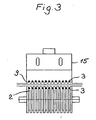
Figur 3 zeigt in Stirnansicht die obere Schweißvorrichtung die als kammartige
Ultraschallsonotrode ausgebildet ist. In vorliegendem Beispiel reichen die Fingerleisten
3 sowohl in den Grund des Kammes 9, als auch den Grund der Nuten 2
der Walze 1. Die Vlieslagen 4 sowie die Folie 7 stehen beidseitig über, die Überstände
können abgeschnitten werden. Figure 3 shows in front view of the upper welding device which is designed as a comb-like ultrasonic sonotrode. In the present example, the finger strips 3 extend both into the bottom of the comb 9, as well as the bottom of the
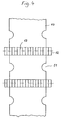
Figur 4 zeigt einen von einer Maschine geförderten Windelausschnitt 10 mit Beinausnehmungen 11. FIG. 4 shows a machine-fed diaper cut 10 with leg recesses 11.
Auf diesen Zuschnitt 10 kann das erfindungsgemäße Verbundmaterial in längsrichtung,
d. h. in Richtung der Zuschnittförderung zu Bündchen 12 zugeschnitten
und aufgeschweißt werden, wobei die Schneidrichtung quer zur Materialbahn der
Bündchen 12 erfolgt, da die Wellen 13 erfindungsgemäß ebenfalls längs zur Fördereinrichtung
des Windelzuschnitts 10 liegen. On this blank 10, the composite material according to the invention in the longitudinal direction,
d. H. cut to
- 11
- Walzeroller
- 22
- Nutengroove
- 33
- Fingerleistenfinger ridges
- 44
- Vliesfleece
- 55
- Wellewave
- 66
- StegeStege
- 77
- Foliefoil
- 88th
- Führungenguides
- 99
- KammComb
- 1010
- Windelzuschnittdiaper blank
- 1111
- BeinausnehmungenBeinausnehmungen
- 1212
- Bündchencuffs
- 1313
- Wellenwaves
- 1414
- Produktproduct
Claims (12)
Applications Claiming Priority (2)
| Application Number | Priority Date | Filing Date | Title |
|---|---|---|---|
| DE10351831 | 2003-11-06 | ||
| DE10351831A DE10351831B4 (en) | 2003-11-06 | 2003-11-06 | Process for producing multilayer material webs |
Publications (2)
| Publication Number | Publication Date |
|---|---|
| EP1529623A2 true EP1529623A2 (en) | 2005-05-11 |
| EP1529623A3 EP1529623A3 (en) | 2005-10-12 |
Family
ID=34428580
Family Applications (1)
| Application Number | Title | Priority Date | Filing Date |
|---|---|---|---|
| EP04019353A Withdrawn EP1529623A3 (en) | 2003-11-06 | 2004-08-14 | Method of making multilayered webs |
Country Status (2)
| Country | Link |
|---|---|
| EP (1) | EP1529623A3 (en) |
| DE (1) | DE10351831B4 (en) |
Cited By (4)
| Publication number | Priority date | Publication date | Assignee | Title |
|---|---|---|---|---|
| WO2006131950A1 (en) * | 2005-06-10 | 2006-12-14 | Fintex & Partners Italia S.P.A. | Method and machine for producing a composite article |
| WO2021043943A1 (en) * | 2019-09-06 | 2021-03-11 | Herrmann Ultraschalltechnik Gmbh & Co. Kg | Device and method for producing a material that is gathered or able to be gathered |
| US11597184B2 (en) | 2017-10-31 | 2023-03-07 | Kimberly-Clark Worldwide, Inc. | Elastic laminates with curved elastics and methods for manufacturing |
| US11684522B2 (en) | 2017-10-31 | 2023-06-27 | Kimberly-Clark Worldwide, Inc. | Elastic laminates with curved elastics and methods for manufacturing |
Families Citing this family (2)
| Publication number | Priority date | Publication date | Assignee | Title |
|---|---|---|---|---|
| DE102005011059B3 (en) | 2005-03-10 | 2006-08-03 | Rkw Ag Rheinische Kunststoffwerke | Production of cross elastic material track for hygiene products, comprises forming fleece materials over rollers between hook and conveyor chains, circulating the chains using ribbon and stretching the ribbon using stretching unit |
| DE102006046420A1 (en) * | 2006-09-22 | 2008-04-03 | Paul Hartmann Ag | Sanitary articles or surgical drapes or disposable surgical drapes |
Citations (12)
| Publication number | Priority date | Publication date | Assignee | Title |
|---|---|---|---|---|
| FR335445A (en) * | 1903-09-22 | 1904-01-25 | Walter Long Allen | Paper corrugating machine |
| GB199538A (en) * | 1922-04-13 | 1923-06-28 | Frederick Rippon Reynolds | Improvements in and relating to machines for the production of pleated or creased paper, fabrics and the like |
| DE506599C (en) * | 1929-11-05 | 1930-09-05 | Jacob Moll | Method and device for producing shafts in easily bendable materials |
| US2747064A (en) * | 1952-08-22 | 1956-05-22 | North American Aviation Inc | Apparatus for making corrugated core structural sheet material |
| US3725164A (en) * | 1970-06-05 | 1973-04-03 | Philips Corp | Method of bonding a leader to magnetic tape |
| EP0022896A1 (en) * | 1979-07-18 | 1981-01-28 | Walter Dr. Köcher | Composite article, method of and apparatus for producing the same |
| US4474637A (en) * | 1980-06-27 | 1984-10-02 | Otto Brand Gmbh | Labeling machine and label |
| US5451219A (en) * | 1993-07-28 | 1995-09-19 | Paragon Trade Brands, Inc. | Stretchable absorbent article |
| EP0677321A1 (en) * | 1994-04-13 | 1995-10-18 | W.L. GORE & ASSOCIATES GmbH | Hose assembly and method of making the same |
| USH1558H (en) * | 1987-06-19 | 1996-07-02 | Goulait; David J. K. | Method for manufacturing and an absorbent article having elastically extensible portions |
| WO1997028962A1 (en) * | 1996-02-10 | 1997-08-14 | Corovin Gmbh | Process for producing a multi-layer elastic surface structure and multi-layer elastic surface structure |
| US5775902A (en) * | 1994-12-27 | 1998-07-07 | Kabushiki Kaisha Matsutani Seiskusho | Root canal treatment instrument and manufacturing method for the root canal treatment instrument |
Family Cites Families (3)
| Publication number | Priority date | Publication date | Assignee | Title |
|---|---|---|---|---|
| CA1286052C (en) * | 1986-12-31 | 1991-07-16 | David P. Kielpikowski | Disposable absorbent garment having elastic outer cover and integrated absorbent insert structure |
| DE4238541C2 (en) * | 1992-11-14 | 1999-01-28 | Amoco Fabrics Zweigniederlassu | Method and device for producing an elastic, multilayer material web |
| DE10210415C1 (en) * | 2002-03-09 | 2003-09-25 | Nordenia Deutschland Gronau | Process for producing an air-permeable composite film with a textile surface, which has elastic and non-elastic areas |
-
2003
- 2003-11-06 DE DE10351831A patent/DE10351831B4/en not_active Expired - Fee Related
-
2004
- 2004-08-14 EP EP04019353A patent/EP1529623A3/en not_active Withdrawn
Patent Citations (12)
| Publication number | Priority date | Publication date | Assignee | Title |
|---|---|---|---|---|
| FR335445A (en) * | 1903-09-22 | 1904-01-25 | Walter Long Allen | Paper corrugating machine |
| GB199538A (en) * | 1922-04-13 | 1923-06-28 | Frederick Rippon Reynolds | Improvements in and relating to machines for the production of pleated or creased paper, fabrics and the like |
| DE506599C (en) * | 1929-11-05 | 1930-09-05 | Jacob Moll | Method and device for producing shafts in easily bendable materials |
| US2747064A (en) * | 1952-08-22 | 1956-05-22 | North American Aviation Inc | Apparatus for making corrugated core structural sheet material |
| US3725164A (en) * | 1970-06-05 | 1973-04-03 | Philips Corp | Method of bonding a leader to magnetic tape |
| EP0022896A1 (en) * | 1979-07-18 | 1981-01-28 | Walter Dr. Köcher | Composite article, method of and apparatus for producing the same |
| US4474637A (en) * | 1980-06-27 | 1984-10-02 | Otto Brand Gmbh | Labeling machine and label |
| USH1558H (en) * | 1987-06-19 | 1996-07-02 | Goulait; David J. K. | Method for manufacturing and an absorbent article having elastically extensible portions |
| US5451219A (en) * | 1993-07-28 | 1995-09-19 | Paragon Trade Brands, Inc. | Stretchable absorbent article |
| EP0677321A1 (en) * | 1994-04-13 | 1995-10-18 | W.L. GORE & ASSOCIATES GmbH | Hose assembly and method of making the same |
| US5775902A (en) * | 1994-12-27 | 1998-07-07 | Kabushiki Kaisha Matsutani Seiskusho | Root canal treatment instrument and manufacturing method for the root canal treatment instrument |
| WO1997028962A1 (en) * | 1996-02-10 | 1997-08-14 | Corovin Gmbh | Process for producing a multi-layer elastic surface structure and multi-layer elastic surface structure |
Cited By (5)
| Publication number | Priority date | Publication date | Assignee | Title |
|---|---|---|---|---|
| WO2006131950A1 (en) * | 2005-06-10 | 2006-12-14 | Fintex & Partners Italia S.P.A. | Method and machine for producing a composite article |
| US11597184B2 (en) | 2017-10-31 | 2023-03-07 | Kimberly-Clark Worldwide, Inc. | Elastic laminates with curved elastics and methods for manufacturing |
| US11684522B2 (en) | 2017-10-31 | 2023-06-27 | Kimberly-Clark Worldwide, Inc. | Elastic laminates with curved elastics and methods for manufacturing |
| WO2021043943A1 (en) * | 2019-09-06 | 2021-03-11 | Herrmann Ultraschalltechnik Gmbh & Co. Kg | Device and method for producing a material that is gathered or able to be gathered |
| CN114390969A (en) * | 2019-09-06 | 2022-04-22 | 海尔曼超声波技术两合有限公司 | Apparatus and method for producing aggregated or aggregatable material |
Also Published As
| Publication number | Publication date |
|---|---|
| DE10351831A1 (en) | 2005-06-16 |
| EP1529623A3 (en) | 2005-10-12 |
| DE10351831B4 (en) | 2006-02-23 |
Similar Documents
| Publication | Publication Date | Title |
|---|---|---|
| EP1736306B1 (en) | Composite fabric with inelastic and elastic regions | |
| EP2553156B1 (en) | Highly flexible absorbent laminate and method for producing same | |
| DE60006189T2 (en) | Process for producing an elastically stretchable composite film | |
| DE4238541C2 (en) | Method and device for producing an elastic, multilayer material web | |
| DE60221750T2 (en) | Stretchable composite film and method of making it with a plurality of pleats | |
| DE60006190T2 (en) | Process for producing an elastically stretchable composite film | |
| DE60208860T2 (en) | The disposable panty | |
| DE60120023T3 (en) | Elastic stretchable film and associated manufacturing method | |
| DE19806530B4 (en) | Laminate and hygiene articles made therefrom, packaging materials and tree membranes | |
| EP1302582A9 (en) | Nonwoven laminate for fastening device, process of production thereof and use | |
| DE102007018377A1 (en) | Process for producing an elastic nonwoven composite material | |
| DE60109220T2 (en) | Elastic extensible nonwoven fabric and associated manufacturing method | |
| DE19647459A1 (en) | Elastic absorbent material for sanitary wear | |
| DE212005000051U1 (en) | Hygiene products | |
| EP2566427B1 (en) | Method for producing an elastic nonwoven composite material | |
| DE10351831B4 (en) | Process for producing multilayer material webs | |
| EP1144187B1 (en) | Multi-layer composite material | |
| DE60123351T2 (en) | Process for producing an elastic composite film | |
| AT253U1 (en) | MULTILAYERED SHAPED HYGIENE PAPER | |
| EP1707351A1 (en) | Method and apparatus for fabrication of multilayer web material being elastic in cross-direction | |
| DE2035449A1 (en) | Low density plastic composite - for use as packing light weight construction, or insulating material | |
| DE60015598T2 (en) | METHOD FOR UNINTERRUPTED SEPARATION OF LEAVES FROM A TRAIN | |
| DE19647458B4 (en) | Sheets of two outer layers and one adhesive middle layer | |
| WO2021115642A1 (en) | Elastic diaper element | |
| DE10304370A1 (en) | Elastic, multi-layered material, consists of a flexible elastic carrier film made of a thermoplastic elastomer, and a fleece material attached to it |
Legal Events
| Date | Code | Title | Description |
|---|---|---|---|
| PUAI | Public reference made under article 153(3) epc to a published international application that has entered the european phase |
Free format text: ORIGINAL CODE: 0009012 |
|
| AK | Designated contracting states |
Kind code of ref document: A2 Designated state(s): AT BE BG CH CY CZ DE DK EE ES FI FR GB GR HU IE IT LI LU MC NL PL PT RO SE SI SK TR |
|
| AX | Request for extension of the european patent |
Extension state: AL HR LT LV MK |
|
| PUAL | Search report despatched |
Free format text: ORIGINAL CODE: 0009013 |
|
| AK | Designated contracting states |
Kind code of ref document: A3 Designated state(s): AT BE BG CH CY CZ DE DK EE ES FI FR GB GR HU IE IT LI LU MC NL PL PT RO SE SI SK TR |
|
| AX | Request for extension of the european patent |
Extension state: AL HR LT LV MK |
|
| RIC1 | Information provided on ipc code assigned before grant |
Ipc: 7B 29C 65/08 B Ipc: 7B 29C 53/26 B Ipc: 7B 32B 5/04 B Ipc: 7B 31F 1/22 B Ipc: 7B 32B 31/00 B Ipc: 7B 29C 65/02 A |
|
| 17P | Request for examination filed |
Effective date: 20060304 |
|
| AKX | Designation fees paid |
Designated state(s): AT BE BG CH CY CZ DE DK EE ES FI FR GB GR HU IE IT LI LU MC NL PL PT RO SE SI SK TR |
|
| 17Q | First examination report despatched |
Effective date: 20061009 |
|
| GRAP | Despatch of communication of intention to grant a patent |
Free format text: ORIGINAL CODE: EPIDOSNIGR1 |
|
| RIC1 | Information provided on ipc code assigned before grant |
Ipc: B29C 65/08 20060101ALI20070725BHEP Ipc: B29C 53/26 20060101ALI20070725BHEP Ipc: B32B 5/04 20060101ALI20070725BHEP Ipc: B31F 1/22 20060101ALI20070725BHEP Ipc: B29C 65/02 20060101AFI20070725BHEP |
|
| STAA | Information on the status of an ep patent application or granted ep patent |
Free format text: STATUS: THE APPLICATION HAS BEEN WITHDRAWN |
|
| 18W | Application withdrawn |
Effective date: 20070831 |