EP1529596A2 - Index table assembly with two bearings - Google Patents
Index table assembly with two bearings Download PDFInfo
- Publication number
- EP1529596A2 EP1529596A2 EP04025664A EP04025664A EP1529596A2 EP 1529596 A2 EP1529596 A2 EP 1529596A2 EP 04025664 A EP04025664 A EP 04025664A EP 04025664 A EP04025664 A EP 04025664A EP 1529596 A2 EP1529596 A2 EP 1529596A2
- Authority
- EP
- European Patent Office
- Prior art keywords
- rotary table
- bearing
- frame
- workpiece
- receiving surface
- Prior art date
- Legal status (The legal status is an assumption and is not a legal conclusion. Google has not performed a legal analysis and makes no representation as to the accuracy of the status listed.)
- Granted
Links
Images


Classifications
-
- B—PERFORMING OPERATIONS; TRANSPORTING
- B23—MACHINE TOOLS; METAL-WORKING NOT OTHERWISE PROVIDED FOR
- B23Q—DETAILS, COMPONENTS, OR ACCESSORIES FOR MACHINE TOOLS, e.g. ARRANGEMENTS FOR COPYING OR CONTROLLING; MACHINE TOOLS IN GENERAL CHARACTERISED BY THE CONSTRUCTION OF PARTICULAR DETAILS OR COMPONENTS; COMBINATIONS OR ASSOCIATIONS OF METAL-WORKING MACHINES, NOT DIRECTED TO A PARTICULAR RESULT
- B23Q1/00—Members which are comprised in the general build-up of a form of machine, particularly relatively large fixed members
- B23Q1/25—Movable or adjustable work or tool supports
- B23Q1/26—Movable or adjustable work or tool supports characterised by constructional features relating to the co-operation of relatively movable members; Means for preventing relative movement of such members
- B23Q1/262—Movable or adjustable work or tool supports characterised by constructional features relating to the co-operation of relatively movable members; Means for preventing relative movement of such members with means to adjust the distance between the relatively slidable members
- B23Q1/265—Movable or adjustable work or tool supports characterised by constructional features relating to the co-operation of relatively movable members; Means for preventing relative movement of such members with means to adjust the distance between the relatively slidable members between rotating members
-
- B—PERFORMING OPERATIONS; TRANSPORTING
- B23—MACHINE TOOLS; METAL-WORKING NOT OTHERWISE PROVIDED FOR
- B23Q—DETAILS, COMPONENTS, OR ACCESSORIES FOR MACHINE TOOLS, e.g. ARRANGEMENTS FOR COPYING OR CONTROLLING; MACHINE TOOLS IN GENERAL CHARACTERISED BY THE CONSTRUCTION OF PARTICULAR DETAILS OR COMPONENTS; COMBINATIONS OR ASSOCIATIONS OF METAL-WORKING MACHINES, NOT DIRECTED TO A PARTICULAR RESULT
- B23Q16/00—Equipment for precise positioning of tool or work into particular locations not otherwise provided for
- B23Q16/02—Indexing equipment
- B23Q16/022—Indexing equipment in which only the indexing movement is of importance
- B23Q16/025—Indexing equipment in which only the indexing movement is of importance by converting a continuous movement into a rotary indexing movement
-
- F—MECHANICAL ENGINEERING; LIGHTING; HEATING; WEAPONS; BLASTING
- F16—ENGINEERING ELEMENTS AND UNITS; GENERAL MEASURES FOR PRODUCING AND MAINTAINING EFFECTIVE FUNCTIONING OF MACHINES OR INSTALLATIONS; THERMAL INSULATION IN GENERAL
- F16C—SHAFTS; FLEXIBLE SHAFTS; ELEMENTS OR CRANKSHAFT MECHANISMS; ROTARY BODIES OTHER THAN GEARING ELEMENTS; BEARINGS
- F16C19/00—Bearings with rolling contact, for exclusively rotary movement
- F16C19/54—Systems consisting of a plurality of bearings with rolling friction
- F16C19/545—Systems comprising at least one rolling bearing for radial load in combination with at least one rolling bearing for axial load
-
- F—MECHANICAL ENGINEERING; LIGHTING; HEATING; WEAPONS; BLASTING
- F16—ENGINEERING ELEMENTS AND UNITS; GENERAL MEASURES FOR PRODUCING AND MAINTAINING EFFECTIVE FUNCTIONING OF MACHINES OR INSTALLATIONS; THERMAL INSULATION IN GENERAL
- F16C—SHAFTS; FLEXIBLE SHAFTS; ELEMENTS OR CRANKSHAFT MECHANISMS; ROTARY BODIES OTHER THAN GEARING ELEMENTS; BEARINGS
- F16C2322/00—Apparatus used in shaping articles
- F16C2322/39—General buildup of machine tools, e.g. spindles, slides, actuators
-
- Y—GENERAL TAGGING OF NEW TECHNOLOGICAL DEVELOPMENTS; GENERAL TAGGING OF CROSS-SECTIONAL TECHNOLOGIES SPANNING OVER SEVERAL SECTIONS OF THE IPC; TECHNICAL SUBJECTS COVERED BY FORMER USPC CROSS-REFERENCE ART COLLECTIONS [XRACs] AND DIGESTS
- Y10—TECHNICAL SUBJECTS COVERED BY FORMER USPC
- Y10T—TECHNICAL SUBJECTS COVERED BY FORMER US CLASSIFICATION
- Y10T74/00—Machine element or mechanism
- Y10T74/14—Rotary member or shaft indexing, e.g., tool or work turret
-
- Y—GENERAL TAGGING OF NEW TECHNOLOGICAL DEVELOPMENTS; GENERAL TAGGING OF CROSS-SECTIONAL TECHNOLOGIES SPANNING OVER SEVERAL SECTIONS OF THE IPC; TECHNICAL SUBJECTS COVERED BY FORMER USPC CROSS-REFERENCE ART COLLECTIONS [XRACs] AND DIGESTS
- Y10—TECHNICAL SUBJECTS COVERED BY FORMER USPC
- Y10T—TECHNICAL SUBJECTS COVERED BY FORMER US CLASSIFICATION
- Y10T74/00—Machine element or mechanism
- Y10T74/19—Gearing
- Y10T74/19642—Directly cooperating gears
- Y10T74/19698—Spiral
- Y10T74/19828—Worm
Definitions
- the present invention relates to index table assemblies.
- the first thrust bearing receives a force applied in a direction from the workpiece-receiving surface of the rotary table toward the frame along the rotational axis
- the second thrust bearing receives a force applied in a direction opposite to the direction from the workpiece-receiving surface of the rotary table toward the frame along the rotational axis.
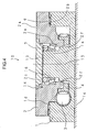
- the rotary table 2 has a workpiece-receiving surface 2a which is perpendicular to a rotational axis 15 and to which a process table, a jig, and the like (not shown) are attached, a surface 2b on the side opposite to the workpiece-receiving surface 2a, and a through hole 2c extending along the rotational axis 15.
- the through hole 2c is formed at a rotational center of the rotary table 2, and has a step portion 2d extending toward the rotational center, that is, toward the rotational axis 15 in the middle of the through hole 2c.
- the step portion 2d is formed along the entire circumference of the through hole 2c, and has a step surface 2e on the same side as the workpiece-receiving surface 2a and a step surface 2f on the side opposite to the workpiece-receiving surface 2a.
- the bearing support 7 Since the bearing support 7 is detachably attached to the shaft portion 1a which extends through the step portion 2d, the end surface 1b projects from the step surface 2e of the step portion 2d. Accordingly, the relative position between the bearing support 7 and the shaft portion 1a is adjusted in a region outside the step portion 2d, and the preload applied to the thrust bearings 9 and 10 is easily and accurately adjusted using the shim 12.
Landscapes
- Engineering & Computer Science (AREA)
- Mechanical Engineering (AREA)
- General Engineering & Computer Science (AREA)
- Machine Tool Units (AREA)
- Grinding Of Cylindrical And Plane Surfaces (AREA)
Abstract
Description
and
Claims (7)
- An index table assembly (50, 60, 70, 80) including a rotary table (2), a frame (1) separated from the rotary table (2) in the direction of a rotational axis (15) of the rotary table (2), and a first bearing (9) and a second bearing (10, 16) disposed between the rotary table (2) and the frame (1), characterized in that:the rotary table (2) has a workpiece-receiving surface (2a) on one side and a through hole (2c) at a rotational center of the rotary table (2), the through hole (2c) having a step portion (2d) extending toward the rotational center in the middle of the through hole (2c);the frame (1) includes a shaft portion (1a) extending through the step portion (2d) and a bearing support (7) detachably attached to the shaft portion (1a), the bearing support (7) facing a surface (2e) of the step portion (2d) on the same side as the workpiece-receiving surface (2a) of the rotary table (2); andthe first bearing (9) is positioned between a surface (2b) of the rotary table (2) on the side opposite to the workpiece-receiving surface (2a) and the frame (1) and the second bearing (10, 16) is positioned between the surface (2e) of the step portion (2d) on the same side as the workpiece-receiving surface (2a) and the bearing support (7).
- An index table assembly (50, 60, 70, 80) according to Claim 1, wherein the first bearing (9) has a larger diameter than the second bearing (10, 16).
- An index table assembly (50, 60, 70, 80) according to one of Claims 1 and 2, wherein the bearing support (7) is detachably attached to the shaft portion (1a) at an end of the shaft portion (1a).
- An index table assembly (50, 60, 70, 80) according to one of Claims 1 to 3, wherein a portion of the rotary table (2) including the workpiece-receiving surface (2a) and the step portion (2d) consist of a single material.
- An index table assembly (50, 60, 70, 80) according to one of Claims 1 to 4, wherein the surfaces between which the first bearing (9) and the second bearing (10, 16) are disposed are perpendicular to the rotational axis (15) of the rotary table (2).
- An index table assembly (50, 60, 80) according to one of Claims 1 to 5, wherein both of the first bearing (9) and the second bearing (10) are thrust bearings.
- An index table assembly (70) according to one of Claims 1 to 5, wherein the second bearing (16) is one of a tapered roller bearing and an angular bearing, and the surface (2e) of the step portion (2d) on the same side as the workpiece-receiving surface (2a) and the bearing support (7) face each other such that the surface (2e) of the step portion (2d) on the same side as the workpiece-receiving surface (2a) and the bearing support (7) are shifted relative to each other in the radial direction of the rotary table (2).
Applications Claiming Priority (2)
| Application Number | Priority Date | Filing Date | Title |
|---|---|---|---|
| JP2003378894 | 2003-11-07 | ||
| JP2003378894A JP4320241B2 (en) | 2003-11-07 | 2003-11-07 | Index table |
Publications (3)
| Publication Number | Publication Date |
|---|---|
| EP1529596A2 true EP1529596A2 (en) | 2005-05-11 |
| EP1529596A3 EP1529596A3 (en) | 2006-02-15 |
| EP1529596B1 EP1529596B1 (en) | 2007-08-29 |
Family
ID=34431363
Family Applications (1)
| Application Number | Title | Priority Date | Filing Date |
|---|---|---|---|
| EP04025664A Expired - Lifetime EP1529596B1 (en) | 2003-11-07 | 2004-10-28 | Index table assembly with two bearings |
Country Status (5)
| Country | Link |
|---|---|
| US (1) | US7530293B2 (en) |
| EP (1) | EP1529596B1 (en) |
| JP (1) | JP4320241B2 (en) |
| CN (1) | CN100443258C (en) |
| DE (1) | DE602004008552T2 (en) |
Cited By (4)
| Publication number | Priority date | Publication date | Assignee | Title |
|---|---|---|---|---|
| DE102005024004A1 (en) * | 2005-05-25 | 2006-12-07 | Schaeffler Kg | Rotary bearing device, in particular for a rotatable rotary table of a machine tool |
| KR20200119168A (en) * | 2019-04-09 | 2020-10-19 | 두산공작기계 주식회사 | Table of machine tool |
| KR20210125705A (en) * | 2020-04-09 | 2021-10-19 | 두산공작기계 주식회사 | Bed connection structure of machine tools |
| EP4091766A1 (en) * | 2021-05-19 | 2022-11-23 | Tsudakoma Kogyo Kabushiki Kaisha | Rotary table device |
Families Citing this family (17)
| Publication number | Priority date | Publication date | Assignee | Title |
|---|---|---|---|---|
| TW200821083A (en) * | 2006-10-26 | 2008-05-16 | Tsudakoma Ind Co Ltd | Angle indexing device for machine tool |
| JP4971763B2 (en) * | 2006-11-29 | 2012-07-11 | 津田駒工業株式会社 | Drive motor drive control method in rotary indexing device for machine tool |
| JP5192278B2 (en) * | 2008-04-21 | 2013-05-08 | 津田駒工業株式会社 | Index table |
| CN101966615B (en) * | 2010-09-30 | 2012-01-04 | 苏州电加工机床研究所有限公司 | External rotary index table for electrical process machine |
| KR101608322B1 (en) * | 2014-11-12 | 2016-04-05 | (주)새한나노텍 | Index table with backlash preventable structure |
| JP5960370B1 (en) * | 2015-02-24 | 2016-08-02 | ファナック株式会社 | Rotary table device |
| CN104776299B (en) * | 2015-04-17 | 2016-11-23 | 合肥耀辉太阳能热力工程科技有限公司 | A kind of by pivoting support with the actuating device of reducer group |
| DE102015110779A1 (en) * | 2015-07-03 | 2017-01-05 | Franz Kessler Gmbh | Turntable for a machine tool |
| DE102016112025A1 (en) | 2015-07-03 | 2017-01-05 | Franz Kessler Gmbh | Turntable for a machine tool |
| JP6370767B2 (en) * | 2015-11-25 | 2018-08-08 | ファナック株式会社 | Rotary table device for electric discharge machine |
| US20170326702A1 (en) * | 2016-05-12 | 2017-11-16 | Tsudakoma Kogyo Kabushiki Kaisha | Rotary table device for machine tool |
| CN106003188A (en) * | 2016-07-20 | 2016-10-12 | 芜湖昊轩环保新材料有限公司 | Plate cutting device |
| CN108044368A (en) * | 2018-01-16 | 2018-05-18 | 江苏杰尔科技股份有限公司 | Large-scale simple fan centre circle circumference equal-dividing hole processing tool |
| KR102836005B1 (en) * | 2019-11-08 | 2025-07-18 | 가부시끼가이샤 산쿄 세이사쿠쇼 | Rotary positioning device |
| JP7415583B2 (en) * | 2020-01-23 | 2024-01-17 | 株式会社ジェイテクト | rotary table device |
| JP7415584B2 (en) * | 2020-01-23 | 2024-01-17 | 株式会社ジェイテクト | rotary table device |
| CN112658783A (en) * | 2021-01-07 | 2021-04-16 | 湖南工匠实创智能机器有限责任公司 | Direct-drive precise rotary table device |
Family Cites Families (13)
| Publication number | Priority date | Publication date | Assignee | Title |
|---|---|---|---|---|
| US3941014A (en) * | 1975-01-20 | 1976-03-02 | Erickson Tool Company | Precision heavy duty indexer |
| JPS5384279A (en) * | 1976-12-29 | 1978-07-25 | Fanuc Ltd | Indexing table |
| US4380939A (en) * | 1980-07-01 | 1983-04-26 | Cameron Iron Works, Inc. | Rotary indexing table |
| CN85106747A (en) * | 1985-09-05 | 1987-03-25 | 卡尼特雷克公司 | The rotary shuttle of lathe |
| CN2054392U (en) * | 1989-01-31 | 1990-03-14 | 山东菏泽油泵油嘴厂 | Gyratory conversion device for machine tool |
| JPH0750133Y2 (en) * | 1989-08-01 | 1995-11-15 | 株式会社森精機製作所 | Indexing device for index table of machine tool |
| US5201249A (en) * | 1992-02-25 | 1993-04-13 | Progressive Blasting Systems | Multi-purpose indexing turntable |
| JP2930889B2 (en) | 1995-05-11 | 1999-08-09 | 株式会社日研工作所 | Rotary table |
| US5735514A (en) * | 1996-09-03 | 1998-04-07 | Chick Machine Tool, Inc. | Indexing apparatus |
| JPH1177489A (en) * | 1997-09-01 | 1999-03-23 | Mori Seiki Co Ltd | Indexing mechanism for machine tools |
| JP2002210634A (en) * | 2001-01-18 | 2002-07-30 | Tsudakoma Corp | Multi-axis index table |
| DE60112128T2 (en) * | 2001-04-30 | 2006-04-20 | Duplomatic Automazione S.P.A., Busto Arsizio | MULTIFUNCTIONAL POSITION MECHANISM AS A CARRIER FOR TOOL HOLDER |
| JP4727917B2 (en) * | 2003-11-06 | 2011-07-20 | 津田駒工業株式会社 | Index table |
-
2003
- 2003-11-07 JP JP2003378894A patent/JP4320241B2/en not_active Expired - Fee Related
-
2004
- 2004-07-13 US US10/889,097 patent/US7530293B2/en active Active
- 2004-10-28 EP EP04025664A patent/EP1529596B1/en not_active Expired - Lifetime
- 2004-10-28 DE DE602004008552T patent/DE602004008552T2/en not_active Expired - Lifetime
- 2004-11-05 CN CNB2004100922689A patent/CN100443258C/en not_active Expired - Fee Related
Cited By (5)
| Publication number | Priority date | Publication date | Assignee | Title |
|---|---|---|---|---|
| DE102005024004A1 (en) * | 2005-05-25 | 2006-12-07 | Schaeffler Kg | Rotary bearing device, in particular for a rotatable rotary table of a machine tool |
| KR20200119168A (en) * | 2019-04-09 | 2020-10-19 | 두산공작기계 주식회사 | Table of machine tool |
| KR20210125705A (en) * | 2020-04-09 | 2021-10-19 | 두산공작기계 주식회사 | Bed connection structure of machine tools |
| EP4091766A1 (en) * | 2021-05-19 | 2022-11-23 | Tsudakoma Kogyo Kabushiki Kaisha | Rotary table device |
| US11986915B2 (en) | 2021-05-19 | 2024-05-21 | Tsudakoma Kogyo Kabushiki Kaisha | Rotary table device |
Also Published As
| Publication number | Publication date |
|---|---|
| EP1529596B1 (en) | 2007-08-29 |
| US7530293B2 (en) | 2009-05-12 |
| CN1613604A (en) | 2005-05-11 |
| US20050097976A1 (en) | 2005-05-12 |
| DE602004008552T2 (en) | 2008-05-21 |
| JP4320241B2 (en) | 2009-08-26 |
| JP2005138243A (en) | 2005-06-02 |
| DE602004008552D1 (en) | 2007-10-11 |
| CN100443258C (en) | 2008-12-17 |
| EP1529596A3 (en) | 2006-02-15 |
Similar Documents
| Publication | Publication Date | Title |
|---|---|---|
| EP1529596B1 (en) | Index table assembly with two bearings | |
| EP2563639B1 (en) | Apparatus for final finishing a wheel hub of a knuckle assembly and related method | |
| US7942080B2 (en) | Index table assembly | |
| US5983482A (en) | Method for processing shaft for hub unit and method for producing the shaft | |
| US6158124A (en) | Preloading & machining mounted brake disc | |
| US5597965A (en) | Method and apparatus for measuring the preload gap of a double row rolling bearing | |
| US5937499A (en) | Machining brake disc without moment load on bearing | |
| EP1201353B1 (en) | Rotating table apparatus | |
| EP1196261B1 (en) | A method of machining a hub bearing unit for a wheel of a motor vehicle | |
| US20010036327A1 (en) | Dynamic pressure bearing device and method of manufacturing the same | |
| US6099167A (en) | Wheel bearing | |
| EP1752242B1 (en) | Processing method for brake rotor-equiped wheel bearing devices | |
| CN114571261A (en) | Anti-backlash numerical control turntable and control method thereof | |
| US20070114863A1 (en) | Brushless motor | |
| EP0743118B1 (en) | High-precision revolving centre | |
| EP0741631B1 (en) | Positive radial location of wheels on spindles | |
| IE50904B1 (en) | Compliant rotary meber and friction drive | |
| JP2003340705A (en) | Grinder | |
| JP4848693B2 (en) | Polishing jig for rolling mill backup roll bearing | |
| KR100345180B1 (en) | Connecting structure for coupling a pully to a spindle in a main shaft unit of automatic lathe | |
| JP2564579Y2 (en) | Spacer for rolling bearing | |
| KR100289564B1 (en) | Magnetic Disc Drive Motor | |
| JPH07328919A (en) | Grindstone holding structure | |
| JP2001121510A (en) | Tightening structure of rotary tool | |
| JP2000192977A (en) | Manufacturing method of bearing unit |
Legal Events
| Date | Code | Title | Description |
|---|---|---|---|
| PUAI | Public reference made under article 153(3) epc to a published international application that has entered the european phase |
Free format text: ORIGINAL CODE: 0009012 |
|
| AK | Designated contracting states |
Kind code of ref document: A2 Designated state(s): AT BE BG CH CY CZ DE DK EE ES FI FR GB GR HU IE IT LI LU MC NL PL PT RO SE SI SK TR |
|
| AX | Request for extension of the european patent |
Extension state: AL HR LT LV MK |
|
| PUAL | Search report despatched |
Free format text: ORIGINAL CODE: 0009013 |
|
| AK | Designated contracting states |
Kind code of ref document: A3 Designated state(s): AT BE BG CH CY CZ DE DK EE ES FI FR GB GR HU IE IT LI LU MC NL PL PT RO SE SI SK TR |
|
| AX | Request for extension of the european patent |
Extension state: AL HR LT LV MK |
|
| RIC1 | Information provided on ipc code assigned before grant |
Ipc: B23Q 1/26 20060101AFI20051223BHEP Ipc: B23Q 16/02 20060101ALI20051223BHEP |
|
| 17P | Request for examination filed |
Effective date: 20060331 |
|
| 17Q | First examination report despatched |
Effective date: 20060719 |
|
| AKX | Designation fees paid |
Designated state(s): CH DE FR IT LI |
|
| GRAP | Despatch of communication of intention to grant a patent |
Free format text: ORIGINAL CODE: EPIDOSNIGR1 |
|
| GRAS | Grant fee paid |
Free format text: ORIGINAL CODE: EPIDOSNIGR3 |
|
| GRAA | (expected) grant |
Free format text: ORIGINAL CODE: 0009210 |
|
| AK | Designated contracting states |
Kind code of ref document: B1 Designated state(s): CH DE FR IT LI |
|
| REG | Reference to a national code |
Ref country code: CH Ref legal event code: EP |
|
| REF | Corresponds to: |
Ref document number: 602004008552 Country of ref document: DE Date of ref document: 20071011 Kind code of ref document: P |
|
| REG | Reference to a national code |
Ref country code: CH Ref legal event code: NV Representative=s name: E. BLUM & CO. AG PATENT- UND MARKENANWAELTE VSP |
|
| ET | Fr: translation filed | ||
| PLBE | No opposition filed within time limit |
Free format text: ORIGINAL CODE: 0009261 |
|
| STAA | Information on the status of an ep patent application or granted ep patent |
Free format text: STATUS: NO OPPOSITION FILED WITHIN TIME LIMIT |
|
| 26N | No opposition filed |
Effective date: 20080530 |
|
| PGFP | Annual fee paid to national office [announced via postgrant information from national office to epo] |
Ref country code: FR Payment date: 20121018 Year of fee payment: 9 |
|
| REG | Reference to a national code |
Ref country code: FR Ref legal event code: ST Effective date: 20140630 |
|
| PG25 | Lapsed in a contracting state [announced via postgrant information from national office to epo] |
Ref country code: FR Free format text: LAPSE BECAUSE OF NON-PAYMENT OF DUE FEES Effective date: 20131031 |
|
| PGFP | Annual fee paid to national office [announced via postgrant information from national office to epo] |
Ref country code: IT Payment date: 20210910 Year of fee payment: 18 Ref country code: CH Payment date: 20210928 Year of fee payment: 18 |
|
| PGFP | Annual fee paid to national office [announced via postgrant information from national office to epo] |
Ref country code: DE Payment date: 20210914 Year of fee payment: 18 |
|
| REG | Reference to a national code |
Ref country code: DE Ref legal event code: R119 Ref document number: 602004008552 Country of ref document: DE |
|
| REG | Reference to a national code |
Ref country code: CH Ref legal event code: PL |
|
| PG25 | Lapsed in a contracting state [announced via postgrant information from national office to epo] |
Ref country code: LI Free format text: LAPSE BECAUSE OF NON-PAYMENT OF DUE FEES Effective date: 20221031 Ref country code: DE Free format text: LAPSE BECAUSE OF NON-PAYMENT OF DUE FEES Effective date: 20230503 Ref country code: CH Free format text: LAPSE BECAUSE OF NON-PAYMENT OF DUE FEES Effective date: 20221031 |
|
| PG25 | Lapsed in a contracting state [announced via postgrant information from national office to epo] |
Ref country code: IT Free format text: LAPSE BECAUSE OF NON-PAYMENT OF DUE FEES Effective date: 20221028 |