EP1529554A1 - Radioaktive Strahlungsquelle zur ophtalmischen Brachytherapie - Google Patents
Radioaktive Strahlungsquelle zur ophtalmischen Brachytherapie Download PDFInfo
- Publication number
- EP1529554A1 EP1529554A1 EP03025416A EP03025416A EP1529554A1 EP 1529554 A1 EP1529554 A1 EP 1529554A1 EP 03025416 A EP03025416 A EP 03025416A EP 03025416 A EP03025416 A EP 03025416A EP 1529554 A1 EP1529554 A1 EP 1529554A1
- Authority
- EP
- European Patent Office
- Prior art keywords
- radiation
- emitting element
- containment
- shielding
- radiation source
- Prior art date
- Legal status (The legal status is an assumption and is not a legal conclusion. Google has not performed a legal analysis and makes no representation as to the accuracy of the status listed.)
- Granted
Links
- 230000005855 radiation Effects 0.000 title claims abstract description 233
- 238000002725 brachytherapy Methods 0.000 title claims abstract description 13
- 230000002285 radioactive effect Effects 0.000 title claims abstract description 13
- 230000007704 transition Effects 0.000 claims abstract description 43
- 239000000463 material Substances 0.000 claims description 56
- 239000002775 capsule Substances 0.000 claims description 20
- 239000000203 mixture Substances 0.000 claims description 14
- VWQVUPCCIRVNHF-OUBTZVSYSA-N Yttrium-90 Chemical compound [90Y] VWQVUPCCIRVNHF-OUBTZVSYSA-N 0.000 claims description 10
- 229910045601 alloy Inorganic materials 0.000 claims description 8
- 239000000956 alloy Substances 0.000 claims description 8
- 229910052742 iron Inorganic materials 0.000 claims description 7
- 239000004033 plastic Substances 0.000 claims description 7
- 230000000694 effects Effects 0.000 claims description 6
- 239000011159 matrix material Substances 0.000 claims description 6
- 239000007769 metal material Substances 0.000 claims description 6
- 239000010935 stainless steel Substances 0.000 claims description 6
- 229910001220 stainless steel Inorganic materials 0.000 claims description 6
- 239000002131 composite material Substances 0.000 claims description 5
- 150000001875 compounds Chemical class 0.000 claims description 5
- 229910052751 metal Inorganic materials 0.000 claims description 5
- 239000002184 metal Substances 0.000 claims description 5
- 229910052709 silver Inorganic materials 0.000 claims description 5
- 229910052782 aluminium Inorganic materials 0.000 claims description 4
- 239000000919 ceramic Substances 0.000 claims description 4
- 229910052737 gold Inorganic materials 0.000 claims description 4
- 229910052745 lead Inorganic materials 0.000 claims description 4
- 150000002739 metals Chemical class 0.000 claims description 4
- 229910052763 palladium Inorganic materials 0.000 claims description 4
- 229910052721 tungsten Inorganic materials 0.000 claims description 4
- 229910052759 nickel Inorganic materials 0.000 claims description 3
- 229910052697 platinum Inorganic materials 0.000 claims description 3
- HWLDNSXPUQTBOD-UHFFFAOYSA-N platinum-iridium alloy Chemical class [Ir].[Pt] HWLDNSXPUQTBOD-UHFFFAOYSA-N 0.000 claims description 3
- 229910052719 titanium Inorganic materials 0.000 claims description 3
- 229910052777 Praseodymium Inorganic materials 0.000 claims description 2
- 229910052776 Thorium Inorganic materials 0.000 claims description 2
- 229910001069 Ti alloy Inorganic materials 0.000 claims description 2
- 229910052769 Ytterbium Inorganic materials 0.000 claims description 2
- 229910052797 bismuth Inorganic materials 0.000 claims description 2
- 229910052793 cadmium Inorganic materials 0.000 claims description 2
- 229910052802 copper Inorganic materials 0.000 claims description 2
- 229910052738 indium Inorganic materials 0.000 claims description 2
- 229910052741 iridium Inorganic materials 0.000 claims description 2
- 229910052749 magnesium Inorganic materials 0.000 claims description 2
- 229910052748 manganese Inorganic materials 0.000 claims description 2
- 229910052750 molybdenum Inorganic materials 0.000 claims description 2
- 229910052758 niobium Inorganic materials 0.000 claims description 2
- 239000002245 particle Substances 0.000 claims description 2
- 229910052702 rhenium Inorganic materials 0.000 claims description 2
- 229910052703 rhodium Inorganic materials 0.000 claims description 2
- 229910052710 silicon Inorganic materials 0.000 claims description 2
- 229910052715 tantalum Inorganic materials 0.000 claims description 2
- 229910052718 tin Inorganic materials 0.000 claims description 2
- 229910052720 vanadium Inorganic materials 0.000 claims description 2
- 229910052727 yttrium Inorganic materials 0.000 claims description 2
- 229910052725 zinc Inorganic materials 0.000 claims description 2
- 229910052726 zirconium Inorganic materials 0.000 claims description 2
- 150000003839 salts Chemical class 0.000 claims 1
- 206010025421 Macule Diseases 0.000 abstract description 12
- 230000007850 degeneration Effects 0.000 abstract description 7
- XEEYBQQBJWHFJM-UHFFFAOYSA-N Iron Chemical compound [Fe] XEEYBQQBJWHFJM-UHFFFAOYSA-N 0.000 description 10
- 238000000034 method Methods 0.000 description 5
- 230000006378 damage Effects 0.000 description 4
- 210000001525 retina Anatomy 0.000 description 4
- 239000010936 titanium Substances 0.000 description 4
- 206010028980 Neoplasm Diseases 0.000 description 3
- 238000013459 approach Methods 0.000 description 3
- 238000003780 insertion Methods 0.000 description 3
- 230000037431 insertion Effects 0.000 description 3
- 239000003550 marker Substances 0.000 description 3
- 150000004767 nitrides Chemical class 0.000 description 3
- 239000012857 radioactive material Substances 0.000 description 3
- 238000001959 radiotherapy Methods 0.000 description 3
- 239000007787 solid Substances 0.000 description 3
- 238000001356 surgical procedure Methods 0.000 description 3
- 238000003466 welding Methods 0.000 description 3
- 239000000560 biocompatible material Substances 0.000 description 2
- 230000001678 irradiating effect Effects 0.000 description 2
- 238000002386 leaching Methods 0.000 description 2
- 230000003902 lesion Effects 0.000 description 2
- 150000001247 metal acetylides Chemical class 0.000 description 2
- 238000007789 sealing Methods 0.000 description 2
- RTAQQCXQSZGOHL-UHFFFAOYSA-N Titanium Chemical compound [Ti] RTAQQCXQSZGOHL-UHFFFAOYSA-N 0.000 description 1
- NIXOWILDQLNWCW-UHFFFAOYSA-N acrylic acid group Chemical group C(C=C)(=O)O NIXOWILDQLNWCW-UHFFFAOYSA-N 0.000 description 1
- 239000000853 adhesive Substances 0.000 description 1
- 230000001070 adhesive effect Effects 0.000 description 1
- XAGFODPZIPBFFR-UHFFFAOYSA-N aluminium Chemical compound [Al] XAGFODPZIPBFFR-UHFFFAOYSA-N 0.000 description 1
- 230000002238 attenuated effect Effects 0.000 description 1
- 239000012620 biological material Substances 0.000 description 1
- 210000001124 body fluid Anatomy 0.000 description 1
- 239000010839 body fluid Substances 0.000 description 1
- 210000005252 bulbus oculi Anatomy 0.000 description 1
- 230000003247 decreasing effect Effects 0.000 description 1
- 201000010099 disease Diseases 0.000 description 1
- 208000037265 diseases, disorders, signs and symptoms Diseases 0.000 description 1
- 238000005516 engineering process Methods 0.000 description 1
- 239000003822 epoxy resin Substances 0.000 description 1
- 239000012530 fluid Substances 0.000 description 1
- 230000009545 invasion Effects 0.000 description 1
- 238000005468 ion implantation Methods 0.000 description 1
- 230000033001 locomotion Effects 0.000 description 1
- 238000012544 monitoring process Methods 0.000 description 1
- 230000009972 noncorrosive effect Effects 0.000 description 1
- 229920000647 polyepoxide Polymers 0.000 description 1
- 229920000642 polymer Polymers 0.000 description 1
- 239000000523 sample Substances 0.000 description 1
- 239000004332 silver Substances 0.000 description 1
- 238000004544 sputter deposition Methods 0.000 description 1
- 230000001225 therapeutic effect Effects 0.000 description 1
- 238000002560 therapeutic procedure Methods 0.000 description 1
- 239000010409 thin film Substances 0.000 description 1
- 239000011800 void material Substances 0.000 description 1
Images


Classifications
-
- A—HUMAN NECESSITIES
- A61—MEDICAL OR VETERINARY SCIENCE; HYGIENE
- A61N—ELECTROTHERAPY; MAGNETOTHERAPY; RADIATION THERAPY; ULTRASOUND THERAPY
- A61N5/00—Radiation therapy
- A61N5/10—X-ray therapy; Gamma-ray therapy; Particle-irradiation therapy
- A61N5/1001—X-ray therapy; Gamma-ray therapy; Particle-irradiation therapy using radiation sources introduced into or applied onto the body; brachytherapy
- A61N5/1014—Intracavitary radiation therapy
- A61N5/1017—Treatment of the eye, e.g. for "macular degeneration"
-
- A—HUMAN NECESSITIES
- A61—MEDICAL OR VETERINARY SCIENCE; HYGIENE
- A61N—ELECTROTHERAPY; MAGNETOTHERAPY; RADIATION THERAPY; ULTRASOUND THERAPY
- A61N5/00—Radiation therapy
- A61N5/10—X-ray therapy; Gamma-ray therapy; Particle-irradiation therapy
- A61N5/1001—X-ray therapy; Gamma-ray therapy; Particle-irradiation therapy using radiation sources introduced into or applied onto the body; brachytherapy
- A61N5/1002—Intraluminal radiation therapy
- A61N2005/1005—Intraluminal radiation therapy with asymmetrical radiation pattern
-
- A—HUMAN NECESSITIES
- A61—MEDICAL OR VETERINARY SCIENCE; HYGIENE
- A61N—ELECTROTHERAPY; MAGNETOTHERAPY; RADIATION THERAPY; ULTRASOUND THERAPY
- A61N5/00—Radiation therapy
- A61N5/10—X-ray therapy; Gamma-ray therapy; Particle-irradiation therapy
- A61N5/1001—X-ray therapy; Gamma-ray therapy; Particle-irradiation therapy using radiation sources introduced into or applied onto the body; brachytherapy
- A61N2005/1019—Sources therefor
-
- A—HUMAN NECESSITIES
- A61—MEDICAL OR VETERINARY SCIENCE; HYGIENE
- A61N—ELECTROTHERAPY; MAGNETOTHERAPY; RADIATION THERAPY; ULTRASOUND THERAPY
- A61N5/00—Radiation therapy
- A61N5/10—X-ray therapy; Gamma-ray therapy; Particle-irradiation therapy
- A61N2005/1092—Details
- A61N2005/1094—Shielding, protecting against radiation
Definitions
- the present invention relates to a radioactive radiation source for brachytherapy, and especially a radiation source for localized delivery of radiation in surgical procedures, particularly ophthalmic procedures.
- brachytherapy for treatment of localized lesions, especially tumors and macula degeneration employs radioactive sealed radiation sources.
- sealed means that radioisotopes incorporated into a device are integral with the device and cannot be dislodged or released from the host material of the device in the environment of usage.
- a typical sealed radiation source includes a radiation source encapsulated within an impermeable, biocompatible capsule material, for example titanium, which is designed to prevent any leaching or a release of the radioisotope.
- the source is typically about 4.5 mm long and has a diameter of about 0.8 mm and is implanted individually at a treatment side within or around a lesion by using hollow delivery needles. These sources suffer from the disadvantage that they provide a homogeneous coaxial radiation pattern over their entire circumference resulting in undesirable irradiation of surrounding healthy tissue.
- hemispherical ophthalmic plaques are used as sources, incorporating a radioactive material are sewn directly to the eyeball to provide a radiation dose to the intraocular tumor on the concave side of the plaque.
- These plaques comprise typically a thin film of Ru-106 encapsulated within two sheets of silver, the sheet on the concave side being approximately 0.1 mm thick and the sheet on the convex side being approximately 0.7 mm thick. Accordingly, these sources provide partial shielding of healthy tissue. Greater sheet thickness provides additional radiation shielding but adds to the thickness of the plaque, which increases discomfort to the patient.
- US patent 6 030 333 discloses an implantable radiotherapy device or radiation source for delivering a predetermined dose of radiation in a predetermined pattern, which device includes a biocompatible template and one or more radiation sources which are incorporated directly into at least a portion of the template preferably by ion implantation methods.
- the emitted radiation pattern and dose is exclusively determined by the pattern of implanting the radiation emitting material into the device or carrier.
- US patent 6 443 881 discloses a method and an apparatus for use in ocular or ophthalmic brachytherapy.
- the device comprises a handle, an applicator coupled with said handle, and adapted to receive a source of radiation.
- the typically concave shaped applicator is movable between a radiation shielding position and a position wherein radiation is allowed to reach the diseased area.
- a shield receives the applicator so as to shield the radiation source during insertion and positioning proximal to the treatment side.
- Some sort of shielding may further be provided to prevent emission of radiation in direction towards other tissues than the retina to be treated.
- the radiation In the treatment position, the radiation is directed outwardly through an open area opposing the application site.
- a comparable device is disclosed in US-B1-6 285 735.
- This document discloses an applicator system for applying a dose of x-ray radiation across a predefined contour of a body to treat a predefined volume of tissue.
- the adapter includes an applicator endcap including a substantially planar or convex treatment surface for engating and conforming a tissue cavity to the desired shape in order to permit the volume of adjacent tissue to be treated with a predefined dose of radiation.
- the applicator may include a shank having a substantially conical void region to form the punctual radiation beam.
- the shank may further include an endcap of an appropriate form to facilitate the application of radiation to a surface area and to modulate the emitted radiation uniformly over the surface.
- the endcap is preferably formed from a biocompatible acrylic material and fixed to the shank using an epoxy resin.
- the endcap is directly in contact with the tissue to be treated and is not in contact with the radiation source or probe as defined in the document. Just in contrast, the endcap forms part of the applicator device, not the radiation source itself.
- US 2002/01 15 902 discloses a surgical device for localized delivery of beta-radiation in surgical procedures, particularly ophthalmic procedures, which device includes a canula with a beta-therapy emitting material at the distal end of the canula.
- the device may further comprise a shield at the distal end of the canula for shielding the beta-radiotherapy emitting material.
- This shield at the distal end of the canula may be a thin wall of metal such as stainless steel, or maybe a thin wall of polymer, plastic or similar material.
- the shield may be retractable to expose the beta-radiotherapy emitting material for treatment.
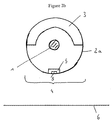
- a radioactive radiation source for brachytherapy having an elongated radiation emitting element (1) within an elongated means for containment (2) such that the longitudinal axis of the radiation emitting element and the longitudinal axis of said means for containment are aligned, said means for containment comprising a shielding section (3) and a radiation transition section (4),
- the shielding material (5) may be adapted to attenuation of the radiation by varying its thickness, density and/or composition. In general, said shielding material may be adapted by varying its shielding properties.
- the means for containment (2) comprises a first capsule (2a) in form of a first sealed metallic cylinder having endplugs.
- a second metallic cylinder is provided within said first cylinder.
- the first or upper half circle of the second cylinder within the first cylinder forms a shielding section (3) and the second half circle forms a radiation transition section (4).
- the shielding material (5) in the radiation transition section (4) is adapted by varying the wall thickness of the second cylinder.
- recesses (7) are provided parallel to a central bar forming cross bridge (8).
- the 4 recesses on each side are again separated from each other by bars (8) extending in cirumferrential direction of the second cylinder.
- Bar (8) is aligned with the central axis of both the first metallic cylinder (2a) and the radiation emitting element (1) within the same.
- bar (8) is arranged directly opposite the target area (6) such that radiation emitted from the radiation emitting element (1) in a direction normal to the target area will be more strongly attenuated as compared to radiation emitted in a slightly tilted direction through the recesses (7). Thereby, a homogenous radiation can be achieved.
- the radioactive radiation source of the invention is suitable for brachytherapy and especially for ocular or ophthalmic brachytherapy such as in the treatment of macula degeneration, preferably age related macula degeneration (AMD).
- the radiation source of the invention comprises a radiation source for brachytherapy having an elongated radiation emitting element (1) within an elongated means for containment (2) preferably arranged such that the longitudinal axis of the radiation emitting element and the longitudinal axis of said means for containment are aligned.
- Said means for containment comprises a shielding section (3) and a radiation transition section (4).
- Said shielding section (3) covers said radiation emitting element at least partially to substantially attenuate any radiation emitted in the direction of said shielding section.
- the shielding section covers the element to about 30-90 %, preferably 40-70 % and more preferably 50-60 %.
- Said radiation transition section (4) extends substantially along the longitudinal axis of the means for containment and comprises a shielding material (5), which shielding material (5) is so adapted as to attenuate the radiation emitted from said radiation emitting element such that, in a plane at a pre-selected distance from the radiation source, a substantially uniform radiation dose (deviations less than 30 %, preferably less than 20 %, more preferably less than 10 %) is received over a target area (6) having a length substantially larger than the longitudinal axis of the elongated means for containment, and, preferably a diameter substantially larger than the diameter of the means for containment.
- the term "substantially” as used in this context generally means at least 50 % enlargement preferably 100 to 200 % enlargement in the intended dimension.
- the term "elongated” means any shape of the radiation emitting element having one axis substantially larger than the other two axes.
- the aspect ratio of the elongated radiation emitting element is ⁇ 2:1, more preferably 5:1 to 25:1 and most preferably 8:1 to 17:1, especially 10:1.
- the radiation emitting element may have any cross section, provided this cross section does not prevent its movement within a catheter or any other delivery device.
- the cross section is circular, ellipsoid or polyhedric, circular cross-sections being preferred. In case of non-circular cross-sections the above aspect ratio is determined using the largest diameter in a plane perpendicular to the longitudinal axis.
- the radiation emitting element may generally adopt any suitable form, as long as the form is elongated and does not interfere with its intended purpose. Typically it will be a single solid or hollow body, but may also be composed of several individual elements arranged in series within the means for containment to form the elongated shape of the element.
- the element preferably is a single body, which may itself be hollow or solid. More preferably the radiation emitting element is a cylindrical wire, optionally wound in form of a coil, or a tube. Alternatively, if consisting of several elements, these may be spheres or ellipsoids arranged in series.
- the elongated radiation emitting element is sealingly enclosed within the means for containment.
- This means for containment (2) has an elongated shape, its longitudinal axis being typically being aligned with and preferably being arranged in parallel to the longitudinal axis of the radiation emitting element.
- An arrangement "in parallel” as referred to herein does not exclude a slight tilting of the respective longitudinal axes towards each other e. g. up to 20°, preferably to 10°. This is as long as the elongation is substantially within the same direction.
- the means for containment in its dimensions matches the outer dimensions of the elongated radiation emitting element, such that the latter tightly fits within the means for containment.
- the outer dimensions of the means for containment or cover sleeve will typically define the dimensions of the radioactive radiation source as well.
- the radiation source itself may generally have any length as considered appropriate by the skilled worker for the chosen side of treatment. Typically it will have a length in the range of ⁇ 1 to 25 mm, preferably 1 to 15 mm, more preferably 2 to 10 mm and most preferably 2 to 5 mm.
- the radiation source will typically have a diameter in the range of 0.1 to 2.0 mm, preferably 0.6 to 1.2 mm, most preferably 0.8 to 1.2 mm.
- the radiation emitting element (1) typically has a compatible outer diameter in the range of 0.1 to 1 mm, preferably 0.2 to 0.8 mm. More preferably the radiation emitting element has an outer diameter in the range of 0.1 to 0.5 mm and most preferably 0.3 to 0.4 mm.
- the inner diameter of the means for containment (2) is chosen appropriately to receive the element (1) therein.
- the above-referenced dimension of the radiation source of the invention typically relate to the means for containment thereof.
- the radiation source of the invention may, however, also be affixed to a catheter or an applicator of appropriate length for advancing the radiation source to the desired site of treatment. Similarly the source may be brought in position by using an applicator or a catheter using the conventional afterloading technology.
- the means for containment forms an integral part of the catheter/applicator at its tip as is e. g. disclosed in US laid open publiction 2002/0115902 and the radiation emitting element is fixed therein.
- the shielding section and the radiation transition section may, optionally together with a cover sleeve, be inbuilt and integral to the applicator tip.
- a conventional seed including a radiation emitting element sealingly enclosed in a capsule may then be moved by afterloading into the tip of the applicator to form the final radiation source of the invention.
- the means for containment may in addition to the elongated radiation emitting element also include a radioopaque marker to allow monitoring of the advance of the radiation source in use.
- a radioopaque marker may be provided in the central core within a hollow coil-shaped or hollow cylindrical radiation emitting element, and/or may be provided as separate body on one or both sides of the radiation emitting element or interspersed between e. g. several spheres, forming said radiation emitting element.
- Other embodiments of including a radioopaque marker within the means for containment comprising the radiation emitting element are well known to the skilled worker. These are encompassed by the present invention.
- the means for containment comprises a shielding section (3) and a radiation transition section (4). These two sections may together form the means for containment or sections thereof or may be provided as separate and distinct sections on the inside or outside of a first layer or capsule (2a), which layer or capsule sealingly encloses the radiation emitting element to provide the containment function.
- the first capsule (2a) may be formed in form of a hollow cylinder having endplugs, which capsule sealingly encloses the radiation emitting element.
- a second cylinder comprising and/or forming the shielding section (3) and the radiation transition section (4) the latter being e. g. provided by varying wall thickness of the second cylinder on one side thereof.
- Providing these sections within the first capsule has the advantage that any sharp edges on the outer side of the source can be prevented which may cause injuries during insertion or removal.
- a cover sleeve may be provided as discussed below.
- the shielding section (3) and the radiation transition section (4) are integral parts of the means for containment (2).
- the radiation transition section (4) may be provided e. g. by varying and especially decreasing the wall thickness of the means for containment in a pre-determined section thereof.
- the shielding section (3) covers the radiation emitting element at least partially to substantially attenuate any radiation emitted in the direction of said shielding section.
- substantially attenuate means attenuation of radiation in the shielded direction to desirably low levels to prevent damage of surrounding tissue at the site to be treated and preventing undesired exposure of medical personal.
- attenuation is preferably achieved to decrease the radiation by more than 90 %, preferably more than 99 % and most preferably 100 % of the emitted radiation in said direction.
- the radiation transition section (4) forms a second part of the means for containment (2).
- This section extends substantially along the longitudinal axis of the means for containment.
- the radiation transition section is aligned over the longitudinal axis of the means for containment, preferably aligned centrally over the longitudinal axis of the means for containment and corresponds in its length at least to a larger portion of the length of said longitudinal axis of the radiation emitting element comprised within the means for containment and preferably of the means for containment itself.
- the radiation transition section will extend itself over and along of more than 50 % of the longitudinal axis of the means for containment, more preferably 60 to 100 % thereof and most preferably 75 to 95 % thereof.
- the radiation transition section (4) is located on the side or face of the radiation source of the invention (its means for containment) opposing or intended to oppose the target area to be irradiated.
- the radiation transition section (4) comprises a shielding material (5).
- This shielding material (5) is so adapted as to attenuate the radiation emitted from the radiation emitting element in such a manner that, in a plane at a preselected distance from the radiation source, a substantially uniform radiation dose is received over a target area (6), having a diameter substantially larger than the diameter of the means for containment and a length substantially larger than the longitudinal axis of the elongated means for containment.
- Adaption of the shielding material (5) occurs by adapting its shielding properties. This may be achieved through varying its thickness, density and/or composition. In a preferred embodiment the shielding material (5) is adapted by varying its thickness. In this embodiment the adaption may specifically be achieved by providing the shielding material in a greater thickness on such portions of the radiation transition section (4) closer to the target area (6), than on those further away from the same.
- any travel distance of the radiation beam through (i) means of containment, (ii) fluid or air, and (iii) tissue will effectively decrease the radiation dose received in the preselected target area. Any radiation emitted in a direction normal to the plane of the target area (i. e. on the part of the source closest thereto) will have to travel the shortest distance and will thus experience the least attenuation.
- Any radiation emitted in a direction tilted with regard to the normal direction will travel longer and will thus experience a higher degree of attenuation, the degree of attenuation depending on the travel distance and hence the angle of tilting as well as the medium through which the radiation passes.
- the present invention provides the shielding material to modulate (by appropriate attenuation of) the emitted radiation especially the radiation emitted in normal direction, to cope with this difference and to finally achieve a homogeneous radiation dose in the preselected target area.
- very small radiation sources can be used to effectively and homogeneously irradiate a larger target area.
- the shielding section (3) may cover the radiation emitting element (1) over the full length of its longitudinal axis on at least one side of the element. Accordingly, substantial emission of radiation to this side of the radiation source can be prevented.
- the radiation transition section (4) is then preferably located on the side of the radiation emitting element opposite to the shielding section (3).
- the shielding material (5) may advantageously be provided with higher shielding capacity (e. g. in a greater thickness) centrally over and along the longitudinal axis of the radiation emitting element on that part closest to the target area.
- a shielding material of lower shielding capacity e. g. of smaller thickness
- the shielding material of smaller thickness is provided on both sides of the central part either over the full length of the same or towards the ends of the radiation emitting element, leaving an area of higher shielding capacity (e. g. larger thickness) towards the central part of the radiation emitting element.
- the shielding material (5) may comprise recesses (7), in particular recessed windows (no shielding material), on such portions of the radiation transition section (4) further away from the target area (6).
- the shielding material (5) is in this case again provided centrally over or along the longitudinal axis of the radiation emitting element, the one or more recesses being provided on either or both sides thereof.
- Preferably arrangement of more than one (2-10, preferably 4-8) recesses is symmetrical to the central axis of shielding material (5).
- the shielding material (5) may also be adapted by varying its shielding effect through varying its density and/or composition.
- a material with a high shielding effect may be used on such portions of the radiation transition section (4) closer to the target area (6), while on such portions of the radiation transition section (4) further from the target area (6) a material with a lower shielding effect may be used.
- the composition of the shielding material may e. g. be changed throughout the shielding material by techniques such as iron bombardment, sputtering and so on.
- its composition may be changed by iron bombardment with a heavier metallic material to achieve the desired change in composition.
- the more transmitting sections of the radiation transmitting section (4) may be masked during iron bombardment and all other parts may be bombarded with a heavier material to increase their attenuation factor to the desired extent.
- the shielding material (5) of the radiation transition action (4) is so adapted that the radiation emitted through said radiation transition section (4) is incident on a target area of substantially planar circular form to provide a substantially uniform radiation dose in said plane.
- the shielding section (3) and the radiation transition section (4) form integral parts of the means for containment (2).
- the means for containment (2) may comprise a first layer or capsule (2a), which layer or capsule sealingly encloses the radiation emitting element (1) and further comprises a shielding section (3) and a radiation transition section (4), which are provided separately from the first layer or capsule (2a) on the outside (not shown) or inside thereof.
- the shielding section and the radiation section are provided on the inside of the layer or capsule (2a) as shown in Fig. 2.
- the means for containment (2) comprises a first capsule (2a) in cylindrical form, which capsule is provided with endcaps to sealingly enclose the radiation emitting element (1).
- the shielding section (3) and the radiation transition section (4) may then be provided in form of a second cylinder.
- the radiation transition section (4) is provided on the second cylinder by appropriately adapting the wall thickness of the second cylinder in one halfcircle thereof or by changing its composition through iron bombardment in appropriate manner as disclosed above.
- the second cylinder may preferably be affixed to the first capsule by any appropriate means, e. g. by welding or use of an adhesive.
- the emitting element according to the present invention may comprise any appropriate radioactive radiation emitting nuclide as known suitable for medical purposes.
- the radiation emitting element is a ⁇ -radiation emitting element.
- nuclides are chosen having a maximum particle energy of ⁇ -radiation of at least 500 keV and preferably no photon energy for ⁇ -radiation, if possible.
- x-ray or soft ⁇ emitting nuclides with photon energies between 20 keV and 200 keV, more preferably 20 keV and 100 keV may be used.
- These radioactive materials are soft emitters which are most desirably used in treatment of biological materials and tissue, due to their short attenuation distance. ⁇ -source electrons of these energies typically only penetrate only 1 to 10 mm into human tissues. They are easily shielded by even plastic materials. Accordingly, the damage to neighbouring tissues surrounding the site to be treated can be minimized.
- the radiation emitting element comprises a nuclide selected from the group consisting of Y-90, Sr-90/Y-90, Tm-170, P-32, Cl-36, Ce-144, Pr-144, Tb-160, Ta-182, Tl-204, Sn-123, Re-188, Ir-192 and Se-75.
- the radiation emitting element comprises one of the nuclides Y-90, Tl-204, P-32 or Tm-170.
- the nuclide can be supported on a non-radioactive support or can be comprised in a metallic, plastic or ceramic matrix. Mixtures of these materials may also be used.
- nuclide is embedded in a matrix
- metallic matrices are used.
- nuclide may be embodied in elemental form i.e. to yield an alloy or in form of a compound such as an oxide, halogenide or carbide, nitride and so on.
- suitable radiation emitting elements are e.g. disclosed in European patent application EP-A-1 084 733, the content of which is incorporated herein by way of reference.
- the shielding section (3) may comprise and preferably consist of a metallic, ceramic or plastic material, preferably a metallic material, most preferably a metallic material selected from high atomic number metals.
- these metals are selected from the group consisting of Pt, Pd, Au, Ag, Ir, Pb, W and their alloys, compounds, and composites and mixtures thereof.
- carbides and nitrides and composite materials of the same can be used.
- the means for containment (2, 2a) may comprise and preferably consist of a metallic, ceramic or plastic material.
- metallic materials these are preferably selected from the group consisting of Al, Ag, Au, Pb, Cd, Ce, Cr, Co, Cu, Fe (especially stainless steel), Hg, Hf, Bi, In, Mg, Mn, Mo, Nb, Ni, Pd, Pt, Pr, Re, Rh, Sn, Si, Ta, Ti, Tb, Th, V, W, Y, Yb, Zn, Zr and their alloys, compounds, and composites and mixtures thereof. Carbides and nitrides of these materials may be used.
- Preferred are biocompatible materials such as Ti and its alloys.
- the shielding section forms an integral part of the means of containment, both are preferably made from the same material. In this case high atomic number metals as listed above are typically used.
- the means for containment is preferably provided in a tubular or cylindrical form.
- this tubular or cylindrical form may be provided with endcaps or endplugs on both sides thereof.
- the radiation emitting element (1) according to the invention may be provided in tubular or cylindrical form (hollow and solid), preferably with a diameter such as to closely fit into the internal diameter of the means for containment.
- the radiation emitting element may, however, also be comprised of one or more spherical elements (1a). these are typically spheres of a diameter closely matching the internal diameter of the means for containment, although smaller spheres may likewise be used.
- the radiation source of the present invention may further comprise a cover sleeve provided around the means for containment.
- Said cover sleeve may, but needs not sealingly enclose the means for containment, though a sealing enclosure is preferred.
- the cover sleeve may be provided in form of a (third) cylinder around the means for containment.
- the cover sleeve is made of any appropriate radiation resistant, non-corrosive, biocompatible material.
- it consists of any of the metallic materials listed above for the means for containment, Ti, Al, Ni, Fe (stainless steel) and their alloys being especially preferred.
- Providing the cover sleeve around the means for containment bears the advantage that (1) any high Z materials which need not be biocompatible can be prevented from leaching into the body, (2) any edges of the means for containment are covered to prevent damages to surrounding tissue upon insertion and removal, and (3) the source can be easily cleaned and sterilized for re-use.
- the cover sleeve may also be attached to or from part of the applicator tip, e. g. as a hollow cylindrical extension thereof, receiving the means for containment which is sealed therein by an endplug. Endplugs are preferably attached by laser welding.
- the radiation source of the present invention allows, differing from prior art radiation sources, which typically show axially homogenous radiation patterns (i.e. a pattern of homogenous irradiation around its circumference), an intentionally inhomogeneous radiation pattern. More precisely, the emitted radiation is shielded at least on one and preferably to but one side of source. Accordingly, undue radiation of healthy tissue opposing and surrounding the site to be treated can be prevented as the emitted radiation is directed appropriately. This is especially important in ophthalmic applications such as irradiation of the macula in case of macula degeneration. In these cases the radiation source needs to be placed in between macula and retina, irradiation of the retina being highly undesirably.
- the radiation source of the present invention allows the precise irradiation of the involved spot of the macula without irradiating the retina in parallel. Further, by an appropriate adaption of the radiation transition area (4) the source of the present invention allows a substantial homogenous irradiation of the macular part to be treated. In addition, this part to be treated can be substantial larger than the diameter and length of the radiation source itself. Accordingly, smaller sources can be used for treating larger patches of macula, which advantageously reduces the size of inscissions and invasions needed for a successful treatment. This in turn of course reduces risks incurred by the patient during the treatment/surgery.
- a radiation source was manufactured by providing a wire, comprising an oxide of yttrium-90 dispersed within a metallic matrix, in this case an aluminum matrix.
- the wire was inserted in a first metallic cylinder, sealed by endpugs, as the means for containment.
- the first metallic cylinder was made of stainless steel, the endplugs being made from the same material.
- the first sealed metallic cylinder was inserted in a second cylinder made from an Pt/Ir-alloy, which second cylinder was provided around said first cylinder with closely matching dimensions to firmly hold said first sealed cylinder.
- the first halfcircle of said second cylinder around the means for containment and aligned with the cylinder axis thereof forms the shielding section.
- the second halfcircle around the means for containment and aligned with the cylinder axis thereof forms the radiation transition section by varying the thickness of the Pt/Ir-alloy along the length of the second cylinder.
- Eight recesses (7) are provided in a regular pattern along a central crossbridge along the longitudinal axis of the second cylinder. These recesses form windows, i. e. openings allowing access to the first cylinder below.
- the source of this example further comprises a cover sleeve in form of an end plugged, thin-walled, third cylinder provided around the second cylinder to receive and hold the same.
- the cover sleeve is made from Ti or a Ti-alloy. It seals the radiation source and provides a cover for any edges of the second cylinder. All cylinders are affixed to each other and/or sealed by laser welding.
- the emitted radiation field of the source was tested in a target area of about 4-6 mm diameter at a distance of about 1-2 mm from the source surface.
- the field was homogeneous within limits of about 30 % variation in dose from center to fringe.
- a source not having a transition section according to the invention showed deviations of more than 50 % from center to fringe.
Landscapes
- Health & Medical Sciences (AREA)
- Biomedical Technology (AREA)
- Engineering & Computer Science (AREA)
- Radiology & Medical Imaging (AREA)
- Pathology (AREA)
- Nuclear Medicine, Radiotherapy & Molecular Imaging (AREA)
- Ophthalmology & Optometry (AREA)
- Life Sciences & Earth Sciences (AREA)
- Animal Behavior & Ethology (AREA)
- General Health & Medical Sciences (AREA)
- Public Health (AREA)
- Veterinary Medicine (AREA)
- Radiation-Therapy Devices (AREA)
Priority Applications (9)
| Application Number | Priority Date | Filing Date | Title |
|---|---|---|---|
| DE60307288T DE60307288D1 (de) | 2003-11-05 | 2003-11-05 | Radioaktive Strahlungsquelle zur ophtalmischen Brachytherapie |
| AT03025416T ATE334717T1 (de) | 2003-11-05 | 2003-11-05 | Radioaktive strahlungsquelle zur ophtalmischen brachytherapie |
| EP03025416A EP1529554B1 (de) | 2003-11-05 | 2003-11-05 | Radioaktive Strahlungsquelle zur ophtalmischen Brachytherapie |
| BRPI0416279-0A BRPI0416279A (pt) | 2003-11-05 | 2004-11-03 | fonte de radiação radioativa para braquiterapia oftálmica |
| CA002543544A CA2543544A1 (en) | 2003-11-05 | 2004-11-03 | Radioactive radiation source for ophthalmic brachytherapy |
| JP2006537240A JP2007509668A (ja) | 2003-11-05 | 2004-11-03 | 眼科近接照射療法のための放射性放射線源 |
| PCT/EP2004/012415 WO2005049139A1 (en) | 2003-11-05 | 2004-11-03 | Radioactive radiation source for ophthalmic brachytherapy |
| AU2004290507A AU2004290507A1 (en) | 2003-11-05 | 2004-11-03 | Radioactive radiation source for ophthalmic brachytherapy |
| CNA2004800328792A CN1878597A (zh) | 2003-11-05 | 2004-11-03 | 用于眼科近距离放射治疗的放射性辐射源 |
Applications Claiming Priority (1)
| Application Number | Priority Date | Filing Date | Title |
|---|---|---|---|
| EP03025416A EP1529554B1 (de) | 2003-11-05 | 2003-11-05 | Radioaktive Strahlungsquelle zur ophtalmischen Brachytherapie |
Publications (2)
| Publication Number | Publication Date |
|---|---|
| EP1529554A1 true EP1529554A1 (de) | 2005-05-11 |
| EP1529554B1 EP1529554B1 (de) | 2006-08-02 |
Family
ID=34429275
Family Applications (1)
| Application Number | Title | Priority Date | Filing Date |
|---|---|---|---|
| EP03025416A Expired - Lifetime EP1529554B1 (de) | 2003-11-05 | 2003-11-05 | Radioaktive Strahlungsquelle zur ophtalmischen Brachytherapie |
Country Status (9)
| Country | Link |
|---|---|
| EP (1) | EP1529554B1 (de) |
| JP (1) | JP2007509668A (de) |
| CN (1) | CN1878597A (de) |
| AT (1) | ATE334717T1 (de) |
| AU (1) | AU2004290507A1 (de) |
| BR (1) | BRPI0416279A (de) |
| CA (1) | CA2543544A1 (de) |
| DE (1) | DE60307288D1 (de) |
| WO (1) | WO2005049139A1 (de) |
Cited By (9)
| Publication number | Priority date | Publication date | Assignee | Title |
|---|---|---|---|---|
| WO2005115543A1 (en) * | 2004-05-20 | 2005-12-08 | Wisconsin Alumni Research Foundation | Directionally emitting radioactive sources for brachytherapy |
| WO2008041230A1 (en) | 2006-10-02 | 2008-04-10 | Ben-Gurion University Of The Negev Research And Development Authority | Thulium-based capsule and devices for use in high dose rate brachytherapy |
| EP2335777A3 (de) * | 2009-12-17 | 2011-08-17 | Carl Zeiss Surgical GmbH | Applikatoreinrichtung für die Röntgenstrahlentherapie, Befestigungseinrichtung sowie Strahlentherapievorrichtung |
| WO2014194959A1 (en) * | 2013-06-06 | 2014-12-11 | Universität Duisburg-Essen | Device for collimating electromagnetic radiation |
| US9149652B2 (en) | 2007-06-29 | 2015-10-06 | Carl Zeiss Meditec Ag | Method for transporting radiation, applicator as well as radiation therapy device |
| DE112012007059B4 (de) * | 2012-10-29 | 2016-09-22 | Technische Universität Dortmund | Vorrichtung zur Verwendung in der episkleralen Plaque-Brachytherapie |
| WO2016178746A1 (en) * | 2015-05-07 | 2016-11-10 | Illinois Tool Works Inc. | Strontium sealed source |
| US20210379403A9 (en) * | 2017-09-07 | 2021-12-09 | Radiance Therapeutics, Inc. | Methods, systems, and compositions for maintaining functioning drainage blebs associated with minimally invasive micro sclerostomy |
| US11318326B2 (en) | 2015-05-07 | 2022-05-03 | Qsa Global Inc. | Strontium sealed source |
Families Citing this family (17)
| Publication number | Priority date | Publication date | Assignee | Title |
|---|---|---|---|---|
| EP2298412A1 (de) | 2004-02-12 | 2011-03-23 | Neovista, Inc. | Vorrichtung für die intraokulare Brachytherapie |
| US7563222B2 (en) | 2004-02-12 | 2009-07-21 | Neovista, Inc. | Methods and apparatus for intraocular brachytherapy |
| CN102512281A (zh) | 2005-11-15 | 2012-06-27 | 内奥维斯塔公司 | 用于眼内近距离治疗的方法和器具 |
| US7620147B2 (en) | 2006-12-13 | 2009-11-17 | Oraya Therapeutics, Inc. | Orthovoltage radiotherapy |
| US7535991B2 (en) | 2006-10-16 | 2009-05-19 | Oraya Therapeutics, Inc. | Portable orthovoltage radiotherapy |
| US8920406B2 (en) | 2008-01-11 | 2014-12-30 | Oraya Therapeutics, Inc. | Device and assembly for positioning and stabilizing an eye |
| US8363783B2 (en) | 2007-06-04 | 2013-01-29 | Oraya Therapeutics, Inc. | Method and device for ocular alignment and coupling of ocular structures |
| US7801271B2 (en) | 2007-12-23 | 2010-09-21 | Oraya Therapeutics, Inc. | Methods and devices for orthovoltage ocular radiotherapy and treatment planning |
| WO2009085204A2 (en) | 2007-12-23 | 2009-07-09 | Oraya Therapeutics, Inc. | Methods and devices for detecting, controlling, and predicting radiation delivery |
| US10600529B2 (en) * | 2014-12-04 | 2020-03-24 | General Electric Company | Method of manufacturing a radiation source |
| WO2017205202A1 (en) * | 2016-05-24 | 2017-11-30 | Qsa Global Inc. | Low density spherical iridium source |
| CN106237547B (zh) * | 2016-08-29 | 2019-03-08 | 西南医科大学附属医院 | 一种个体化近距离单管施源器的制作方法 |
| GB201714392D0 (en) | 2017-09-07 | 2017-10-25 | Marsteller Laurence | Methods and devices for treating glaucoma |
| US12183476B2 (en) | 2019-02-11 | 2024-12-31 | Qsa Global, Inc | Low density iridium and low density stacks of iridium disks |
| JP2022541015A (ja) * | 2019-07-16 | 2022-09-21 | キューエスエー グローバル インコーポレイティド | ストロンチウム封止源 |
| USD1076085S1 (en) | 2021-11-23 | 2025-05-20 | Radiance Therapeutics, Inc. | Opthalmic brachytherapy device |
| USD1076086S1 (en) | 2021-11-23 | 2025-05-20 | Radiance Therapeutics, Inc. | Opthalmic brachytherapy device |
Citations (2)
| Publication number | Priority date | Publication date | Assignee | Title |
|---|---|---|---|---|
| WO2001043826A1 (en) * | 1999-12-16 | 2001-06-21 | Proxima Therapeutics, Inc. | Asymmetric radiation dosing apparatus and method |
| US20010027261A1 (en) * | 1997-03-28 | 2001-10-04 | Ciezki Jay P. | Intravascular radiation delivery device |
-
2003
- 2003-11-05 EP EP03025416A patent/EP1529554B1/de not_active Expired - Lifetime
- 2003-11-05 AT AT03025416T patent/ATE334717T1/de not_active IP Right Cessation
- 2003-11-05 DE DE60307288T patent/DE60307288D1/de not_active Expired - Lifetime
-
2004
- 2004-11-03 CN CNA2004800328792A patent/CN1878597A/zh active Pending
- 2004-11-03 JP JP2006537240A patent/JP2007509668A/ja active Pending
- 2004-11-03 BR BRPI0416279-0A patent/BRPI0416279A/pt not_active Application Discontinuation
- 2004-11-03 CA CA002543544A patent/CA2543544A1/en not_active Abandoned
- 2004-11-03 AU AU2004290507A patent/AU2004290507A1/en not_active Abandoned
- 2004-11-03 WO PCT/EP2004/012415 patent/WO2005049139A1/en not_active Ceased
Patent Citations (3)
| Publication number | Priority date | Publication date | Assignee | Title |
|---|---|---|---|---|
| US20010027261A1 (en) * | 1997-03-28 | 2001-10-04 | Ciezki Jay P. | Intravascular radiation delivery device |
| US6387035B1 (en) * | 1997-03-28 | 2002-05-14 | Jomed, Inc. | Catheter with swivel tip |
| WO2001043826A1 (en) * | 1999-12-16 | 2001-06-21 | Proxima Therapeutics, Inc. | Asymmetric radiation dosing apparatus and method |
Cited By (19)
| Publication number | Priority date | Publication date | Assignee | Title |
|---|---|---|---|---|
| WO2005115543A1 (en) * | 2004-05-20 | 2005-12-08 | Wisconsin Alumni Research Foundation | Directionally emitting radioactive sources for brachytherapy |
| US7762940B2 (en) | 2004-05-20 | 2010-07-27 | Wisconsin Alumni Research Foundation | Directionally emitting radioactive sources for brachytherapy |
| WO2008041230A1 (en) | 2006-10-02 | 2008-04-10 | Ben-Gurion University Of The Negev Research And Development Authority | Thulium-based capsule and devices for use in high dose rate brachytherapy |
| US9149652B2 (en) | 2007-06-29 | 2015-10-06 | Carl Zeiss Meditec Ag | Method for transporting radiation, applicator as well as radiation therapy device |
| EP2335777A3 (de) * | 2009-12-17 | 2011-08-17 | Carl Zeiss Surgical GmbH | Applikatoreinrichtung für die Röntgenstrahlentherapie, Befestigungseinrichtung sowie Strahlentherapievorrichtung |
| US8724775B2 (en) | 2009-12-17 | 2014-05-13 | Carl Zeiss Meditec Ag | Applicator means for x-ray radiation therapy, fastening means as well as radiation therapy device |
| DE112012007059B4 (de) * | 2012-10-29 | 2016-09-22 | Technische Universität Dortmund | Vorrichtung zur Verwendung in der episkleralen Plaque-Brachytherapie |
| WO2014194959A1 (en) * | 2013-06-06 | 2014-12-11 | Universität Duisburg-Essen | Device for collimating electromagnetic radiation |
| WO2016178746A1 (en) * | 2015-05-07 | 2016-11-10 | Illinois Tool Works Inc. | Strontium sealed source |
| CN107995993A (zh) * | 2015-05-07 | 2018-05-04 | 伊利诺斯工具制品有限公司 | 锶密封源 |
| US10714226B2 (en) | 2015-05-07 | 2020-07-14 | Qsa Global, Inc | Strontium sealed source |
| JP2020124567A (ja) * | 2015-05-07 | 2020-08-20 | イリノイ トゥール ワークス インコーポレイティド | ストロンチウム密封線源 |
| US10950362B2 (en) | 2015-05-07 | 2021-03-16 | Qsa Global, Inc. | Strontium sealed source |
| CN107995993B (zh) * | 2015-05-07 | 2021-11-02 | 伊利诺斯工具制品有限公司 | 锶密封源 |
| US11318326B2 (en) | 2015-05-07 | 2022-05-03 | Qsa Global Inc. | Strontium sealed source |
| US11749418B2 (en) | 2015-05-07 | 2023-09-05 | Qsa Global, Inc. | Strontium sealed source |
| US11872410B2 (en) | 2015-05-07 | 2024-01-16 | Qsa Global Inc. | Strontium sealed source |
| US20210379403A9 (en) * | 2017-09-07 | 2021-12-09 | Radiance Therapeutics, Inc. | Methods, systems, and compositions for maintaining functioning drainage blebs associated with minimally invasive micro sclerostomy |
| US11666780B2 (en) * | 2017-09-07 | 2023-06-06 | Radiance Therapeutics, Inc. | Methods, systems, and compositions for maintaining functioning drainage blebs associated with minimally invasive micro sclerostomy |
Also Published As
| Publication number | Publication date |
|---|---|
| ATE334717T1 (de) | 2006-08-15 |
| JP2007509668A (ja) | 2007-04-19 |
| AU2004290507A1 (en) | 2005-06-02 |
| CN1878597A (zh) | 2006-12-13 |
| CA2543544A1 (en) | 2005-06-02 |
| WO2005049139A1 (en) | 2005-06-02 |
| EP1529554B1 (de) | 2006-08-02 |
| BRPI0416279A (pt) | 2007-01-23 |
| DE60307288D1 (de) | 2006-09-14 |
Similar Documents
| Publication | Publication Date | Title |
|---|---|---|
| EP1529554B1 (de) | Radioaktive Strahlungsquelle zur ophtalmischen Brachytherapie | |
| US6030333A (en) | Implantable radiotherapy device | |
| US6264599B1 (en) | Radioactive therapeutic seeds having fixation structure | |
| CA2394562C (en) | Asymmetric radiation dosing apparatus and method | |
| US6007475A (en) | Radioactive therapeutic seeds | |
| KR101634983B1 (ko) | 눈의 후부에 대한 방사선의 전달을 위한 외안의 최소한의 수술 방법 및 장치 | |
| EP1083969B1 (de) | Bestrahlungskatheter mit expandierbarer quelle | |
| US7413539B2 (en) | Treatment of a body cavity | |
| JP2002534193A (ja) | 改良された小線源照射シード | |
| JP2011139935A (ja) | 負荷負担領域における転移病巣の治療のための小線源治療方法およびアプリケーター | |
| WO1999048559A1 (en) | Laser welded brachytherapy source and method of making the same | |
| WO2003008034A1 (en) | Thermal and radiation therapy methods and devices | |
| EP1060765B1 (de) | Strahlungsquelle zur endovaskulären Bestrahlung | |
| US6770019B1 (en) | Radiation source for endovascular radiation treatment in form of a wire | |
| US6210316B1 (en) | Radioactive therapeutic seeds and methods of making the same | |
| CN115804915A (zh) | 125i眼眶肿瘤近距治疗器 |
Legal Events
| Date | Code | Title | Description |
|---|---|---|---|
| PUAI | Public reference made under article 153(3) epc to a published international application that has entered the european phase |
Free format text: ORIGINAL CODE: 0009012 |
|
| 17P | Request for examination filed |
Effective date: 20031105 |
|
| AK | Designated contracting states |
Kind code of ref document: A1 Designated state(s): AT BE BG CH CY CZ DE DK EE ES FI FR GB GR HU IE IT LI LU MC NL PT RO SE SI SK TR |
|
| AX | Request for extension of the european patent |
Extension state: AL LT LV MK |
|
| AKX | Designation fees paid |
Designated state(s): AT BE BG CH CY CZ DE DK EE ES FI FR GB GR HU IE IT LI LU MC NL PT RO SE SI SK TR |
|
| GRAP | Despatch of communication of intention to grant a patent |
Free format text: ORIGINAL CODE: EPIDOSNIGR1 |
|
| GRAS | Grant fee paid |
Free format text: ORIGINAL CODE: EPIDOSNIGR3 |
|
| GRAA | (expected) grant |
Free format text: ORIGINAL CODE: 0009210 |
|
| AK | Designated contracting states |
Kind code of ref document: B1 Designated state(s): AT BE BG CH CY CZ DE DK EE ES FI FR GB GR HU IE IT LI LU MC NL PT RO SE SI SK TR |
|
| PG25 | Lapsed in a contracting state [announced via postgrant information from national office to epo] |
Ref country code: IT Free format text: LAPSE BECAUSE OF FAILURE TO SUBMIT A TRANSLATION OF THE DESCRIPTION OR TO PAY THE FEE WITHIN THE PRESCRIBED TIME-LIMIT;WARNING: LAPSES OF ITALIAN PATENTS WITH EFFECTIVE DATE BEFORE 2007 MAY HAVE OCCURRED AT ANY TIME BEFORE 2007. THE CORRECT EFFECTIVE DATE MAY BE DIFFERENT FROM THE ONE RECORDED. Effective date: 20060802 Ref country code: LI Free format text: LAPSE BECAUSE OF FAILURE TO SUBMIT A TRANSLATION OF THE DESCRIPTION OR TO PAY THE FEE WITHIN THE PRESCRIBED TIME-LIMIT Effective date: 20060802 Ref country code: NL Free format text: LAPSE BECAUSE OF FAILURE TO SUBMIT A TRANSLATION OF THE DESCRIPTION OR TO PAY THE FEE WITHIN THE PRESCRIBED TIME-LIMIT Effective date: 20060802 Ref country code: RO Free format text: LAPSE BECAUSE OF FAILURE TO SUBMIT A TRANSLATION OF THE DESCRIPTION OR TO PAY THE FEE WITHIN THE PRESCRIBED TIME-LIMIT Effective date: 20060802 Ref country code: FI Free format text: LAPSE BECAUSE OF FAILURE TO SUBMIT A TRANSLATION OF THE DESCRIPTION OR TO PAY THE FEE WITHIN THE PRESCRIBED TIME-LIMIT Effective date: 20060802 Ref country code: SI Free format text: LAPSE BECAUSE OF FAILURE TO SUBMIT A TRANSLATION OF THE DESCRIPTION OR TO PAY THE FEE WITHIN THE PRESCRIBED TIME-LIMIT Effective date: 20060802 Ref country code: AT Free format text: LAPSE BECAUSE OF FAILURE TO SUBMIT A TRANSLATION OF THE DESCRIPTION OR TO PAY THE FEE WITHIN THE PRESCRIBED TIME-LIMIT Effective date: 20060802 Ref country code: CH Free format text: LAPSE BECAUSE OF FAILURE TO SUBMIT A TRANSLATION OF THE DESCRIPTION OR TO PAY THE FEE WITHIN THE PRESCRIBED TIME-LIMIT Effective date: 20060802 Ref country code: CZ Free format text: LAPSE BECAUSE OF FAILURE TO SUBMIT A TRANSLATION OF THE DESCRIPTION OR TO PAY THE FEE WITHIN THE PRESCRIBED TIME-LIMIT Effective date: 20060802 Ref country code: BE Free format text: LAPSE BECAUSE OF FAILURE TO SUBMIT A TRANSLATION OF THE DESCRIPTION OR TO PAY THE FEE WITHIN THE PRESCRIBED TIME-LIMIT Effective date: 20060802 Ref country code: SK Free format text: LAPSE BECAUSE OF FAILURE TO SUBMIT A TRANSLATION OF THE DESCRIPTION OR TO PAY THE FEE WITHIN THE PRESCRIBED TIME-LIMIT Effective date: 20060802 |
|
| REG | Reference to a national code |
Ref country code: GB Ref legal event code: FG4D |
|
| REG | Reference to a national code |
Ref country code: CH Ref legal event code: EP |
|
| REG | Reference to a national code |
Ref country code: IE Ref legal event code: FG4D |
|
| REF | Corresponds to: |
Ref document number: 60307288 Country of ref document: DE Date of ref document: 20060914 Kind code of ref document: P |
|
| PG25 | Lapsed in a contracting state [announced via postgrant information from national office to epo] |
Ref country code: SE Free format text: LAPSE BECAUSE OF FAILURE TO SUBMIT A TRANSLATION OF THE DESCRIPTION OR TO PAY THE FEE WITHIN THE PRESCRIBED TIME-LIMIT Effective date: 20061102 Ref country code: DK Free format text: LAPSE BECAUSE OF FAILURE TO SUBMIT A TRANSLATION OF THE DESCRIPTION OR TO PAY THE FEE WITHIN THE PRESCRIBED TIME-LIMIT Effective date: 20061102 Ref country code: BG Free format text: LAPSE BECAUSE OF FAILURE TO SUBMIT A TRANSLATION OF THE DESCRIPTION OR TO PAY THE FEE WITHIN THE PRESCRIBED TIME-LIMIT Effective date: 20061102 |
|
| PG25 | Lapsed in a contracting state [announced via postgrant information from national office to epo] |
Ref country code: DE Free format text: LAPSE BECAUSE OF FAILURE TO SUBMIT A TRANSLATION OF THE DESCRIPTION OR TO PAY THE FEE WITHIN THE PRESCRIBED TIME-LIMIT Effective date: 20061103 |
|
| PG25 | Lapsed in a contracting state [announced via postgrant information from national office to epo] |
Ref country code: IE Free format text: LAPSE BECAUSE OF NON-PAYMENT OF DUE FEES Effective date: 20061106 |
|
| PG25 | Lapsed in a contracting state [announced via postgrant information from national office to epo] |
Ref country code: ES Free format text: LAPSE BECAUSE OF FAILURE TO SUBMIT A TRANSLATION OF THE DESCRIPTION OR TO PAY THE FEE WITHIN THE PRESCRIBED TIME-LIMIT Effective date: 20061113 |
|
| PG25 | Lapsed in a contracting state [announced via postgrant information from national office to epo] |
Ref country code: MC Free format text: LAPSE BECAUSE OF NON-PAYMENT OF DUE FEES Effective date: 20061130 |
|
| NLV1 | Nl: lapsed or annulled due to failure to fulfill the requirements of art. 29p and 29m of the patents act | ||
| PG25 | Lapsed in a contracting state [announced via postgrant information from national office to epo] |
Ref country code: PT Free format text: LAPSE BECAUSE OF FAILURE TO SUBMIT A TRANSLATION OF THE DESCRIPTION OR TO PAY THE FEE WITHIN THE PRESCRIBED TIME-LIMIT Effective date: 20070102 |
|
| REG | Reference to a national code |
Ref country code: CH Ref legal event code: PL |
|
| EN | Fr: translation not filed | ||
| PLBE | No opposition filed within time limit |
Free format text: ORIGINAL CODE: 0009261 |
|
| STAA | Information on the status of an ep patent application or granted ep patent |
Free format text: STATUS: NO OPPOSITION FILED WITHIN TIME LIMIT |
|
| 26N | No opposition filed |
Effective date: 20070503 |
|
| PG25 | Lapsed in a contracting state [announced via postgrant information from national office to epo] |
Ref country code: FR Free format text: LAPSE BECAUSE OF FAILURE TO SUBMIT A TRANSLATION OF THE DESCRIPTION OR TO PAY THE FEE WITHIN THE PRESCRIBED TIME-LIMIT Effective date: 20070511 Ref country code: GR Free format text: LAPSE BECAUSE OF FAILURE TO SUBMIT A TRANSLATION OF THE DESCRIPTION OR TO PAY THE FEE WITHIN THE PRESCRIBED TIME-LIMIT Effective date: 20061103 |
|
| PG25 | Lapsed in a contracting state [announced via postgrant information from national office to epo] |
Ref country code: EE Free format text: LAPSE BECAUSE OF FAILURE TO SUBMIT A TRANSLATION OF THE DESCRIPTION OR TO PAY THE FEE WITHIN THE PRESCRIBED TIME-LIMIT Effective date: 20060802 |
|
| GBPC | Gb: european patent ceased through non-payment of renewal fee |
Effective date: 20071105 |
|
| PG25 | Lapsed in a contracting state [announced via postgrant information from national office to epo] |
Ref country code: TR Free format text: LAPSE BECAUSE OF FAILURE TO SUBMIT A TRANSLATION OF THE DESCRIPTION OR TO PAY THE FEE WITHIN THE PRESCRIBED TIME-LIMIT Effective date: 20060802 Ref country code: HU Free format text: LAPSE BECAUSE OF FAILURE TO SUBMIT A TRANSLATION OF THE DESCRIPTION OR TO PAY THE FEE WITHIN THE PRESCRIBED TIME-LIMIT Effective date: 20070203 Ref country code: LU Free format text: LAPSE BECAUSE OF NON-PAYMENT OF DUE FEES Effective date: 20061105 |
|
| PG25 | Lapsed in a contracting state [announced via postgrant information from national office to epo] |
Ref country code: FR Free format text: LAPSE BECAUSE OF FAILURE TO SUBMIT A TRANSLATION OF THE DESCRIPTION OR TO PAY THE FEE WITHIN THE PRESCRIBED TIME-LIMIT Effective date: 20060802 Ref country code: CY Free format text: LAPSE BECAUSE OF FAILURE TO SUBMIT A TRANSLATION OF THE DESCRIPTION OR TO PAY THE FEE WITHIN THE PRESCRIBED TIME-LIMIT Effective date: 20060802 |
|
| PG25 | Lapsed in a contracting state [announced via postgrant information from national office to epo] |
Ref country code: GB Free format text: LAPSE BECAUSE OF NON-PAYMENT OF DUE FEES Effective date: 20071105 |