EP1529496A2 - Dentalvorrichtung und Flüssigkeitsbehälter dafür - Google Patents
Dentalvorrichtung und Flüssigkeitsbehälter dafür Download PDFInfo
- Publication number
- EP1529496A2 EP1529496A2 EP04026387A EP04026387A EP1529496A2 EP 1529496 A2 EP1529496 A2 EP 1529496A2 EP 04026387 A EP04026387 A EP 04026387A EP 04026387 A EP04026387 A EP 04026387A EP 1529496 A2 EP1529496 A2 EP 1529496A2
- Authority
- EP
- European Patent Office
- Prior art keywords
- fluid reservoir
- fluid
- shaft member
- cylindrical member
- openings
- Prior art date
- Legal status (The legal status is an assumption and is not a legal conclusion. Google has not performed a legal analysis and makes no representation as to the accuracy of the status listed.)
- Withdrawn
Links
- 239000012530 fluid Substances 0.000 title claims abstract description 150
- 238000004891 communication Methods 0.000 claims description 3
- 238000003825 pressing Methods 0.000 claims description 2
- XLYOFNOQVPJJNP-UHFFFAOYSA-N water Substances O XLYOFNOQVPJJNP-UHFFFAOYSA-N 0.000 description 12
- 239000000758 substrate Substances 0.000 description 8
- 239000007788 liquid Substances 0.000 description 6
- 230000004044 response Effects 0.000 description 5
- 238000004519 manufacturing process Methods 0.000 description 4
- 239000000126 substance Substances 0.000 description 4
- 230000009471 action Effects 0.000 description 3
- 238000005273 aeration Methods 0.000 description 3
- 230000010355 oscillation Effects 0.000 description 3
- 238000005406 washing Methods 0.000 description 3
- 239000008399 tap water Substances 0.000 description 2
- 235000020679 tap water Nutrition 0.000 description 2
- 230000008859 change Effects 0.000 description 1
- 238000004140 cleaning Methods 0.000 description 1
- 230000003247 decreasing effect Effects 0.000 description 1
- 238000010586 diagram Methods 0.000 description 1
- 238000009429 electrical wiring Methods 0.000 description 1
- 230000005611 electricity Effects 0.000 description 1
- 238000002347 injection Methods 0.000 description 1
- 239000007924 injection Substances 0.000 description 1
- 238000000034 method Methods 0.000 description 1
- 238000012986 modification Methods 0.000 description 1
- 230000004048 modification Effects 0.000 description 1
- 239000013307 optical fiber Substances 0.000 description 1
- 238000012856 packing Methods 0.000 description 1
- 230000037361 pathway Effects 0.000 description 1
- 230000008569 process Effects 0.000 description 1
Images



Classifications
-
- A—HUMAN NECESSITIES
- A61—MEDICAL OR VETERINARY SCIENCE; HYGIENE
- A61C—DENTISTRY; APPARATUS OR METHODS FOR ORAL OR DENTAL HYGIENE
- A61C1/00—Dental machines for boring or cutting ; General features of dental machines or apparatus, e.g. hand-piece design
- A61C1/0061—Air and water supply systems; Valves specially adapted therefor
- A61C1/0084—Supply units, e.g. reservoir arrangements, specially adapted pumps
-
- A—HUMAN NECESSITIES
- A61—MEDICAL OR VETERINARY SCIENCE; HYGIENE
- A61C—DENTISTRY; APPARATUS OR METHODS FOR ORAL OR DENTAL HYGIENE
- A61C17/00—Devices for cleaning, polishing, rinsing or drying teeth, teeth cavities or prostheses; Saliva removers; Dental appliances for receiving spittle
- A61C17/02—Rinsing or air-blowing devices, e.g. using fluid jets or comprising liquid medication
Definitions
- the present invention relates to dental apparatus to which a dental handpiece is connected for operation, and a fluid reservoir for containing fluid to be supplied from the dental apparatus to the dental handpiece.
- a fluid reservoir for containing fluid such as chemicals for dental treatment
- dental apparatus in which such a fluid reservoir is installed for supplying chemicals to a dental handpiece.
- a fluid reservoir and dental apparatus are disclosed in JP-2002-320628-A.
- the fluid reservoir disclosed in this publication has a connector piece to be fitted in a reception member of the dental apparatus, and the connector piece is provided with two one-way check valves.
- One of the one-way check valves has a valve ball arranged over a discharge opening of the fluid reservoir.
- the valve ball is biased by a spring toward a valve seat to close the discharge opening.
- the other of the one-way check valves also has a valve ball biased by a spring to close an aeration opening.
- dental apparatus comprising:
- the valve for the uptake side of the air passage is located in the reception part of the fluid reservoir receptor section.
- the air passage is provided in the cylindrical member, through which the shaft member is arranged to cooperatively define the fluid passage between the shaft member and the cylindrical member.
- the openings of the fluid and air passages in the fluid reservoir may be opened and closed by the sliding action of the shaft member.
- the releaser member may optionally has a shank for pressing the shaft member to slide in the cylindrical member for opening the openings of the fluid and air passages.
- a fluid reservoir for use in dental apparatus to which a dental handpiece is connected via connectors, comprising:
- the risk of fluid spill in handling the fluid reservoir is reduced, handling of the closure valve in washing the fluid reservoir is simplified, and the production process of the closure valve of the fluid reservoir is simplified.
- the dental apparatus 10 includes fluid reservoir 20 containing fluid, such as chemicals for dental treatment, and dental apparatus body 50, to which dental handpiece 40 is connected via connectors (not shown) such as fluid lines, electrical wiring, and tubes enclosing optical fibers or the like.
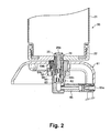
- the fluid reservoir 20 includes bottle 21, cap 22 threaded onto and covering the opening of the bottle 21, and connection part 23 projecting from the cap 22.
- the dental apparatus body 50 has fluid reservoir receptor section 61, which has reception part 62 in a concave shape for receiving the connection part 23 of the reservoir 20.
- connection part 23 of the fluid reservoir 20 is discussed in detail.
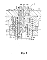
- connection part 23 of the fluid reservoir 20 mainly includes cylindrical member 24, shaft member 25, coil spring 26, nut 27, and stop pin 28. On the outer surface of the cylindrical member 24, O-rings 29 and stop ring 30 are fit.
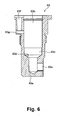
- the cylindrical member 24 has a through hole 24a extending centrally and axially through the cylindrical member 24 and having step 24b in the middle to form an enlarged hole portion.
- vertical hole 24c is provided in the upper part of the cylindrical member 24, which hole 24c is bent radially outwardly and ends in opening 24c' .
- a transverse hole 24d is provided through the outer surface of the cylindrical member 24, in communication with the through hole 24a.
- step 24b of the through hole 24a is formed so that the upper end of the coil spring 26 abuts the step 24b, and the lower enlarged hole portion of the through hole 24a below the step 24b accommodates the nut 27.
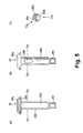
- the shaft member 25 has shank 25b extending axially, and flange 25a integrally formed on the top of the shank 25b.
- the flange 25a has groove 25c in its lower surface to fit O-ring 31 therein.
- the shank 25b has axial channel 25d formed in its outer surface over almost its entire length, and a short slot 25e, which is shorter than the axial channel 25d, and provided also in the outer surface of the shank 25b in a different circumferential position from the channel 25d.
- the shank 25b has lower part 25f having threads on its surface, onto which the nut 27 is screwed.
- connection part 23 is assembled by fitting the O-ring 31 in the groove 25c on the flange 25a of the shaft member 25, inserting the shank 25b of the shaft member 25 into the through hole 24a of the cylindrical member 24, placing the coil spring 26 around the lower portion of the shank 25b, and threading the nut 27 onto the lower part 25f so that the coil spring 26 is compressed and confined between the nut 27 and the step 24b.
- the stop pin 28 is inserted into the transverse hole 24d of the cylindrical member 24 and into the short slot 25e of the shaft member 25 to prevent the shaft member 25 from rotating around its axis with respect to the cylindrical member 24.
- connection part 23 is then connected to the cap 22 of the fluid reservoir 20 by threading the upper part 24e of the cylindrical member 24 into the cap 22. Further, the O-rings 29 are fit in the annular grooves 24g and 24h and the stop ring 30 in the groove 24f on the outer surface of the cylindrical member 24.
- the space defined between the axial channel 25d of the shaft member 25 and the inner surface of the through hole 24a of the cylindrical member 24 functions as a passage for the fluid in the fluid reservoir 20.
- the vertical hole 24c of the cylindrical member 24 functions as a passage for taking external air into the fluid reservoir 20.
- the fluid reservoir 20 is attached to the reception part 62, so that the shaft member 25 is shown slightly pressed up.
- the shaft member 25 is thrusted downwards by means of the coil spring 26, which brings the O-ring 31 on the flange 25a into tight contact with the upper end surface of the cylindrical member 24, so that the openings of the fluid passage and the passage for the external air are closed.
- the reception part 62 mainly includes casing 63, valve 64a, and releaser member 69.
- the casing 63 has an axial hole 63b provided in the casing 63 leaving the bottom 63a.
- the diameter of the hole 63b is slightly reduced from that of the upper portion of the hole 63b to form reduced diameter section 63c with a step between the upper section of the axial hole 63b and the reduced diameter section 63c.
- tapered section 63d is provided below which a further reduced diameter section is formed.
- a transverse hole 63e extends through the outer surface of the casing 63 in its lower end part to communicate with the axial hole 63b in the further reduced diameter section.
- valve seat 63f in the form of an axial hole is provided, and transverse hole 63g extends through the outer surface of the casing 63 across the bottom of the valve seat 63f into the axial hole 63b.
- valve 64a is fit and fixed with valve fixing means 64b.
- the casing 63 is fit in the fluid reservoir receptor section 61 with packing 66 (Fig. 3) being fit in the transverse hole 63g, and fixed to the receptor section 61 with first and second fixing means 67 and 68.
- Connector tube 65 is connected at one end to the transverse hole 63e, and opening 65a of the connector tube 65 at the other end is connected to a tube pump (not shown).
- the releaser member 69 has base 69a having three cut-outs 69c having arc sections, and shank 69b extending axially upwardly from the base 69a.
- This releaser member 69 is placed in the casing 63, with the base 69a being fit in the reduced diameter section 63c.
- the space defined by each cut-out 69c and the inner surface of the reduced diameter section 63c functions as a fluid passage.
- the fluid in the fluid reservoir 20 is allowed to flow, as shown by chain double-dashed arrow W in Fig. 3, through an opening between the flange 25a and the opening of the cylindrical member 24 downwardly into the passage defined by the axial channel 25d of the shaft member 25 and the inner surface of the through hole 24a of the cylindrical member 24, further through the passages defined by the cut-outs 69c of the releaser member 69 and the inner surface of the reduced diameter section 63c of the casing 63, and then through the connector tube 65 and its opening 65a into the tube pump.
- the dental apparatus body 50 mainly includes control substrate 51, power and pump substrate 52, oscillation substrate 53, pump motor 54, and water supply line 55.
- the control substrate 51 is provided with operation circuits for transmitting signals from operation buttons to microcomputer circuits, microcomputer circuits for ON/OFF control of other circuits in response to signal F received through terminal 58 from a foot switch as well as signals from the operation circuits, and display circuits for displaying the operation status of the microcomputer circuits by means of LEDs.
- the power and pump substrate 52 is provided with pump control circuits for controlling the pump motor 54 in response to signals from motor speed adjusting device 59 and the microcomputer circuits, electromagnetic valve control circuits for opening and closing electromagnetic valve 55b in response to signals from the microcomputer circuits, and main power supply circuits for supplying power to each circuit.
- Electric pathway 57 to the main power supply circuits transmits electricity through AC inlet 57a, open/close switch 57b, and power transformer 57c into the main power supply circuits.
- the open/close switch 57b is switched ON/OFF by means of power switch 57d, and the power input is stepped down to a predetermined voltage by means of the power transformer 57c.
- the oscillation substrate 53 is provided with light power supply circuits for switching ON/OFF a light built in the dental handpiece 40, and ultrasonic transmitter circuits for performing sweep oscillation to search for the resonance point of an electrostriction transducer built in the dental handpiece 40 and tip 41, and locking at the resonance point once it is found in the second cycle. Signals from the light power supply circuits and the ultrasonic transmitter circuits are output via output terminal 56.
- the water supply line 55 supplies water, such as tap water, to the dental handpiece 40, and includes terminal 55a for taking water into the line, electromagnetic valve 55b, water control valve 55c, and output terminal 56, in series.
- the electromagnetic valve control circuits of the power and pump substrate 52 are activated to open/close the electromagnetic valve 55b in response to ON/OFF of the foot switch.
- the amount of water is adjusted with the water control valve 55c, and a suitable amount of water is introduced into the dental handpiece 40 through the output terminal 56 and junction connector 45, and injected through the injection nozzle located at the tip of the handpiece 40.
- the pump control circuits of the power and pump substrate 52 are activated to start/stop the rotation of the pump motor 54 in response to ON/OFF of the foot switch.
- the pump motor 54 presses the tube pump to inject the liquid due to the pressure change therein.
- the amount of the liquid is adjusted by increasing/decreasing the rotation speed of the pump motor 54 with the pump control circuits, which is operated by the motor speed adjusting device 59.
- the liquid discharged from the tube pump is lead to the junction connector 45 and supplied to the dental handpiece 40.
- a check valve is provided both on the input side of the liquid from the fluid reservoir 20 and on the input side of water, such as tap water, to prevent backflow of the liquid and water.
Landscapes
- Health & Medical Sciences (AREA)
- Dentistry (AREA)
- Epidemiology (AREA)
- Life Sciences & Earth Sciences (AREA)
- Animal Behavior & Ethology (AREA)
- General Health & Medical Sciences (AREA)
- Public Health (AREA)
- Veterinary Medicine (AREA)
- Engineering & Computer Science (AREA)
- Water Supply & Treatment (AREA)
- Oral & Maxillofacial Surgery (AREA)
- Dental Tools And Instruments Or Auxiliary Dental Instruments (AREA)
Applications Claiming Priority (2)
| Application Number | Priority Date | Filing Date | Title |
|---|---|---|---|
| JP2003378427A JP3585484B1 (ja) | 2003-11-07 | 2003-11-07 | 歯科用機器及びこれに用いる液体槽 |
| JP2003378427 | 2003-11-07 |
Publications (2)
| Publication Number | Publication Date |
|---|---|
| EP1529496A2 true EP1529496A2 (de) | 2005-05-11 |
| EP1529496A3 EP1529496A3 (de) | 2006-01-04 |
Family
ID=33475606
Family Applications (1)
| Application Number | Title | Priority Date | Filing Date |
|---|---|---|---|
| EP04026387A Withdrawn EP1529496A3 (de) | 2003-11-07 | 2004-11-05 | Dentalvorrichtung und Flüssigkeitsbehälter dafür |
Country Status (3)
| Country | Link |
|---|---|
| US (1) | US7131838B2 (de) |
| EP (1) | EP1529496A3 (de) |
| JP (1) | JP3585484B1 (de) |
Cited By (2)
| Publication number | Priority date | Publication date | Assignee | Title |
|---|---|---|---|---|
| EP1709927A1 (de) * | 2005-04-04 | 2006-10-11 | Sirona Dental Systems GmbH | Einrichtung zum Anschließen eines Fluidbehälters an ein Dentalgerät, Dentalgerät mit einer solchen Einrichtung und Fluidbehälter zur Verwendung mit einer solchen Einrichtung |
| EP2529689A1 (de) * | 2011-06-02 | 2012-12-05 | Nakanishi Inc. | Flüssigkeitsbehälter und Zahnvorrichtung |
Families Citing this family (62)
| Publication number | Priority date | Publication date | Assignee | Title |
|---|---|---|---|---|
| US7147468B2 (en) | 2002-12-31 | 2006-12-12 | Water Pik, Inc. | Hand held oral irrigator |
| USD802120S1 (en) | 2007-02-27 | 2017-11-07 | Water Pik, Inc. | Tip for oral irrigator |
| EP2103272B1 (de) | 2008-03-05 | 2017-06-14 | W & H Dentalwerk Bürmoos GmbH | Medizinische, insbesondere dentalmedizinische, Behandlungseinrichtung mit einem Flüssigkeitsbehälter |
| US10258442B2 (en) | 2009-03-20 | 2019-04-16 | Water Pik, Inc. | Oral irrigator appliance with radiant energy delivery for bactericidal effect |
| US20100251867A1 (en) * | 2009-04-01 | 2010-10-07 | Ping Shao | Saw having a coolant supply |
| US8296898B1 (en) | 2010-02-10 | 2012-10-30 | Sprint Communications Company L.P. | Cleaning electrical connections |
| US10105201B2 (en) | 2012-10-11 | 2018-10-23 | Water Pik, Inc. | Interdental cleaner using water supply |
| KR101431802B1 (ko) * | 2013-02-15 | 2014-08-19 | (주)인일정공 | 치과용 시린지의 제어밸브 |
| AU2014244217B2 (en) * | 2013-03-14 | 2016-11-24 | Water Pik, Inc. | Oral irrigator with massage mode |
| USD714929S1 (en) | 2013-03-14 | 2014-10-07 | Water Pik, Inc. | Base for water flosser |
| US9642677B2 (en) | 2013-03-14 | 2017-05-09 | Water Pik, Inc. | Oral irrigator with massage mode |
| KR102521242B1 (ko) | 2013-03-15 | 2023-04-17 | 워터 피크 인코포레이티드 | 기계 구동식 음파 칫솔 및 워터 플로서 |
| US9980793B2 (en) | 2013-11-27 | 2018-05-29 | Water Pik, Inc. | Oral hygiene system |
| CA2932074C (en) | 2013-11-27 | 2018-04-17 | Water Pik, Inc. | Oral irrigator with slide pause switch |
| CN203693808U (zh) | 2013-12-12 | 2014-07-09 | 洁碧有限公司 | 牙科用喷水器 |
| USD772396S1 (en) | 2014-12-01 | 2016-11-22 | Water Pik, Inc. | Handheld oral irrigator |
| CN205586102U (zh) | 2014-12-01 | 2016-09-21 | 洁碧有限公司 | 防水无线口腔冲洗器 |
| USD780908S1 (en) | 2015-11-03 | 2017-03-07 | Water Pik, Inc. | Handheld oral irrigator |
| USD822196S1 (en) | 2016-01-14 | 2018-07-03 | Water Pik, Inc. | Oral irrigator |
| USD802747S1 (en) | 2016-07-19 | 2017-11-14 | Water Pik, Inc. | Reservoir for oral irrigator |
| USD796028S1 (en) | 2016-07-19 | 2017-08-29 | Water Pik, Inc. | Oral irrigator |
| US10835356B2 (en) | 2016-01-25 | 2020-11-17 | Water Pik, Inc. | Swivel assembly for oral irrigator handle |
| CN114748199B (zh) | 2016-01-25 | 2025-04-22 | 洁碧有限公司 | 减小形状因子的口腔冲洗器 |
| USD782656S1 (en) | 2016-01-25 | 2017-03-28 | Water Pik, Inc. | Oral irrigator |
| USD783809S1 (en) | 2016-01-25 | 2017-04-11 | Water Pik, Inc. | Oral irrigator handle |
| USD804018S1 (en) | 2016-07-19 | 2017-11-28 | Water Pik, Inc. | Base for an oral irrigator |
| USD819956S1 (en) | 2016-01-25 | 2018-06-12 | Water Pik, Inc. | Kit bag |
| USD786422S1 (en) | 2016-01-25 | 2017-05-09 | Water Pik, Inc. | Oral irrigator |
| USD794773S1 (en) | 2016-07-19 | 2017-08-15 | Water Pik, Inc. | Oral irrigator |
| USD804016S1 (en) | 2016-02-05 | 2017-11-28 | Water Pik, Inc. | Handheld oral irrigator |
| USD783810S1 (en) | 2016-02-22 | 2017-04-11 | Water Pik, Inc. | Handle for an oral irrigator |
| USD809650S1 (en) | 2016-02-22 | 2018-02-06 | Water Pik, Inc. | Oral irrigator |
| USD782657S1 (en) | 2016-03-02 | 2017-03-28 | Water Pik, Inc. | Oral irrigator handle |
| USD802119S1 (en) | 2016-03-02 | 2017-11-07 | Water Pik, Inc. | Oral irrigator |
| US10993867B2 (en) | 2016-03-02 | 2021-05-04 | Water Pik, Inc. | Actuation assembly for an oral irrigator |
| USD807822S1 (en) | 2016-07-19 | 2018-01-16 | Water Pik, Inc. | Power supply cartridge |
| USD809651S1 (en) | 2016-07-19 | 2018-02-06 | Water Pik, Inc. | Combination base and reservoir for an oral irrigator |
| USD840023S1 (en) | 2016-12-15 | 2019-02-05 | Water Pik, Inc. | Oral irrigator reservoir |
| USD867579S1 (en) | 2016-12-15 | 2019-11-19 | Water Pik, Inc. | Oral irrigator unit |
| CN110312491B (zh) | 2016-12-15 | 2022-10-28 | 洁碧有限公司 | 带有磁性附连的口腔冲洗器 |
| USD840022S1 (en) | 2016-12-15 | 2019-02-05 | Water Pik, Inc. | Oral irrigator handle |
| USD833000S1 (en) | 2016-12-15 | 2018-11-06 | Water Pik, Inc. | Oral irrigator unit |
| USD822825S1 (en) | 2016-12-15 | 2018-07-10 | Water Pik, Inc. | Oral irrigator unit |
| USD829886S1 (en) | 2016-12-15 | 2018-10-02 | Water Pik, Inc. | Oral irrigator base |
| WO2018112416A1 (en) | 2016-12-15 | 2018-06-21 | Water Pik, Inc. | Pause valve and swivel assemblies for oral irrigator handle |
| USD822826S1 (en) | 2016-12-15 | 2018-07-10 | Water Pik, Inc. | Oral irrigator base |
| USD832420S1 (en) | 2016-12-15 | 2018-10-30 | Water Pik, Inc. | Oral irrigator base |
| USD825741S1 (en) | 2016-12-15 | 2018-08-14 | Water Pik, Inc. | Oral irrigator handle |
| USD839409S1 (en) | 2016-12-15 | 2019-01-29 | Water Pik, Inc. | Oral irrigator unit |
| USD833600S1 (en) | 2016-12-15 | 2018-11-13 | Water Pik, Inc. | Oral irrigator reservoir |
| USD832418S1 (en) | 2016-12-15 | 2018-10-30 | Water Pik, Inc. | Oral irrigator base |
| USD834180S1 (en) | 2016-12-15 | 2018-11-20 | Water Pik, Inc. | Oral irrigator base |
| USD832419S1 (en) | 2016-12-15 | 2018-10-30 | Water Pik, Inc. | Oral irrigator unit |
| USD833602S1 (en) | 2017-02-06 | 2018-11-13 | Water Pik, Inc. | Oral irrigator base |
| USD829887S1 (en) | 2017-02-06 | 2018-10-02 | Water Pik, Inc. | Oral irrigator reservoir |
| USD833601S1 (en) | 2017-02-06 | 2018-11-13 | Water Pik, Inc. | Oral irrigator |
| USD868243S1 (en) | 2018-03-16 | 2019-11-26 | Water Pik, Inc. | Oral irrigator tip |
| USD877324S1 (en) | 2018-05-17 | 2020-03-03 | Water Pik, Inc. | Oral irrigator handle |
| USD888936S1 (en) | 2019-02-22 | 2020-06-30 | Water Pik, Inc. | Cordless water flosser |
| USD889636S1 (en) | 2019-02-22 | 2020-07-07 | Water Pik, Inc. | Water flosser |
| USD966498S1 (en) | 2020-09-15 | 2022-10-11 | Water Pik, Inc. | Oral irrigator |
| USD1016274S1 (en) | 2021-02-16 | 2024-02-27 | Water Pik, Inc. | Oral irrigator |
Citations (1)
| Publication number | Priority date | Publication date | Assignee | Title |
|---|---|---|---|---|
| JP2002320628A (ja) | 2001-03-23 | 2002-11-05 | Ferton Holding Sa | 液体槽付歯科用機器 |
Family Cites Families (6)
| Publication number | Priority date | Publication date | Assignee | Title |
|---|---|---|---|---|
| DE3312705A1 (de) | 1983-04-08 | 1984-10-11 | Kaltenbach & Voigt Gmbh & Co, 7950 Biberach | Kupplung fuer aerztliche, insbesondere zahnaerztliche handstueckteile |
| DE3937876A1 (de) * | 1989-11-14 | 1991-05-16 | Braun Ag | Mundpflegegeraet |
| JPH03264013A (ja) | 1990-03-14 | 1991-11-25 | Matsushita Electric Ind Co Ltd | 着脱式液体タンクのシール装置 |
| DE4138672C2 (de) * | 1991-11-25 | 1995-01-05 | Kaltenbach & Voigt | Verfahren und Vorrichtung zum Reinigen einer Leitung zum Zuführen von Beandlungsflüssigkeit, insbesondere Kühlflüssigkeit, einer ärztlichen Behandlungseinrichtung sowie ärztliche Behandlungseinrichtung |
| US6206058B1 (en) | 1998-11-09 | 2001-03-27 | The Procter & Gamble Company | Integrated vent and fluid transfer fitment |
| JP4061776B2 (ja) | 1999-05-24 | 2008-03-19 | 松下電器産業株式会社 | カートリッジタンク |
-
2003
- 2003-11-07 JP JP2003378427A patent/JP3585484B1/ja not_active Expired - Fee Related
-
2004
- 2004-11-05 EP EP04026387A patent/EP1529496A3/de not_active Withdrawn
- 2004-11-08 US US10/982,825 patent/US7131838B2/en not_active Expired - Lifetime
Patent Citations (1)
| Publication number | Priority date | Publication date | Assignee | Title |
|---|---|---|---|---|
| JP2002320628A (ja) | 2001-03-23 | 2002-11-05 | Ferton Holding Sa | 液体槽付歯科用機器 |
Cited By (6)
| Publication number | Priority date | Publication date | Assignee | Title |
|---|---|---|---|---|
| EP1709927A1 (de) * | 2005-04-04 | 2006-10-11 | Sirona Dental Systems GmbH | Einrichtung zum Anschließen eines Fluidbehälters an ein Dentalgerät, Dentalgerät mit einer solchen Einrichtung und Fluidbehälter zur Verwendung mit einer solchen Einrichtung |
| EP2529689A1 (de) * | 2011-06-02 | 2012-12-05 | Nakanishi Inc. | Flüssigkeitsbehälter und Zahnvorrichtung |
| CN102805671A (zh) * | 2011-06-02 | 2012-12-05 | 株式会社中西 | 液体箱和牙科用设备 |
| CN102805671B (zh) * | 2011-06-02 | 2015-01-21 | 株式会社中西 | 液体箱和牙科用设备 |
| TWI489976B (zh) * | 2011-06-02 | 2015-07-01 | Nakanishi Inc | Liquid tank and dental machine |
| US9320574B2 (en) | 2011-06-02 | 2016-04-26 | Nakanishi Inc. | Liquid tank and dental device |
Also Published As
| Publication number | Publication date |
|---|---|
| JP3585484B1 (ja) | 2004-11-04 |
| US20050100858A1 (en) | 2005-05-12 |
| US7131838B2 (en) | 2006-11-07 |
| EP1529496A3 (de) | 2006-01-04 |
| JP2005137660A (ja) | 2005-06-02 |
Similar Documents
| Publication | Publication Date | Title |
|---|---|---|
| US7131838B2 (en) | Dental apparatus and fluid reservoir for the same | |
| US11730577B2 (en) | Oral cavity washing device | |
| US10016254B2 (en) | Dental water jet | |
| ES2718685T3 (es) | Irrigador bucal con interruptor de pausa deslizante | |
| US5171146A (en) | Syringe for washing teeth root canals | |
| EP1705297B1 (de) | Sanitärarmatur mit einem lichtleitenden Ausflussrohr | |
| US6564968B1 (en) | Automated fluid dispenser | |
| WO2017018143A1 (ja) | 液体用電磁弁、液体用電磁弁の製造方法、及び洗濯機 | |
| US4361138A (en) | Ventilation/feedwater switching apparatus for endoscope | |
| JP5450513B2 (ja) | 液体槽及び歯科用機器 | |
| ATE547750T1 (de) | Durchflussmengenregler | |
| KR100530848B1 (ko) | 약액 공급량 조절기 | |
| US20040261173A1 (en) | Foot massaging tub having an operation control device | |
| CN112919699B (zh) | 水处理系统 | |
| EP1060800A2 (de) | Steuereinrichtung für Hochdruckreinigungsgeräte und dergleichen | |
| US20100227293A1 (en) | Dental handpiece of center-injection type | |
| US20030183595A1 (en) | Air inlet sleeve of baby's bottle | |
| JP4554808B2 (ja) | 内視鏡用給水装置 | |
| NO20031311L (no) | Vannkran | |
| KR200196228Y1 (ko) | 역투입방지용 병뚜껑 | |
| EP0453493A1 (de) | Spritze zum waschen von zahnwurzelkanälen. | |
| JP3938659B2 (ja) | 出湯装置 | |
| JP3911169B2 (ja) | 内視鏡 | |
| KR200408182Y1 (ko) | 생활용수 급수시스템의 감지장치 | |
| JP2004124578A (ja) | 遠隔操作式排水栓装置とそれに用いられる引き上げ用治具 |
Legal Events
| Date | Code | Title | Description |
|---|---|---|---|
| PUAI | Public reference made under article 153(3) epc to a published international application that has entered the european phase |
Free format text: ORIGINAL CODE: 0009012 |
|
| AK | Designated contracting states |
Kind code of ref document: A2 Designated state(s): AT BE BG CH CY CZ DE DK EE ES FI FR GB GR HU IE IS IT LI LU MC NL PL PT RO SE SI SK TR |
|
| AX | Request for extension of the european patent |
Extension state: AL HR LT LV MK YU |
|
| PUAL | Search report despatched |
Free format text: ORIGINAL CODE: 0009013 |
|
| AK | Designated contracting states |
Kind code of ref document: A3 Designated state(s): AT BE BG CH CY CZ DE DK EE ES FI FR GB GR HU IE IS IT LI LU MC NL PL PT RO SE SI SK TR |
|
| AX | Request for extension of the european patent |
Extension state: AL HR LT LV MK YU |
|
| RIC1 | Information provided on ipc code assigned before grant |
Ipc: A61C 17/02 20060101ALI20051115BHEP Ipc: A61C 1/00 20060101AFI20050223BHEP |
|
| 17P | Request for examination filed |
Effective date: 20060523 |
|
| AKX | Designation fees paid |
Designated state(s): AT CH DE FR GB IT LI |
|
| STAA | Information on the status of an ep patent application or granted ep patent |
Free format text: STATUS: THE APPLICATION HAS BEEN WITHDRAWN |
|
| 18W | Application withdrawn |
Effective date: 20110413 |