EP1529490A1 - X-ray ct imaging method and x-ray ct apparatus - Google Patents
X-ray ct imaging method and x-ray ct apparatus Download PDFInfo
- Publication number
- EP1529490A1 EP1529490A1 EP04256824A EP04256824A EP1529490A1 EP 1529490 A1 EP1529490 A1 EP 1529490A1 EP 04256824 A EP04256824 A EP 04256824A EP 04256824 A EP04256824 A EP 04256824A EP 1529490 A1 EP1529490 A1 EP 1529490A1
- Authority
- EP
- European Patent Office
- Prior art keywords
- rectilinear motion
- ray
- roi
- image
- projection data
- Prior art date
- Legal status (The legal status is an assumption and is not a legal conclusion. Google has not performed a legal analysis and makes no representation as to the accuracy of the status listed.)
- Withdrawn
Links
- 238000003384 imaging method Methods 0.000 title description 6
- 230000033001 locomotion Effects 0.000 claims abstract description 213
- 238000000034 method Methods 0.000 claims description 67
- 238000013170 computed tomography imaging Methods 0.000 claims description 38
- 238000002591 computed tomography Methods 0.000 description 79
- 238000010586 diagram Methods 0.000 description 30
- 238000012545 processing Methods 0.000 description 9
- 238000013480 data collection Methods 0.000 description 7
- 230000001133 acceleration Effects 0.000 description 6
- 230000005540 biological transmission Effects 0.000 description 5
- 238000012937 correction Methods 0.000 description 4
- 238000001914 filtration Methods 0.000 description 4
- 230000003247 decreasing effect Effects 0.000 description 3
- 230000010412 perfusion Effects 0.000 description 3
- 239000002872 contrast media Substances 0.000 description 2
- 230000002123 temporal effect Effects 0.000 description 2
- 230000009466 transformation Effects 0.000 description 2
- 238000004364 calculation method Methods 0.000 description 1
- 238000007796 conventional method Methods 0.000 description 1
- 238000013213 extrapolation Methods 0.000 description 1
- 238000012805 post-processing Methods 0.000 description 1
- 238000007781 pre-processing Methods 0.000 description 1
- 230000035945 sensitivity Effects 0.000 description 1
Images








Classifications
-
- A—HUMAN NECESSITIES
- A61—MEDICAL OR VETERINARY SCIENCE; HYGIENE
- A61B—DIAGNOSIS; SURGERY; IDENTIFICATION
- A61B6/00—Apparatus or devices for radiation diagnosis; Apparatus or devices for radiation diagnosis combined with radiation therapy equipment
- A61B6/02—Arrangements for diagnosis sequentially in different planes; Stereoscopic radiation diagnosis
- A61B6/03—Computed tomography [CT]
-
- A—HUMAN NECESSITIES
- A61—MEDICAL OR VETERINARY SCIENCE; HYGIENE
- A61B—DIAGNOSIS; SURGERY; IDENTIFICATION
- A61B6/00—Apparatus or devices for radiation diagnosis; Apparatus or devices for radiation diagnosis combined with radiation therapy equipment
- A61B6/02—Arrangements for diagnosis sequentially in different planes; Stereoscopic radiation diagnosis
- A61B6/03—Computed tomography [CT]
- A61B6/032—Transmission computed tomography [CT]
-
- A—HUMAN NECESSITIES
- A61—MEDICAL OR VETERINARY SCIENCE; HYGIENE
- A61B—DIAGNOSIS; SURGERY; IDENTIFICATION
- A61B6/00—Apparatus or devices for radiation diagnosis; Apparatus or devices for radiation diagnosis combined with radiation therapy equipment
- A61B6/02—Arrangements for diagnosis sequentially in different planes; Stereoscopic radiation diagnosis
- A61B6/027—Arrangements for diagnosis sequentially in different planes; Stereoscopic radiation diagnosis characterised by the use of a particular data acquisition trajectory, e.g. helical or spiral
-
- A—HUMAN NECESSITIES
- A61—MEDICAL OR VETERINARY SCIENCE; HYGIENE
- A61B—DIAGNOSIS; SURGERY; IDENTIFICATION
- A61B6/00—Apparatus or devices for radiation diagnosis; Apparatus or devices for radiation diagnosis combined with radiation therapy equipment
- A61B6/46—Arrangements for interfacing with the operator or the patient
- A61B6/467—Arrangements for interfacing with the operator or the patient characterised by special input means
- A61B6/469—Arrangements for interfacing with the operator or the patient characterised by special input means for selecting a region of interest [ROI]
-
- A—HUMAN NECESSITIES
- A61—MEDICAL OR VETERINARY SCIENCE; HYGIENE
- A61B—DIAGNOSIS; SURGERY; IDENTIFICATION
- A61B6/00—Apparatus or devices for radiation diagnosis; Apparatus or devices for radiation diagnosis combined with radiation therapy equipment
- A61B6/54—Control of apparatus or devices for radiation diagnosis
- A61B6/542—Control of apparatus or devices for radiation diagnosis involving control of exposure
-
- A—HUMAN NECESSITIES
- A61—MEDICAL OR VETERINARY SCIENCE; HYGIENE
- A61B—DIAGNOSIS; SURGERY; IDENTIFICATION
- A61B6/00—Apparatus or devices for radiation diagnosis; Apparatus or devices for radiation diagnosis combined with radiation therapy equipment
- A61B6/40—Arrangements for generating radiation specially adapted for radiation diagnosis
- A61B6/4064—Arrangements for generating radiation specially adapted for radiation diagnosis specially adapted for producing a particular type of beam
- A61B6/4085—Cone-beams
-
- Y—GENERAL TAGGING OF NEW TECHNOLOGICAL DEVELOPMENTS; GENERAL TAGGING OF CROSS-SECTIONAL TECHNOLOGIES SPANNING OVER SEVERAL SECTIONS OF THE IPC; TECHNICAL SUBJECTS COVERED BY FORMER USPC CROSS-REFERENCE ART COLLECTIONS [XRACs] AND DIGESTS
- Y10—TECHNICAL SUBJECTS COVERED BY FORMER USPC
- Y10S—TECHNICAL SUBJECTS COVERED BY FORMER USPC CROSS-REFERENCE ART COLLECTIONS [XRACs] AND DIGESTS
- Y10S378/00—X-ray or gamma ray systems or devices
- Y10S378/901—Computer tomography program or processor
Definitions
- the present invention relates to an X-ray CT (computed tomography) imaging method and an X-ray CT apparatus, and more particularly to an X-ray CT imaging method and an X-ray CT apparatus by which the distance of rectilinear motion in a helical scan can be reduced.
- X-ray CT computed tomography
- an X-ray CT apparatus that ensures a constant speed of rectilinear motion in a region of interest ROI by controlling rectilinear motion of a table, the control comprising: appending an acceleration section A before a front end position Ra of the region of interest ROI for which an CT image is to be created to define a rectilinear motion start point La; appending a deceleration section B after a back end position Rb of the region of interest ROI to define a rectilinear motion end point Lb; starting rectilinear motion of the table at a table position at which an X-ray tube 21 looks straight down on the rectilinear motion start point La; increasing the speed of rectilinear motion in the acceleration section A, driving rectilinear motion at a constant speed in the region of interest ROI and decreasing the speed of rectilinear motion in the deceleration section B; and stopping rectilinear motion at a table position at which the X-ray tube 21 looks straight down on the
- the table is rectilinearly moved while rotating the X-ray tube 21 and multi-row detector 24 around a subject to be imaged in a helical scan, although for convenience of illustration Figure 29 represents the rectilinear motion as if it occurred without rotating the X-ray tube 21 and multi-row detector 24.
- the conventional technique appends the acceleration section A before the region of interest ROI and the deceleration section B after the region of interest ROI.
- the present invention provides an X-ray CT imaging method for conducting a helical scan for collecting projection data while making relative rotation of at least one of an X-ray tube and a multi-row detector around a subject to be imaged and making relative rectilinear motion of them with respect to the subject to be imaged, said method characterized in comprising: defining a rectilinear motion start point and a rectilinear motion end point within a region of interest (ROI) for which a CT image is to be created; collecting projection data from said rectilinear motion start point to said rectilinear motion end point; and producing a CT image at a desired image position in said region of interest using the collected projection data.
- ROI region of interest
- relative rotation includes: for a subject to be imaged placed in between the X-ray tube and multi-row detector, rotating at least one of the X-ray tube and multi-row detector around the subject to be imaged without rotating the subject to be imaged; rotating the subject to be imaged around its axis without rotating the X-ray tube and multi-row detector; and rotating the subject to be imaged around its axis and counter-rotating at least one of the X-ray tube and multi-row detector around the subject to be imaged.
- the term "relative rectilinear motion” includes: for a subject to be imaged placed in between the X-ray tube and multi-row detector, rectilinearly moving the subject to be imaged (or the table on which the subject to be imaged is laid) without rectilinearly moving the X-ray tube and multi-row detector; rectilinearly moving the X-ray tube and multi-row detector without rectilinearly moving the subject to be imaged (or the table on which the subject to be imaged is laid); and rectilinearly moving the subject to be imaged (or the table on which the subject to be imaged is laid) and rectilinearly moving the X-ray tube and multi-row detector in the opposite direction.
- a rectilinear motion start point and a rectilinear motion end point are defined within a region of interest, and projection data are collected from the rectilinear motion start point to the rectilinear motion end point.
- the X-ray beam covers the ROI front end even if the rectilinear motion start point is defined within the region of interest because the X-ray beam thickness in the direction of rectilinear motion is large.
- the X-ray beam covers the ROI back end even if the rectilinear motion end point is defined within the region of interest.
- a CT image can be created at a desired image position from the front end to the back end of the region of interest using the collected projection data.
- the distance of rectilinear motion can be made shorter than the region of interest. Accordingly, the imaging time can be reduced. Moreover, the cycle time for reciprocal rectilinear motion can be reduced. Furthermore, the X-ray exposure dose can be reduced.
- the CT image may be created by a two-dimensional or three-dimensional image reconstruction technique.
- the present invention provides the X-ray CT imaging method having the aforementioned configuration, characterized in that: said rectilinear motion start point lies inward from the ROI front end position by half or approximately half of the X-ray beam thickness in the direction of rectilinear motion.
- the X-ray beam thickness in the direction of rectilinear motion refers to the X-ray beam thickness in the direction of rectilinear motion at the position of the subject to be imaged placed in between the X-ray tube and multi-row detector.
- the X-ray beam covers the subject to be imaged anterior to the start point by half or approximately half of the X-ray beam thickness in the direction of rectilinear motion.
- the rectilinear motion start point is therefore defined inward from the ROI front end position by half or approximately half of the X-ray beam thickness in the direction of rectilinear motion.
- the present invention provides the X-ray CT imaging method having the aforementioned configuration, characterized in that: said rectilinear motion end point lies inward from the ROI back end position by half or about half of the X-ray beam thickness in the direction of rectilinear motion.
- the X-ray beam thickness in the direction of rectilinear motion refers to the X-ray beam thickness in the direction of rectilinear motion at the position of the subject to be imaged placed in between the X-ray tube and multi-row detector.
- the X-ray beam covers the subject to be imaged posterior to the end point by half or approximately half of the X-ray beam thickness in the direction of rectilinear motion.
- the rectilinear motion end point is therefore defined inward from the ROI front end position by half or approximately half of the X-ray beam thickness in the direction of rectilinear motion.
- the present invention provides an X-ray CT imaging method for conducting a helical scan for collecting projection data while making relative rotation of at least one of an X-ray tube and a multi-row detector around a subject to be imaged and making relative rectilinear motion of them with respect to the subject to be imaged, said method characterized in comprising: collecting projection data from a rectilinear motion start point to a rectilinear motion end point; and creating a CT image at a desired image position in a region of interest (ROI) from an ROI front end position anterior to said rectilinear motion start point to an ROI back end position posterior to said rectilinear motion end point using the collected projection data.
- ROI region of interest
- the phrase "relative rotation” includes: for a subject to be imaged placed in between the X-ray tube and multi-row detector, rotating at least one of the X-ray tube and multi-row detector around the subject to be imaged without rotating the subject to be imaged; rotating the subject to be imaged around its axis without rotating the X-ray tube and multi-row detector; and rotating the subject to be imaged around its axis and counter-rotating at least one of the X-ray tube and multi-row detector around the subject to be imaged.
- the phrase "relative rectilinear motion” includes: for a subject to be imaged placed in between the X-ray tube and multi-row detector, rectilinearly moving the subject to be imaged (or the table on which the subject to be imaged is laid) without rectilinearly moving the X-ray tube and multi-row detector; rectilinearly moving the X-ray tube and multi-row detector without rectilinearly moving the subject to be imaged (or the table on which the subject to be imaged is laid); and rectilinearly moving the subject to be imaged (or the table on which the subject to be imaged is laid) and rectilinearly moving the X-ray tube and multi-row detector in the opposite direction.
- the ROI front end is defined anterior to the rectilinear motion start point
- the ROI back end is defined posterior to the rectilinear motion end point
- projection data are collected from the rectilinear motion start point to the rectilinear motion end point.
- the X-ray beam covers the ROI front end even if the ROI front end is defined anterior to the rectilinear motion start point because the X-ray beam thickness in the direction of rectilinear motion is large.
- the X-ray beam covers the ROI back end even if the ROI back end is defined posterior to the rectilinear motion end point.
- a CT image can be created at a desired image position from the ROI front end to the ROI back end using the collected projection data.
- the distance of rectilinear motion can be made shorter than the region of interest. Accordingly, the imaging time can be reduced. Moreover, the cycle time for reciprocal rectilinear motion can be reduced. Furthermore, the X-ray exposure dose can be reduced.
- the present invention provides the X-ray CT imaging method having the aforementioned configuration, characterized in that: said ROI front end position lies anterior to said rectilinear motion start point by half or approximately half of the X-ray beam thickness in the direction of rectilinear motion.
- the X-ray beam thickness in the direction of rectilinear motion refers to the X-ray beam thickness in the direction of rectilinear motion at the position of the subject to be imaged placed in between the X-ray tube and multi-row detector.
- the X-ray beam covers the subject to be imaged anterior to the start point by half or approximately half of the X-ray beam thickness in the direction of rectilinear motion.
- the ROI front end position is therefore defined anterior to the rectilinear motion start point by half or approximately half of the X-ray beam thickness in the direction of rectilinear motion.
- the present invention provides the X-ray CT imaging method having the aforementioned configuration, characterized in that: said ROI back end position lies posterior to said rectilinear motion end point by half or approximately half of the X-ray beam thickness in the direction of rectilinear motion.
- the X-ray beam thickness in the direction of rectilinear motion refers to the X-ray beam thickness in the direction of rectilinear motion at the position of the subject to be imaged placed in between the X-ray tube and multi-row detector.
- the X-ray beam covers the subject to be imaged posterior to the end point by half or approximately half of the X-ray beam thickness in the direction of rectilinear motion.
- the ROI back end is therefore defined posterior to the rectilinear motion end point by half or approximately half of the X-ray beam thickness in the direction of rectilinear motion.
- the present invention provides the X-ray CT imaging method having the aforementioned configuration, characterized in comprising making reciprocal relative rectilinear motion by: making motion from said rectilinear motion start point to said rectilinear motion end point; then re-defining said rectilinear motion start point and said rectilinear motion end point as a new rectilinear motion end point and a new rectilinear motion start point, respectively; and making relative rectilinear motion in an opposite direction.
- the cycle time for reciprocal relative rectilinear motion can be reduced.
- temporal resolution at the same image position can be improved.
- the invention of this aspect is especially suitable for perfusion CT.
- the present invention provides the X-ray CT imaging method having the aforementioned configuration, characterized in comprising: collecting projection data while making said relative rotation at said rectilinear motion start point without making said relative rectilinear motion; reconstructing a CT image using the collected projection data; and starting said relative rectilinear motion based on a change in said CT image.
- the rectilinear motion start point is brought closer to the ROI center.
- the invention of this aspect is especially suitable for Smart Prep (GE) or Real Prep (Toshiba).
- the present invention provides the X-ray CT imaging method having the aforementioned configuration, characterized in comprising: creating a CT image by a three-dimensional image reconstruction technique.
- Known three-dimensional image reconstruction techniques include the Feldkamp method and the weighted Feldkamp method.
- the present invention provides the X-ray CT imaging method having the aforementioned configuration, characterized in that said three-dimensional image reconstruction technique is a three-dimensional backprojection method comprising: ordering the collected projection data based on the z-position of each view and extracting projection data corresponding to one line or a plurality of parallel lines at spacings of a plurality of pixels on an image reconstruction field; generating projection line data by multiplying said projection data by a cone beam reconstruction weight; generating image-positional line data by filtering said projection line data; determining backprojected pixel data of each pixel on the reconstruction field based on said image-positional line data; and determining backprojected data by adding the backprojected pixel data on a pixel-by-pixel basis for all views used in image reconstruction.
- said three-dimensional image reconstruction technique is a three-dimensional backprojection method comprising: ordering the collected projection data based on the z-position of each view and extracting projection data corresponding to one line or a plurality of parallel lines at spacings of a
- the volume of calculation can be significantly reduced.
- the present invention provides an X-ray CT apparatus characterized in comprising: an X-ray tube; a multi-row detector; helical scanning means for collecting projection data while making relative rotation of at least one of said X-ray tube and said multi-row detector around a subject to be imaged and making relative rectilinear motion of them with respect to the subject to be imaged, from a rectilinear motion start point to a rectilinear motion end point defined within a region of interest (ROI) for which a CT image is to be created; and image reconstructing means for producing a CT image at a desired image position in said region of interest using the collected projection data.
- ROI region of interest
- the X-ray CT imaging method in the first aspect is suitably implemented.
- the present invention provides the X-ray CT apparatus having the aforementioned configuration, characterized in that: said rectilinear motion start point lies inward from the ROI front end position by half or approximately half of the X-ray beam thickness in the direction of rectilinear motion.
- the X-ray CT imaging method in the second aspect is suitably implemented.
- the present invention provides the X-ray CT apparatus having the aforementioned configuration, characterized in that: said rectilinear motion end point lies inward from the ROI back end position by half or about half of the X-ray beam thickness in the direction of rectilinear motion.
- the X-ray CT imaging method in the third aspect is suitably implemented.
- the present invention provides an X-ray CT apparatus characterized in comprising: an X-ray tube; a multi-row detector; helical scanning means for collecting projection data from a rectilinear motion start point to a rectilinear motion end point while making relative rotation of at least one of said X-ray tube and said multi-row detector around a subject to be imaged and making relative rectilinear motion of them with respect to the subject to be imaged; and image reconstructing means for creating a CT image at a desired image position in a region of interest (ROI) from an ROI front end position anterior to said rectilinear motion start point to an ROI back end position posterior to said rectilinear motion end point using the collected projection data.
- ROI region of interest
- the X-ray CT imaging method in the fourth aspect is suitably implemented.
- the present invention provides the X-ray CT apparatus having the aforementioned configuration, characterized in that: said ROI front end position lies anterior to said rectilinear motion start point by half or approximately half of the X-ray beam thickness in the direction of rectilinear motion.
- the X-ray CT imaging method in the fifth aspect is suitably implemented.
- the present invention provides the X-ray CT apparatus having the aforementioned configuration, characterized in that: said ROI back end position lies posterior to said rectilinear motion end point by half or approximately half of the X-ray beam thickness in the direction of rectilinear motion.
- the X-ray CT imaging method in the sixth aspect is suitably implemented.
- the present invention provides the X-ray CT apparatus having the aforementioned configuration, characterized in that said helical scanning means collects the projection data while making reciprocal relative rectilinear motion by: making motion from said rectilinear motion start point to said rectilinear motion end point; then re-defining said rectilinear motion start point and said rectilinear motion end point as a new rectilinear motion end point and a new rectilinear motion start point, respectively; and making relative rectilinear motion in an opposite direction.
- the X-ray CT imaging method in the seventh aspect is suitably implemented.
- the present invention provides the X-ray CT apparatus having the aforementioned configuration, characterized in that: said helical scanning means collects projection data while making said relative rotation at said rectilinear motion start point without making said relative rectilinear motion; reconstructs a CT image using the collected projection data; and starts said relative rectilinear motion based on a change in said CT image.
- the X-ray CT imaging method in the eighth aspect is suitably implemented.
- the present invention provides the X-ray CT apparatus having the aforementioned configuration, characterized in that: said image reconstructing means creates a CT image by a three-dimensional image reconstruction technique.
- the X-ray CT imaging method in the ninth aspect is suitably implemented.
- the present invention provides the X-ray CT apparatus having the aforementioned configuration, characterized in that: said three-dimensional image reconstruction technique is a three-dimensional backprojection method comprising: ordering the collected projection data based on the z-position of each view and extracting projection data corresponding to one line or a plurality of parallel lines at spacings of a plurality of pixels on an image reconstruction field; generating projection line data by multiplying said projection data by a cone beam reconstruction weight; generating image-positional line data by filtering said projection line data; determining backprojected pixel data of each pixel on the reconstruction field based on said image-positional line data; and determining backprojected data by adding the backprojected pixel data on a pixel-by-pixel basis for all views used in image reconstruction.
- said three-dimensional image reconstruction technique is a three-dimensional backprojection method comprising: ordering the collected projection data based on the z-position of each view and extracting projection data corresponding to one line or a plurality of parallel lines at spacings of a
- the X-ray CT imaging method in the tenth aspect is suitably implemented.
- the distance of rectilinear motion in a helical scan can be reduced.
- the cycle time for reciprocal rectilinear motion can be reduced.
- the X-ray exposure dose can be reduced even if X-rays are constantly emitted during rectilinear motion.
- the X-ray CT imaging method and X-ray CT apparatus of the present invention can be employed in, for example, perfusion CT.
- Figure 1 is a block diagram showing the configuration of an X-ray CT apparatus 100 of Example 1.
- the X-ray CT apparatus 100 comprises an operation console 1, a table apparatus 10, and a scan gantry 20.
- the operation console 1 comprises an input device 2 for accepting inputs by a human operator, a central processing apparatus 3 for executing image reconstruction processing etc., a data collection buffer 5 for collecting projection data acquired at the scan gantry 20, a CRT 6 for displaying a CT image reconstructed from the projection data, and a storage device 7 for storing programs, data, and X-ray CT images.
- the table apparatus 10 comprises a table 12 for laying thereon a subject and transporting the subject into/out of a bore (cavity portion) of the scan gantry 20.
- the table 12 is vertically and horizontally/rectilinearly moved by a motor incorporated in the table apparatus 10.
- the scan gantry 20 comprises an X-ray tube 21, an X-ray controller 22, a collimator 23, a multi-row detector 24, a DAS (data acquisition system) 25, a rotator-side controller 26 for controlling the X-ray controller 22, collimator 23 and DAS 25, an overall controller 29 for communicating control signals etc. with the operation console 1 and imaging table 10, and a slip ring 30.
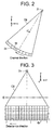
- Figures 2 and 3 are explanatory diagrams of the X-ray tube 21 and multi-row detector 24.
- the X-ray tube 21 and multi-row detector 24 rotate around an isocenter IC. Representing the direction of rectilinear motion of the table 12 as a z-direction, a direction perpendicular to the upper surface of the table 12 as a y-direction, and a direction orthogonal to the z- and y-directions as an x-direction, a plane of rotation of the X-ray tube 21 and multi-row detector 24 is an x-y plane.
- the X-ray tube 21 generates an X-ray beam generally referred to as a cone beam CB.
- Figure 4 is a flow chart showing the general operation of the X-ray CT apparatus 100.
- Step S1 projection data D0( z , view, j, i ) represented by the rectilinear motion position z , view angle view, detector row index j and channel index i is collected while rotating the X-ray tube 21 and multi-row detector 24 around the subject to be imaged and rectilinearly moving the table 12.
- the rectilinear motion position z is obtained by an encoder counting a z-position pulse, converted into a z-coordinate at the overall controller 29, passed via the slip ring 30, and appended as z-coordinate information to the projection data from the DAS 25.
- Figure 5 shows a format of the projection data at a certain view appended with the z-coordinate information.
- the projection data D0( z , view, j, i ) is subjected to pre-processing (offset correction, log correction, X-ray dose correction and sensitivity correction).
- the pre-processed projection data D0( z , view , j, i ) is filtered. Specifically, the data is subjected to Fourier transformation, multiplied by a filter (reconstruction function), and then subjected to inverse Fourier transformation.
- Step S4 the filtered projection data D0( z , view, j, i ) is subjected to three-dimensional backprojection processing to determine backprojected data D3(x, y ).
- Step S5 the backprojected data D3(x, y) is subjected to post-processing to obtain a CT image.
- FIG 6 is a flow chart showing details of the data collection processing (Step S1 in Figure 4).
- Step A1 the X-ray tube 21 and multi-row detector 24 are rotated around the subject to be imaged.
- the table 12 is rectilinearly moved at a low speed up to a rectilinear motion start point La shown in Figure 7.
- the rectilinear motion start point La is defined inward from the ROI front end Ra by half or approximately half of the X-ray beam thickness w in the direction of rectilinear motion at the center of rotation IC.
- the direction of rectilinear motion of the table 12 is defined as a forward direction (+z-direction here).
- the speed of rectilinear motion of the table 12 is accelerated based on a predefined function.
- the tube current is increased accordingly.
- the predefined function may be linear or non-linear versus time. Since the X-ray density in the direction of rectilinear motion, i.e., the amount of X-rays per unit thickness, is proportional to the ratio "tube current/speed of rectilinear motion," the tube current is increased with the increase in the speed of rectilinear motion to make the ratio "tube current/speed of rectilinear motion" constant. Thus, the X-ray density in the direction of rectilinear motion can be made constant even during acceleration.
- Step A5 projection data D0( z , view, j , i ) during acceleration are collected.
- Step A6 when the speed of rectilinear motion of the table 12 reaches a predetermined speed, the process goes to Step A7; otherwise, goes back to Step A4 to further accelerate the table 12.
- the predetermined speed is a maximum desired motion speed of the table 12.
- projection data D0( z , view , j , i ) during constant-speed motion are collected while keeping the speed of rectilinear motion of the table 12 at the predetermined speed.
- Step A8 if the table 12 reaches a constant-speed end position C shown in Figure 7, the process goes to Step A9; otherwise, goes back to Step A7 to continue the projection data collection during constant-speed motion.
- the speed of rectilinear motion of the table 12 is decelerated based on a predefined function. Moreover, the tube current is decreased accordingly.
- the predefined function may be linear or non-linear versus time. Since the X-ray density in the direction of rectilinear motion, i.e., the amount of X-rays per unit thickness, is proportional to the ratio "tube current/speed of rectilinear motion," the tube current is decreased with the decrease in the speed of rectilinear motion to make the ratio "tube current/speed of rectilinear motion" constant. Thus, the X-ray density in the direction of rectilinear motion can be made constant even during deceleration.
- Step A10 projection data D0( z , view, j, i ) during deceleration are collected.
- Step A11 if the table 12 reaches a rectilinear motion end point Lb shown in Figure 7, the process goes to Step A12; otherwise, goes back to Step A9 to deceleratingly move the table 12.
- the rectilinear motion end point Lb is defined inward from the ROI back end Rb by half or approximately half of the X-ray beam thickness w in the direction of rectilinear motion at the center of rotation IC.
- Step A12 rectilinear motion of the table 12 is stopped.
- Step A13 if intended data collection is completed, the process is terminated; otherwise goes to Step A14.
- the direction of movement of the table 12 is re-defined as the opposite direction.
- the process then goes back to Step A4 to continue data collection.
- the previous rectilinear motion end point Lb is defined as a current rectilinear motion start point
- the previous rectilinear motion start point La is defined as a current rectilinear motion end point
- projection data are collected while rectilinearly moving the table 12 in the direction opposite to the previous direction.
- the X-ray beam CB covers as far as the ROI front end Ra even if the rectilinear motion start point La is defined within the region of interest ROI, because the X-ray beam thickness w in the direction of rectilinear motion is large.
- the X-ray beam CB covers as far as the ROI back end Rb even if the rectilinear motion end point Lb is defined within the region of interest ROI. Therefore, a CT image can be created at a desired image position from the ROI front end Ra to the ROI back end Rb using the collected projection data.
- the constant-speed section may be absent. In such a case, Steps A7 and A8 are skipped.
- FIG 8 is a flow chart showing details of the three-dimensional backprojection processing (Step S4 in Figure 4).
- one view is taken as a view of interest from among all views needed for reconstruction of a CT image for a reconstruction plane P at a desired image position.
- Step R2 projection data Dr corresponding to a plurality of parallel lines at spacings of a plurality of pixels on the reconstruction plane P are extracted from among the projection data D0( z , view, j, i ) at the view of interest.
- Figure 9 exemplarily shows a plurality of parallel lines L0 ⁇ L8 on the reconstruction plane P.
- the number of lines is 1/64 ⁇ 1/2 of the maximum number of pixels in the reconstruction plane in a direction orthogonal to the lines. For example, if the number of pixels in the reconstruction plane P is 512 ⁇ 512, the number of lines is nine.
- the line direction is defined as the x-direction for -45° ⁇ view ⁇ 45° (or a view angle range mainly including the range and also including its vicinity) and 135° ⁇ view ⁇ 225° (or a view angle range mainly including the range and also including its vicinity).
- the line direction is defined as the y-direction for 45° ⁇ view ⁇ 135° (or a view angle range mainly including the range and also including its vicinity) and 225° ⁇ view ⁇ 315° (or a view angle range mainly including the range and also including its vicinity).
- a projection plane pp is assumed to pass through the center of rotation IC and be parallel to the lines L0 ⁇ L8.
- Figure 10 shows lines T0 ⁇ T8 formed by projecting the plurality of parallel lines L0 ⁇ L8 on the reconstruction plane P onto a detector plane dp in a direction of X-ray transmission.
- the direction of X-ray transmission is determined depending upon the geometry of the X-ray tube 21, multi-row detector 24 and lines L0 ⁇ L8; since the position z of the projection data D0( z , view , j , i ) in the direction of rectilinear motion is known, the direction of X-ray transmission can be accurately determined even for the projection data D0( z , view, j , i ) during acceleration/deceleration.
- the projection data Dr corresponding to the lines L0 ⁇ L8 can be obtained by extracting projection data at the detector row j and channel i corresponding to the lines T0 ⁇ T8 projected onto the detector plane dp .
- Step R3 the projection data Dr of the lines L0' ⁇ L8' on the projection plane pp are multiplied by a cone beam reconstruction weight to generate projection line data Dp on the projection plane pp as shown in Figure 12.
- the cone beam reconstruction weight is ( r 1/ r 0) 2 , where r 0 is the distance from the focal spot of the X-ray tube 21 to the j -th detector row and the i -th channel of the multi-row detector 24 corresponding to projection data Dr, and r1 is the distance from the focal spot of the X-ray tube 21 to a point on the reconstruction plane P corresponding to the projection data Dr.
- the projection line data Dp on the projection plane pp are filtered. Specifically, the projection line data Dp on the projection plane pp are subjected to FFT, multiplied by a filter function (reconstruction function), and subjected to inverse FFT to generate image backprojected line data Df on the projection plane pp as shown in Figure 13.
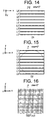
- Step R5 the backprojected line data Df on the projection plane pp is interpolated in the line direction to generate high-density backprojected line data Dh on the projection plane pp as shown in Figure 14.
- the data density of the high-density backprojected line data Dh on the projection plane pp is 8 ⁇ 32 times the maximum number of pixels in the reconstruction plane P in the line direction. For example, if the factor is 16 and the number of pixels in the reconstruction plane P is 512 ⁇ 512, the data density is 8,192 points/line.
- Step R6 the high-density backprojected line data Dh on the projection plane pp are sampled and interpolated/extrapolated, if necessary, to generate backprojected pixel data D2 for pixels on the lines L0 ⁇ L8 on the reconstruction plane P, as shown in Figure 15.
- the high-density backprojected line data Dh are sampled and interpolated/extrapolated to generate backprojection data D2 for pixels in between the lines L0 ⁇ L8, as shown in Figure 16.
- the interpolation/extrapolation is conducted based on the backprojected pixel data D2 for pixels on the lines L0 ⁇ L8 on the reconstruction plane P to generate backprojected pixel data D2 for pixels in between the lines L0 ⁇ L8.
- Step R8 the backprojected pixel data D2 shown in Figure 16 or 22 are added on a pixel-by-pixel basis, as shown in Figure 23.
- Step R9 Steps R1 - R8 are repeated for all views needed in reconstruction of a CT image (i.e., views for 360° or for "180° + fan angle") to obtain backprojected data D3( x, y ).
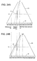
- Figure 24 is an explanatory diagram showing the relationship between a reconstruction plane P and detector rows in the multi-row detector 24.
- backprojected pixel data for a reconstruction plane P1 are generated from projection data by the detector rows 3A ⁇ 4A.
- view angle view 360°
- backprojected pixel data for the reconstruction plane P1 are generated from projection data by the detector rows 5A ⁇ 7A.
- backprojected data for the reconstruction plane P1 at views ranging over 360° are generated from projection data by the detector rows 3A ⁇ 7A.
- a CT image can be created at an image position posterior to the rectilinear motion end point Lb.
- backprojected pixel data for the reconstruction plane P4 can be generated from projection data by the detector rows 2B ⁇ 3B.
- backprojected pixel data for the reconstruction plane P4 can be generated from projection data by the detector row 1A.
- backprojected data for the reconstruction planes P1 ⁇ P4 at views ranging over 360° are generated from projection data by the detector rows 3A ⁇ 3B.
- a plurality of CT images can be created from one set of data.
- the distance of rectilinear motion in a helical scan can be reduced.
- the imaging can be reduced.
- the cycle time for reciprocal rectilinear motion can be reduced to improve temporal resolution at the same image position, and thus, the X-ray CT apparatus 100 of Example 1 is especially well-suited for perfusion CT.
- the X-ray exposure dose can be reduced.
- the technique for image reconstruction may be a conventionally known three-dimensional image reconstruction technique according to the Feldkamp method.
- three-dimensional image reconstruction techniques proposed in Japanese Patent Application Laid Open Nos. 2002-066420, 2002-147061, 2002-147231, 2002-235561, 2002-235662, 2002-267833, 2002-322756 and 2002-338947 may be employed.
- the technique for image reconstruction may be a two-dimensional image reconstruction technique.
- projection data by one detector row 2A corresponding to an image position Z1 is used.
- projection data by one detector row 4A corresponding to the image position Z1 is used.
- projection data for the detector rows 1A ⁇ 4B are used to provide all projection data for the reconstruction plane P1 at views ranging over 360°, and then a known two-dimensional image reconstruction technique can be employed to create a CT image.
- projection data by one detector row 2B is used corresponding to a reconstruction plane P4.
- projection data by one detector row 1A is used corresponding to the reconstruction plane P4.
- projection data for the detector rows 4A ⁇ 2B are used to provide all projection data for the reconstruction planes P1 ⁇ P4 at views ranging over 360°, and then a known two-dimensional image reconstruction technique can be employed to create CT images.
- a plurality of CT images can be created from one set of data.
- projection data are collected while rotating the X-ray tube 21 and multi-row detector 24 at the rectilinear motion start point La without rectilinearly moving the table 12, and a CT image is reconstructed using the collected projection data. Then, a contrast agent is injected into the subject to be imaged. This results in the CT image being changed by the contrast agent, and rectilinear motion of the table 12 is started based on the change.
- the X-ray CT apparatus of Example 4 since a range of rectilinear motion L may be defined inside the region of interest ROI, the rectilinear motion start point La can be brought closer to the center of the region of interest ROI. Thus, the change in a CT image that triggers start of the rectilinear motion can be accurately ascertained. Therefore, the X-ray CT apparatus of Example 4 is especially well-suited for Smart Prep (GE) or Real Prep (Toshiba).
- GE Smart Prep
- Toshiba Real Prep
Landscapes
- Health & Medical Sciences (AREA)
- Life Sciences & Earth Sciences (AREA)
- Engineering & Computer Science (AREA)
- Medical Informatics (AREA)
- Pathology (AREA)
- Heart & Thoracic Surgery (AREA)
- High Energy & Nuclear Physics (AREA)
- Physics & Mathematics (AREA)
- Nuclear Medicine, Radiotherapy & Molecular Imaging (AREA)
- Optics & Photonics (AREA)
- Veterinary Medicine (AREA)
- Radiology & Medical Imaging (AREA)
- Biomedical Technology (AREA)
- Biophysics (AREA)
- Molecular Biology (AREA)
- Surgery (AREA)
- Animal Behavior & Ethology (AREA)
- General Health & Medical Sciences (AREA)
- Public Health (AREA)
- Human Computer Interaction (AREA)
- Pulmonology (AREA)
- Theoretical Computer Science (AREA)
- Apparatus For Radiation Diagnosis (AREA)
Abstract
Description
- The present invention relates to an X-ray CT (computed tomography) imaging method and an X-ray CT apparatus, and more particularly to an X-ray CT imaging method and an X-ray CT apparatus by which the distance of rectilinear motion in a helical scan can be reduced.
- As shown in Figure 29, there is known an X-ray CT apparatus that ensures a constant speed of rectilinear motion in a region of interest ROI by controlling rectilinear motion of a table, the control comprising: appending an acceleration section A before a front end position Ra of the region of interest ROI for which an CT image is to be created to define a rectilinear motion start point La; appending a deceleration section B after a back end position Rb of the region of interest ROI to define a rectilinear motion end point Lb; starting rectilinear motion of the table at a table position at which an
X-ray tube 21 looks straight down on the rectilinear motion start point La; increasing the speed of rectilinear motion in the acceleration section A, driving rectilinear motion at a constant speed in the region of interest ROI and decreasing the speed of rectilinear motion in the deceleration section B; and stopping rectilinear motion at a table position at which theX-ray tube 21 looks straight down on the rectilinear motion end point Lb (see Japanese Patent Application Laid Open No. H8-173413, for example). - It should be noted that in general, the table is rectilinearly moved while rotating the
X-ray tube 21 andmulti-row detector 24 around a subject to be imaged in a helical scan, although for convenience of illustration Figure 29 represents the rectilinear motion as if it occurred without rotating theX-ray tube 21 andmulti-row detector 24. - As can be seen from Figure 29, the conventional technique appends the acceleration section A before the region of interest ROI and the deceleration section B after the region of interest ROI.
- This, however, leads to a problem that the range of rectilinear motion L is longer than the region of interest ROI. Thus, if reciprocal rectilinear motion is conducted, the cycle time becomes longer. Moreover, if X-rays are constantly emitted during rectilinear motion, the exposure dose increases.
- It is therefore an object of the present invention to provide an X-ray CT imaging method and an X-ray CT apparatus by which the distance of rectilinear motion in a helical scan can be reduced.
- In its first aspect, the present invention provides an X-ray CT imaging method for conducting a helical scan for collecting projection data while making relative rotation of at least one of an X-ray tube and a multi-row detector around a subject to be imaged and making relative rectilinear motion of them with respect to the subject to be imaged, said method characterized in comprising: defining a rectilinear motion start point and a rectilinear motion end point within a region of interest (ROI) for which a CT image is to be created; collecting projection data from said rectilinear motion start point to said rectilinear motion end point; and producing a CT image at a desired image position in said region of interest using the collected projection data.
- As used herein, the term "relative rotation" includes: for a subject to be imaged placed in between the X-ray tube and multi-row detector, rotating at least one of the X-ray tube and multi-row detector around the subject to be imaged without rotating the subject to be imaged; rotating the subject to be imaged around its axis without rotating the X-ray tube and multi-row detector; and rotating the subject to be imaged around its axis and counter-rotating at least one of the X-ray tube and multi-row detector around the subject to be imaged.
- As used herein, the term "relative rectilinear motion" includes: for a subject to be imaged placed in between the X-ray tube and multi-row detector, rectilinearly moving the subject to be imaged (or the table on which the subject to be imaged is laid) without rectilinearly moving the X-ray tube and multi-row detector; rectilinearly moving the X-ray tube and multi-row detector without rectilinearly moving the subject to be imaged (or the table on which the subject to be imaged is laid); and rectilinearly moving the subject to be imaged (or the table on which the subject to be imaged is laid) and rectilinearly moving the X-ray tube and multi-row detector in the opposite direction.
- According to the X-ray CT imaging method in the first aspect, a rectilinear motion start point and a rectilinear motion end point are defined within a region of interest, and projection data are collected from the rectilinear motion start point to the rectilinear motion end point. When a multi-row detector is employed, the X-ray beam covers the ROI front end even if the rectilinear motion start point is defined within the region of interest because the X-ray beam thickness in the direction of rectilinear motion is large. Similarly, the X-ray beam covers the ROI back end even if the rectilinear motion end point is defined within the region of interest. Therefore, a CT image can be created at a desired image position from the front end to the back end of the region of interest using the collected projection data. At that time, the distance of rectilinear motion can be made shorter than the region of interest. Accordingly, the imaging time can be reduced. Moreover, the cycle time for reciprocal rectilinear motion can be reduced. Furthermore, the X-ray exposure dose can be reduced.
- The CT image may be created by a two-dimensional or three-dimensional image reconstruction technique.
- In its second aspect, the present invention provides the X-ray CT imaging method having the aforementioned configuration, characterized in that: said rectilinear motion start point lies inward from the ROI front end position by half or approximately half of the X-ray beam thickness in the direction of rectilinear motion.
- As used herein, "the X-ray beam thickness in the direction of rectilinear motion" refers to the X-ray beam thickness in the direction of rectilinear motion at the position of the subject to be imaged placed in between the X-ray tube and multi-row detector.
- At a position at which the X-ray tube looks straight down on the rectilinear motion start point, the X-ray beam covers the subject to be imaged anterior to the start point by half or approximately half of the X-ray beam thickness in the direction of rectilinear motion.
- According to the X-ray CT imaging method in the second aspect, the rectilinear motion start point is therefore defined inward from the ROI front end position by half or approximately half of the X-ray beam thickness in the direction of rectilinear motion.
- In its third aspect, the present invention provides the X-ray CT imaging method having the aforementioned configuration, characterized in that: said rectilinear motion end point lies inward from the ROI back end position by half or about half of the X-ray beam thickness in the direction of rectilinear motion.
- As used herein, "the X-ray beam thickness in the direction of rectilinear motion" refers to the X-ray beam thickness in the direction of rectilinear motion at the position of the subject to be imaged placed in between the X-ray tube and multi-row detector.
- At a position at which the X-ray tube looks straight down on the rectilinear motion end point, the X-ray beam covers the subject to be imaged posterior to the end point by half or approximately half of the X-ray beam thickness in the direction of rectilinear motion.
- According to the X-ray CT imaging method in the third aspect, the rectilinear motion end point is therefore defined inward from the ROI front end position by half or approximately half of the X-ray beam thickness in the direction of rectilinear motion.
- In its fourth aspect, the present invention provides an X-ray CT imaging method for conducting a helical scan for collecting projection data while making relative rotation of at least one of an X-ray tube and a multi-row detector around a subject to be imaged and making relative rectilinear motion of them with respect to the subject to be imaged, said method characterized in comprising: collecting projection data from a rectilinear motion start point to a rectilinear motion end point; and creating a CT image at a desired image position in a region of interest (ROI) from an ROI front end position anterior to said rectilinear motion start point to an ROI back end position posterior to said rectilinear motion end point using the collected projection data.
- As used herein, the phrase "relative rotation" includes: for a subject to be imaged placed in between the X-ray tube and multi-row detector, rotating at least one of the X-ray tube and multi-row detector around the subject to be imaged without rotating the subject to be imaged; rotating the subject to be imaged around its axis without rotating the X-ray tube and multi-row detector; and rotating the subject to be imaged around its axis and counter-rotating at least one of the X-ray tube and multi-row detector around the subject to be imaged.
- As used herein, the phrase "relative rectilinear motion" includes: for a subject to be imaged placed in between the X-ray tube and multi-row detector, rectilinearly moving the subject to be imaged (or the table on which the subject to be imaged is laid) without rectilinearly moving the X-ray tube and multi-row detector; rectilinearly moving the X-ray tube and multi-row detector without rectilinearly moving the subject to be imaged (or the table on which the subject to be imaged is laid); and rectilinearly moving the subject to be imaged (or the table on which the subject to be imaged is laid) and rectilinearly moving the X-ray tube and multi-row detector in the opposite direction.
- According to the X-ray CT imaging method in the fourth aspect, the ROI front end is defined anterior to the rectilinear motion start point, the ROI back end is defined posterior to the rectilinear motion end point, and projection data are collected from the rectilinear motion start point to the rectilinear motion end point. When a multi-row detector is employed, the X-ray beam covers the ROI front end even if the ROI front end is defined anterior to the rectilinear motion start point because the X-ray beam thickness in the direction of rectilinear motion is large. Similarly, the X-ray beam covers the ROI back end even if the ROI back end is defined posterior to the rectilinear motion end point. Therefore, a CT image can be created at a desired image position from the ROI front end to the ROI back end using the collected projection data. At that time, the distance of rectilinear motion can be made shorter than the region of interest. Accordingly, the imaging time can be reduced. Moreover, the cycle time for reciprocal rectilinear motion can be reduced. Furthermore, the X-ray exposure dose can be reduced.
- In its fifth aspect, the present invention provides the X-ray CT imaging method having the aforementioned configuration, characterized in that: said ROI front end position lies anterior to said rectilinear motion start point by half or approximately half of the X-ray beam thickness in the direction of rectilinear motion.
- As used herein, "the X-ray beam thickness in the direction of rectilinear motion" refers to the X-ray beam thickness in the direction of rectilinear motion at the position of the subject to be imaged placed in between the X-ray tube and multi-row detector.
- At a position at which the X-ray tube looks straight down on the rectilinear motion start point, the X-ray beam covers the subject to be imaged anterior to the start point by half or approximately half of the X-ray beam thickness in the direction of rectilinear motion.
- According to the X-ray CT imaging method in the fifth aspect, the ROI front end position is therefore defined anterior to the rectilinear motion start point by half or approximately half of the X-ray beam thickness in the direction of rectilinear motion.
- In its sixth aspect, the present invention provides the X-ray CT imaging method having the aforementioned configuration, characterized in that: said ROI back end position lies posterior to said rectilinear motion end point by half or approximately half of the X-ray beam thickness in the direction of rectilinear motion.
- As used herein, "the X-ray beam thickness in the direction of rectilinear motion" refers to the X-ray beam thickness in the direction of rectilinear motion at the position of the subject to be imaged placed in between the X-ray tube and multi-row detector.
- At a position at which the X-ray tube looks straight down on the rectilinear motion end point, the X-ray beam covers the subject to be imaged posterior to the end point by half or approximately half of the X-ray beam thickness in the direction of rectilinear motion.
- According to the X-ray CT imaging method in the sixth aspect, the ROI back end is therefore defined posterior to the rectilinear motion end point by half or approximately half of the X-ray beam thickness in the direction of rectilinear motion.
- In its seventh aspect, the present invention provides the X-ray CT imaging method having the aforementioned configuration, characterized in comprising making reciprocal relative rectilinear motion by: making motion from said rectilinear motion start point to said rectilinear motion end point; then re-defining said rectilinear motion start point and said rectilinear motion end point as a new rectilinear motion end point and a new rectilinear motion start point, respectively; and making relative rectilinear motion in an opposite direction.
- According to the X-ray CT imaging method in the seventh aspect, since the distance of rectilinear motion can be made shorter than the region of interest, the cycle time for reciprocal relative rectilinear motion can be reduced. Thus, temporal resolution at the same image position can be improved. The invention of this aspect is especially suitable for perfusion CT.
- In its eighth aspect, the present invention provides the X-ray CT imaging method having the aforementioned configuration, characterized in comprising: collecting projection data while making said relative rotation at said rectilinear motion start point without making said relative rectilinear motion; reconstructing a CT image using the collected projection data; and starting said relative rectilinear motion based on a change in said CT image.
- According to the X-ray CT imaging method of the eighth aspect, since the distance of rectilinear motion is made shorter than the region of interest, the rectilinear motion start point is brought closer to the ROI center. Thus, the change in a CT image that triggers start of relative rectilinear motion can be accurately ascertained. The invention of this aspect is especially suitable for Smart Prep (GE) or Real Prep (Toshiba).
- In its ninth aspect, the present invention provides the X-ray CT imaging method having the aforementioned configuration, characterized in comprising: creating a CT image by a three-dimensional image reconstruction technique.
- According to the X-ray CT imaging method in the ninth aspect, since image reconstruction is performed according to a three-dimensional image reconstruction technique, artifacts caused by a large cone angle are prevented.
- Known three-dimensional image reconstruction techniques include the Feldkamp method and the weighted Feldkamp method.
- In its tenth aspect, the present invention provides the X-ray CT imaging method having the aforementioned configuration, characterized in that said three-dimensional image reconstruction technique is a three-dimensional backprojection method comprising: ordering the collected projection data based on the z-position of each view and extracting projection data corresponding to one line or a plurality of parallel lines at spacings of a plurality of pixels on an image reconstruction field; generating projection line data by multiplying said projection data by a cone beam reconstruction weight; generating image-positional line data by filtering said projection line data; determining backprojected pixel data of each pixel on the reconstruction field based on said image-positional line data; and determining backprojected data by adding the backprojected pixel data on a pixel-by-pixel basis for all views used in image reconstruction.
- According to the X-ray CT imaging method in the tenth aspect, since the three-dimensional image reconstruction technique is performed as proposed in Japanese Patent Application Laid Open Nos. 2002-147231 and 2002-338947, the volume of calculation can be significantly reduced.
- In its eleventh aspect, the present invention provides an X-ray CT apparatus characterized in comprising: an X-ray tube; a multi-row detector; helical scanning means for collecting projection data while making relative rotation of at least one of said X-ray tube and said multi-row detector around a subject to be imaged and making relative rectilinear motion of them with respect to the subject to be imaged, from a rectilinear motion start point to a rectilinear motion end point defined within a region of interest (ROI) for which a CT image is to be created; and image reconstructing means for producing a CT image at a desired image position in said region of interest using the collected projection data.
- According to the X-ray CT apparatus in the eleventh aspect, the X-ray CT imaging method in the first aspect is suitably implemented.
- In its twelfth aspect, the present invention provides the X-ray CT apparatus having the aforementioned configuration, characterized in that: said rectilinear motion start point lies inward from the ROI front end position by half or approximately half of the X-ray beam thickness in the direction of rectilinear motion.
- According to the X-ray CT apparatus in the twelfth aspect, the X-ray CT imaging method in the second aspect is suitably implemented.
- In its thirteenth aspect, the present invention provides the X-ray CT apparatus having the aforementioned configuration, characterized in that: said rectilinear motion end point lies inward from the ROI back end position by half or about half of the X-ray beam thickness in the direction of rectilinear motion.
- According to the X-ray CT apparatus in the thirteenth aspect, the X-ray CT imaging method in the third aspect is suitably implemented.
- In its fourteenth aspect, the present invention provides an X-ray CT apparatus characterized in comprising: an X-ray tube; a multi-row detector; helical scanning means for collecting projection data from a rectilinear motion start point to a rectilinear motion end point while making relative rotation of at least one of said X-ray tube and said multi-row detector around a subject to be imaged and making relative rectilinear motion of them with respect to the subject to be imaged; and image reconstructing means for creating a CT image at a desired image position in a region of interest (ROI) from an ROI front end position anterior to said rectilinear motion start point to an ROI back end position posterior to said rectilinear motion end point using the collected projection data.
- According to the X-ray CT apparatus in the fourteenth aspect, the X-ray CT imaging method in the fourth aspect is suitably implemented.
- In its fifteenth aspect, the present invention provides the X-ray CT apparatus having the aforementioned configuration, characterized in that: said ROI front end position lies anterior to said rectilinear motion start point by half or approximately half of the X-ray beam thickness in the direction of rectilinear motion.
- According to the X-ray CT apparatus in the fifteenth aspect, the X-ray CT imaging method in the fifth aspect is suitably implemented.
- In its sixteenth aspect, the present invention provides the X-ray CT apparatus having the aforementioned configuration, characterized in that: said ROI back end position lies posterior to said rectilinear motion end point by half or approximately half of the X-ray beam thickness in the direction of rectilinear motion.
- According to the X-ray CT apparatus in the sixteenth aspect, the X-ray CT imaging method in the sixth aspect is suitably implemented.
- In its seventeenth aspect, the present invention provides the X-ray CT apparatus having the aforementioned configuration, characterized in that said helical scanning means collects the projection data while making reciprocal relative rectilinear motion by: making motion from said rectilinear motion start point to said rectilinear motion end point; then re-defining said rectilinear motion start point and said rectilinear motion end point as a new rectilinear motion end point and a new rectilinear motion start point, respectively; and making relative rectilinear motion in an opposite direction.
- According to the X-ray CT apparatus in the seventeenth aspect, the X-ray CT imaging method in the seventh aspect is suitably implemented.
- In its eighteenth aspect, the present invention provides the X-ray CT apparatus having the aforementioned configuration, characterized in that: said helical scanning means collects projection data while making said relative rotation at said rectilinear motion start point without making said relative rectilinear motion; reconstructs a CT image using the collected projection data; and starts said relative rectilinear motion based on a change in said CT image.
- According to the X-ray CT apparatus in the eighteenth aspect, the X-ray CT imaging method in the eighth aspect is suitably implemented.
- In its nineteenth aspect, the present invention provides the X-ray CT apparatus having the aforementioned configuration, characterized in that: said image reconstructing means creates a CT image by a three-dimensional image reconstruction technique.
- According to the X-ray CT apparatus in the nineteenth aspect, the X-ray CT imaging method in the ninth aspect is suitably implemented.
- In its twentieth aspect, the present invention provides the X-ray CT apparatus having the aforementioned configuration, characterized in that: said three-dimensional image reconstruction technique is a three-dimensional backprojection method comprising: ordering the collected projection data based on the z-position of each view and extracting projection data corresponding to one line or a plurality of parallel lines at spacings of a plurality of pixels on an image reconstruction field; generating projection line data by multiplying said projection data by a cone beam reconstruction weight; generating image-positional line data by filtering said projection line data; determining backprojected pixel data of each pixel on the reconstruction field based on said image-positional line data; and determining backprojected data by adding the backprojected pixel data on a pixel-by-pixel basis for all views used in image reconstruction.
- According to the X-ray CT apparatus in the twentieth aspect, the X-ray CT imaging method in the tenth aspect is suitably implemented.
- According to the X-ray CT imaging method and X-ray CT apparatus of the present invention, the distance of rectilinear motion in a helical scan can be reduced. Thus, the cycle time for reciprocal rectilinear motion can be reduced. Moreover, the X-ray exposure dose can be reduced even if X-rays are constantly emitted during rectilinear motion.
- The X-ray CT imaging method and X-ray CT apparatus of the present invention can be employed in, for example, perfusion CT.
- Further objects and advantages of the present invention will be apparent from the following description of the preferred embodiments of the invention as illustrated in the accompanying drawings, in which:
- Figure 1 is a block diagram showing the configuration of an X-ray CT apparatus of Example 1.
- Figure 2 is an explanatory diagram showing a rotation of an X-ray tube and a multi-row detector.
- Figure 3 is an explanatory diagram showing an X-ray beam (cone beam).
- Figure 4 is a flow chart showing the general operation of the X-ray CT apparatus of Example 1.
- Figure 5 is an explanatory diagram showing a data structure.
- Figure 6 is a flow chart showing details of data collection processing of Example 1.
- Figure 7 is an explanatory diagram showing a region of interest and a range of rectilinear motion of Example 1.
- Figure 8 is a flow chart showing details of three-dimensional image reconstruction processing.
- Figure 9 is a conceptual diagram showing lines on a reconstruction plane P projected in the direction of X-ray transmission.
- Figure 10 is a conceptual diagram showing lines on the reconstruction plane P projected onto a detector plane.
- Figure 11 is a conceptual diagram showing projection data Dr on lines on the detector plane at a view angle view = 0° projected onto a projection plane.
- Figure 12 is a conceptual diagram showing projection line data Dp obtained by multiplying the projection data Dr on the projection plane pp at the view angle view = 0° by a cone beam reconstruction weight.
- Figure 13 is a conceptual diagram showing backprojected line data Df obtained by filtering the projection line data Dp on the projection plane pp at the view angle view = 0°.
- Figure 14 is a conceptual diagram showing high density backprojected line data Dh obtained by interpolating the backprojected line data Df on the projection plane pp at the view angle view = 0°.
- Figure 15 is a conceptual diagram showing backprojected pixel data D2 obtained by developing the high density backprojected line data Dh on the projection plane pp at the view angle view = 0° over lines on a reconstruction plane.
- Figure 16 is a conceptual diagram showing backprojected pixel data D2 obtained by developing the high density backprojected line data Dh on the projection plane pp at the view angle view = 0° in between the lines on the reconstruction plane.
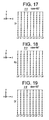
- Figure 17 is a conceptual diagram showing projection data Dr on lines on the detector plane at a view angle view = 90° projected onto a projection plane.
- Figure 18 is a conceptual diagram showing projection line data Dp obtained by multiplying the projection data Dr on the projection plane pp at the view angle view = 90° by a cone beam reconstruction weight.
- Figure 19 is a conceptual diagram showing backprojected line data Df obtained by filtering the projection line data Dp on the projection plane pp at the view angle view = 90°.
- Figure 20 is a conceptual diagram showing high density backprojected line data Dh obtained by interpolating the backprojected line data Df on the projection plane pp at the view angle view = 90°.
- Figure 21 is a conceptual diagram showing backprojected pixel data D2 obtained by developing the high density backprojected line data Dh on the projection plane pp at the view angle view = 90° over lines on a reconstruction plane.
- Figure 22 is a conceptual diagram showing backprojected pixel data D2 obtained by developing the high density backprojected line data Dh on the projection plane pp at the view angle view = 90° in between the lines on the reconstruction plane.
- Figure 23 is an explanatory diagram showing backprojected data D3 obtained by adding the backprojected pixel data D2 on a pixel-by-pixel basis for all views.
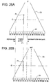
- Figure 24 is an explanatory diagram showing that a CT image can be created at an image position anterior to the rectilinear motion start point in Example 1.
- Figure 25 is an explanatory diagram showing that a plurality of CT images can be created at a plurality of image positions, respectively, from one set of data in Example 1.
- Figure 26 is an explanatory diagram showing that a CT image can be created at an image position anterior to the rectilinear motion start point in Example 3.
- Figure 27 is an explanatory diagram showing that a plurality of CT images can be created at a plurality of image positions, respectively, from one set of data in Example 3.
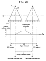
- Figure 28 is an explanatory diagram showing a region of interest and a range of rectilinear motion in Example 4.
- Figure 29 is an explanatory diagram showing a region of interest and a range of rectilinear motion in the prior art.
-
- Figure 1 is a block diagram showing the configuration of an X-ray CT apparatus 100 of Example 1.
- The X-ray CT apparatus 100 comprises an
operation console 1, atable apparatus 10, and ascan gantry 20. - The
operation console 1 comprises aninput device 2 for accepting inputs by a human operator, acentral processing apparatus 3 for executing image reconstruction processing etc., adata collection buffer 5 for collecting projection data acquired at thescan gantry 20, a CRT 6 for displaying a CT image reconstructed from the projection data, and astorage device 7 for storing programs, data, and X-ray CT images. - The
table apparatus 10 comprises a table 12 for laying thereon a subject and transporting the subject into/out of a bore (cavity portion) of thescan gantry 20. The table 12 is vertically and horizontally/rectilinearly moved by a motor incorporated in thetable apparatus 10. - The
scan gantry 20 comprises anX-ray tube 21, anX-ray controller 22, acollimator 23, amulti-row detector 24, a DAS (data acquisition system) 25, a rotator-side controller 26 for controlling theX-ray controller 22,collimator 23 andDAS 25, anoverall controller 29 for communicating control signals etc. with theoperation console 1 and imaging table 10, and aslip ring 30. - Figures 2 and 3 are explanatory diagrams of the
X-ray tube 21 andmulti-row detector 24. - The
X-ray tube 21 andmulti-row detector 24 rotate around an isocenter IC. Representing the direction of rectilinear motion of the table 12 as a z-direction, a direction perpendicular to the upper surface of the table 12 as a y-direction, and a direction orthogonal to the z- and y-directions as an x-direction, a plane of rotation of theX-ray tube 21 andmulti-row detector 24 is an x-y plane. - The
X-ray tube 21 generates an X-ray beam generally referred to as a cone beam CB. When the direction of the center axis of the cone beam CB is parallel to the y-direction, view = 0° is defined. - The
multi-row detector 24 has J (e.g., J = 256) detector rows. Each row has I (e.g., I = 1,024) channels. - Figure 4 is a flow chart showing the general operation of the X-ray CT apparatus 100.
- At Step S1, projection data D0(z, view, j, i) represented by the rectilinear motion position z, view angle view, detector row index j and channel index i is collected while rotating the
X-ray tube 21 andmulti-row detector 24 around the subject to be imaged and rectilinearly moving the table 12. The rectilinear motion position z is obtained by an encoder counting a z-position pulse, converted into a z-coordinate at theoverall controller 29, passed via theslip ring 30, and appended as z-coordinate information to the projection data from theDAS 25. - Figure 5 shows a format of the projection data at a certain view appended with the z-coordinate information.
- The data collection processing at Step S1 will be discussed later with reference to Figure 6.
- At Step S2, the projection data D0(z, view, j, i) is subjected to pre-processing (offset correction, log correction, X-ray dose correction and sensitivity correction).
- At Step S3, the pre-processed projection data D0(z, view, j, i) is filtered. Specifically, the data is subjected to Fourier transformation, multiplied by a filter (reconstruction function), and then subjected to inverse Fourier transformation.
- At Step S4, the filtered projection data D0(z, view, j, i) is subjected to three-dimensional backprojection processing to determine backprojected data D3(x, y).
- The three-dimensional backprojection processing at Step S4 will be discussed later with reference to Figure 8.
- At Step S5, the backprojected data D3(x, y) is subjected to post-processing to obtain a CT image.
- Figure 6 is a flow chart showing details of the data collection processing (Step S1 in Figure 4).
- At Step A1, the
X-ray tube 21 andmulti-row detector 24 are rotated around the subject to be imaged. - At Step A2, the table 12 is rectilinearly moved at a low speed up to a rectilinear motion start point La shown in Figure 7. The rectilinear motion start point La is defined inward from the ROI front end Ra by half or approximately half of the X-ray beam thickness w in the direction of rectilinear motion at the center of rotation IC.
- At Step A3, the direction of rectilinear motion of the table 12 is defined as a forward direction (+z-direction here).
- At Step A4, the speed of rectilinear motion of the table 12 is accelerated based on a predefined function. Moreover, the tube current is increased accordingly. The predefined function may be linear or non-linear versus time. Since the X-ray density in the direction of rectilinear motion, i.e., the amount of X-rays per unit thickness, is proportional to the ratio "tube current/speed of rectilinear motion," the tube current is increased with the increase in the speed of rectilinear motion to make the ratio "tube current/speed of rectilinear motion" constant. Thus, the X-ray density in the direction of rectilinear motion can be made constant even during acceleration.
- At Step A5, projection data D0(z, view, j, i) during acceleration are collected.
- At Step A6, when the speed of rectilinear motion of the table 12 reaches a predetermined speed, the process goes to Step A7; otherwise, goes back to Step A4 to further accelerate the table 12. The predetermined speed is a maximum desired motion speed of the table 12.
- At Step A7, projection data D0(z, view, j, i) during constant-speed motion are collected while keeping the speed of rectilinear motion of the table 12 at the predetermined speed.
- At Step A8, if the table 12 reaches a constant-speed end position C shown in Figure 7, the process goes to Step A9; otherwise, goes back to Step A7 to continue the projection data collection during constant-speed motion.
- At Step A9, the speed of rectilinear motion of the table 12 is decelerated based on a predefined function. Moreover, the tube current is decreased accordingly. The predefined function may be linear or non-linear versus time. Since the X-ray density in the direction of rectilinear motion, i.e., the amount of X-rays per unit thickness, is proportional to the ratio "tube current/speed of rectilinear motion," the tube current is decreased with the decrease in the speed of rectilinear motion to make the ratio "tube current/speed of rectilinear motion" constant. Thus, the X-ray density in the direction of rectilinear motion can be made constant even during deceleration.
- At Step A10, projection data D0(z, view, j, i) during deceleration are collected.
- At Step A11, if the table 12 reaches a rectilinear motion end point Lb shown in Figure 7, the process goes to Step A12; otherwise, goes back to Step A9 to deceleratingly move the table 12. The rectilinear motion end point Lb is defined inward from the ROI back end Rb by half or approximately half of the X-ray beam thickness w in the direction of rectilinear motion at the center of rotation IC.
- At Step A12, rectilinear motion of the table 12 is stopped.
- At Step A13, if intended data collection is completed, the process is terminated; otherwise goes to Step A14.
- At Step A14, the direction of movement of the table 12 is re-defined as the opposite direction. The process then goes back to Step A4 to continue data collection. Specifically, the previous rectilinear motion end point Lb is defined as a current rectilinear motion start point, the previous rectilinear motion start point La is defined as a current rectilinear motion end point, and projection data are collected while rectilinearly moving the table 12 in the direction opposite to the previous direction.
- As can be seen from Figure 7, when the
multi-row detector 24 is employed, the X-ray beam CB covers as far as the ROI front end Ra even if the rectilinear motion start point La is defined within the region of interest ROI, because the X-ray beam thickness w in the direction of rectilinear motion is large. Similarly, the X-ray beam CB covers as far as the ROI back end Rb even if the rectilinear motion end point Lb is defined within the region of interest ROI. Therefore, a CT image can be created at a desired image position from the ROI front end Ra to the ROI back end Rb using the collected projection data. - It should be noted that if the region of interest ROI is short, the constant-speed section may be absent. In such a case, Steps A7 and A8 are skipped.
- Figure 8 is a flow chart showing details of the three-dimensional backprojection processing (Step S4 in Figure 4).
- At Step R1, one view is taken as a view of interest from among all views needed for reconstruction of a CT image for a reconstruction plane P at a desired image position.
- At Step R2, projection data Dr corresponding to a plurality of parallel lines at spacings of a plurality of pixels on the reconstruction plane P are extracted from among the projection data D0(z, view, j, i) at the view of interest.
- Figure 9 exemplarily shows a plurality of parallel lines L0 ― L8 on the reconstruction plane P.
- The number of lines is 1/64 ― 1/2 of the maximum number of pixels in the reconstruction plane in a direction orthogonal to the lines. For example, if the number of pixels in the reconstruction plane P is 512×512, the number of lines is nine.
- Moreover, the line direction is defined as the x-direction for -45° ≤ view < 45° (or a view angle range mainly including the range and also including its vicinity) and 135° ≤ view < 225° (or a view angle range mainly including the range and also including its vicinity). The line direction is defined as the y-direction for 45° ≤ view < 135° (or a view angle range mainly including the range and also including its vicinity) and 225° ≤ view < 315° (or a view angle range mainly including the range and also including its vicinity).
- Furthermore, a projection plane pp is assumed to pass through the center of rotation IC and be parallel to the lines L0 ― L8.
- Figure 10 shows lines T0 ― T8 formed by projecting the plurality of parallel lines L0 ― L8 on the reconstruction plane P onto a detector plane dp in a direction of X-ray transmission.
- The direction of X-ray transmission is determined depending upon the geometry of the
X-ray tube 21,multi-row detector 24 and lines L0 ― L8; since the position z of the projection data D0(z, view, j, i) in the direction of rectilinear motion is known, the direction of X-ray transmission can be accurately determined even for the projection data D0(z, view, j, i) during acceleration/deceleration. - The projection data Dr corresponding to the lines L0 ― L8 can be obtained by extracting projection data at the detector row j and channel i corresponding to the lines T0 ― T8 projected onto the detector plane dp.
- Now lines L0' ― L8' formed by projecting the lines T0 ― T8 onto the projection plane pp in the direction of X-ray transmission are assumed as shown in Figure 11, and the projection data Dr are developed over the lines L0' ― L8' on the projection plane pp.
- Referring again to Figure 8, at Step R3, the projection data Dr of the lines L0' ― L8' on the projection plane pp are multiplied by a cone beam reconstruction weight to generate projection line data Dp on the projection plane pp as shown in Figure 12.
- The cone beam reconstruction weight is (r1/ r0)2, where r0 is the distance from the focal spot of the
X-ray tube 21 to the j-th detector row and the i-th channel of themulti-row detector 24 corresponding to projection data Dr, and r1 is the distance from the focal spot of theX-ray tube 21 to a point on the reconstruction plane P corresponding to the projection data Dr. - At Step R4, the projection line data Dp on the projection plane pp are filtered. Specifically, the projection line data Dp on the projection plane pp are subjected to FFT, multiplied by a filter function (reconstruction function), and subjected to inverse FFT to generate image backprojected line data Df on the projection plane pp as shown in Figure 13.
- At Step R5, the backprojected line data Df on the projection plane pp is interpolated in the line direction to generate high-density backprojected line data Dh on the projection plane pp as shown in Figure 14.
- The data density of the high-density backprojected line data Dh on the projection plane pp is 8 ― 32 times the maximum number of pixels in the reconstruction plane P in the line direction. For example, if the factor is 16 and the number of pixels in the reconstruction plane P is 512×512, the data density is 8,192 points/line.
- At Step R6, the high-density backprojected line data Dh on the projection plane pp are sampled and interpolated/extrapolated, if necessary, to generate backprojected pixel data D2 for pixels on the lines L0 ― L8 on the reconstruction plane P, as shown in Figure 15.
- At Step R7, the high-density backprojected line data Dh are sampled and interpolated/extrapolated to generate backprojection data D2 for pixels in between the lines L0 ― L8, as shown in Figure 16. Alternatively, the interpolation/extrapolation is conducted based on the backprojected pixel data D2 for pixels on the lines L0 ― L8 on the reconstruction plane P to generate backprojected pixel data D2 for pixels in between the lines L0 ― L8.
- In Figures 11 ― 16, -45° ≤ view < 45° (or a view angle range mainly including the range and also including its vicinity) and 135° ≤ view < 225° (or a view angle range mainly including the range and also including its vicinity) are assumed, while Figures 17 ― 22 are applied for 45° ≤ view < 135° (or a view angle range mainly including the range and also including its vicinity) and 225° ≤ view < 315° (or a view angle range mainly including the range and also including its vicinity).
- Referring again to Figure 8, at Step R8, the backprojected pixel data D2 shown in Figure 16 or 22 are added on a pixel-by-pixel basis, as shown in Figure 23.
- At Step R9, Steps R1 - R8 are repeated for all views needed in reconstruction of a CT image (i.e., views for 360° or for "180° + fan angle") to obtain backprojected data D3(x, y).
- Figure 24 is an explanatory diagram showing the relationship between a reconstruction plane P and detector rows in the
multi-row detector 24. - Figure 24(a) represents a view angle view = 0°. At the view angle view = 0°, backprojected pixel data for a reconstruction plane P1 are generated from projection data by the
detector rows 3A ― 4A. - Figure 24(b) represents a view angle view = 360°. At the view angle view = 360°, backprojected pixel data for the reconstruction plane P1 are generated from projection data by the
detector rows 5A ― 7A. - Thus, backprojected data for the reconstruction plane P1 at views ranging over 360° are generated from projection data by the
detector rows 3A ― 7A. - That is, at an image position Z1 anterior to the rectilinear motion start point La, projection data for all views needed in reconstruction of a CT image can be obtained, and therefore a CT image there can be created. Likewise, a CT image can be created at an image position posterior to the rectilinear motion end point Lb.
- Figure 25 is an explanatory view showing that CT images for reconstruction planes P1 ― P4 at a plurality of image positions can be created from projection data acquired by the
multi-row detector 24 during one rotation from a view angle view = 0° to a view angle view = 360°. - As shown in Figure 25(a), at the view angle view = 0°, backprojected pixel data for the reconstruction plane P4 can be generated from projection data by the
detector rows 2B ― 3B. - As shown in Figure 25(b), at the view angle view = 360°, backprojected pixel data for the reconstruction plane P4 can be generated from projection data by the
detector row 1A. - Therefore, backprojected data for the reconstruction planes P1 ― P4 at views ranging over 360° are generated from projection data by the
detector rows 3A ― 3B. - That is, a plurality of CT images can be created from one set of data.
- According to the X-ray CT apparatus 100 of Example 1, the distance of rectilinear motion in a helical scan can be reduced. Thus, the imaging can be reduced. Moreover, the cycle time for reciprocal rectilinear motion can be reduced to improve temporal resolution at the same image position, and thus, the X-ray CT apparatus 100 of Example 1 is especially well-suited for perfusion CT. Furthermore, the X-ray exposure dose can be reduced.
- The technique for image reconstruction may be a conventionally known three-dimensional image reconstruction technique according to the Feldkamp method. Moreover, three-dimensional image reconstruction techniques proposed in Japanese Patent Application Laid Open Nos. 2002-066420, 2002-147061, 2002-147231, 2002-235561, 2002-235662, 2002-267833, 2002-322756 and 2002-338947 may be employed.
- The technique for image reconstruction may be a two-dimensional image reconstruction technique.
- Specifically, as shown in Figure 26(a), at a view angle view = 0°, projection data by one
detector row 2A corresponding to an image position Z1 is used. Similarly, as shown in Figure 26(b), at a view angle view = 360°, projection data by onedetector row 4A corresponding to the image position Z1 is used. Thus, projection data for thedetector rows 1A ― 4B are used to provide all projection data for the reconstruction plane P1 at views ranging over 360°, and then a known two-dimensional image reconstruction technique can be employed to create a CT image. - Figure 27 is an explanatory diagram showing that CT images for reconstruction planes P1 ― P4 at a plurality of image positions can be created from projection data acquired by the
multi-row detector 24 during one rotation from a view angle view = 0° to a view angle view = 360°. - As shown in Figure 27(a), at a view angle view = 0°, projection data by one
detector row 2B is used corresponding to a reconstruction plane P4. Similarly, as shown in Figure 27(b), at a view angle view = 360°, projection data by onedetector row 1A is used corresponding to the reconstruction plane P4. Thus, projection data for thedetector rows 4A ― 2B are used to provide all projection data for the reconstruction planes P1 ― P4 at views ranging over 360°, and then a known two-dimensional image reconstruction technique can be employed to create CT images. - That is, a plurality of CT images can be created from one set of data.
- As shown in Figure 28, projection data are collected while rotating the
X-ray tube 21 andmulti-row detector 24 at the rectilinear motion start point La without rectilinearly moving the table 12, and a CT image is reconstructed using the collected projection data. Then, a contrast agent is injected into the subject to be imaged. This results in the CT image being changed by the contrast agent, and rectilinear motion of the table 12 is started based on the change. - According to the X-ray CT apparatus of Example 4, since a range of rectilinear motion L may be defined inside the region of interest ROI, the rectilinear motion start point La can be brought closer to the center of the region of interest ROI. Thus, the change in a CT image that triggers start of the rectilinear motion can be accurately ascertained. Therefore, the X-ray CT apparatus of Example 4 is especially well-suited for Smart Prep (GE) or Real Prep (Toshiba).
Claims (10)
- An X-ray CT imaging method for conducting a helical scan for collecting projection data while making relative rotation of at least one of an X-ray tube (21) and a multi-row detector (24) around a subject to be imaged and making relative rectilinear motion of them with respect to the subject to be imaged, said method comprising the steps of:defining a relative rectilinear motion start point and a relative rectilinear motion end point within a region of interest (ROI) for which a CT image is to be created;collecting projection data from said relative rectilinear motion start point to said relative rectilinear motion end point; andproducing a CT image at a desired image position in said region of interest using the collected projection data.
- The X-ray CT imaging method of claim 1, wherein said relative rectilinear motion start point lies inward from the ROI front end position by half or approximately half of the X-ray beam thickness in the direction of rectilinear motion.
- An X-ray CT imaging method for conducting a helical scan for collecting projection data while making relative rotation of at least one of an X-ray tube (21) and a multi-row detector (24) around a subject to be imaged and making relative rectilinear motion of them with respect to the subject to be imaged, said method comprising the steps of:collecting projection data from a relative rectilinear motion start point to a relative rectilinear motion end point; andcreating a CT image at a desired image position in a region of interest (ROI) from an ROI front end position anterior to said relative rectilinear motion start point to an ROI back end position posterior to said relative rectilinear motion end point using the collected projection data.
- The X-ray CT imaging method of claim 3, wherein said ROI front end position lies anterior to said relative rectilinear motion start point by half or approximately half of the X-ray beam thickness in the direction of rectilinear motion.
- An X-ray CT apparatus (100) comprising:an X-ray tube (21);a multi-row detector (24);a helical scanning device for collecting projection data while making relative rotation of at least one of said X-ray tube (21) and said multi-row detector (24) around a subject to be imaged and making relative rectilinear motion of them with respect to the subject to be imaged, from a relative rectilinear motion start point to a relative rectilinear motion end point defined within a region of interest (ROI) for which a CT image is to be created; andan image reconstructing device (3) for producing a CT image at a desired image position in said region of interest using the collected projection data.
- The X-ray CT apparatus (100) of claim 5, wherein said relative rectilinear motion start point lies inward from the ROI front end position by half or approximately half of the X-ray beam thickness in the direction of rectilinear motion.
- The X-ray CT apparatus (100) of claim 5 or 6, wherein said relative rectilinear motion end point lies inward from the ROI back end position by half or about half of the X-ray beam thickness in the direction of rectilinear motion.
- An X-ray CT apparatus (100) comprising:an X-ray tube (21);a multi-row detector (24);a helical scanning device for collecting projection data from a relative rectilinear motion start point to a relative rectilinear motion end point while making relative rotation of at least one of said X-ray tube (21) and said multi-row detector (24) around a subject to be imaged and making relative rectilinear motion of them with respect to the subject to be imaged; andan image reconstructing device (3) for creating a CT image at a desired image position in a region of interest (ROI) from an ROI front end position anterior to said relative rectilinear motion start point to an ROI back end position posterior to said relative rectilinear motion end point using the collected projection data.
- The X-ray CT apparatus (100) of claim 8, wherein said ROI front end position lies anterior to said relative rectilinear motion start point by half or approximately half of the X-ray beam thickness in the direction of rectilinear motion.
- The X-ray CT apparatus (100) of claim 8 or 9, wherein said ROI back end position lies posterior to said relative rectilinear motion end point by half or approximately half of the X-ray beam thickness in the direction of rectilinear motion.
Applications Claiming Priority (2)
| Application Number | Priority Date | Filing Date | Title |
|---|---|---|---|
| JP2003373855A JP4342274B2 (en) | 2003-11-04 | 2003-11-04 | X-ray CT system |
| JP2003373855 | 2003-11-04 |
Publications (1)
| Publication Number | Publication Date |
|---|---|
| EP1529490A1 true EP1529490A1 (en) | 2005-05-11 |
Family
ID=34431238
Family Applications (1)
| Application Number | Title | Priority Date | Filing Date |
|---|---|---|---|
| EP04256824A Withdrawn EP1529490A1 (en) | 2003-11-04 | 2004-11-04 | X-ray ct imaging method and x-ray ct apparatus |
Country Status (5)
| Country | Link |
|---|---|
| US (1) | US7173997B2 (en) |
| EP (1) | EP1529490A1 (en) |
| JP (1) | JP4342274B2 (en) |
| KR (1) | KR20050043651A (en) |
| CN (1) | CN1614506B (en) |
Families Citing this family (16)
| Publication number | Priority date | Publication date | Assignee | Title |
|---|---|---|---|---|
| JP3930493B2 (en) * | 2004-05-17 | 2007-06-13 | ジーイー・メディカル・システムズ・グローバル・テクノロジー・カンパニー・エルエルシー | Image processing method, image processing apparatus, and X-ray CT apparatus |
| JP4739738B2 (en) | 2004-12-01 | 2011-08-03 | ジーイー・メディカル・システムズ・グローバル・テクノロジー・カンパニー・エルエルシー | Dose evaluation method and X-ray CT apparatus |
| EP1885247A1 (en) * | 2005-05-12 | 2008-02-13 | Philips Intellectual Property & Standards GmbH | Continuous computer tomography performing super-short-scans and stronger weighting of most recent data |
| JP5011482B2 (en) * | 2005-07-19 | 2012-08-29 | ジーイー・メディカル・システムズ・グローバル・テクノロジー・カンパニー・エルエルシー | X-ray CT system |
| JP4611225B2 (en) * | 2006-03-01 | 2011-01-12 | ジーイー・メディカル・システムズ・グローバル・テクノロジー・カンパニー・エルエルシー | X-ray CT system |
| JP4322894B2 (en) * | 2006-06-20 | 2009-09-02 | ジーイー・メディカル・システムズ・グローバル・テクノロジー・カンパニー・エルエルシー | X-ray CT system |
| JP5022690B2 (en) | 2006-12-11 | 2012-09-12 | ジーイー・メディカル・システムズ・グローバル・テクノロジー・カンパニー・エルエルシー | Radiography equipment |
| US8822409B2 (en) * | 2007-06-20 | 2014-09-02 | Phylogica Limited | Compositions and uses thereof for the treatment of acute respiratory distress syndrome (ARDS) and clinical disorders associated with therewith |
| JP5184834B2 (en) * | 2007-07-18 | 2013-04-17 | ジーイー・メディカル・システムズ・グローバル・テクノロジー・カンパニー・エルエルシー | X-ray CT system |
| JP5179136B2 (en) * | 2007-10-02 | 2013-04-10 | ジーイー・メディカル・システムズ・グローバル・テクノロジー・カンパニー・エルエルシー | X-ray CT system |
| JP5142664B2 (en) * | 2007-10-25 | 2013-02-13 | 株式会社東芝 | X-ray computed tomography system |
| US20090310740A1 (en) * | 2008-06-16 | 2009-12-17 | General Electric Company | Computed tomography method and system |
| JP5511189B2 (en) * | 2009-01-05 | 2014-06-04 | ジーイー・メディカル・システムズ・グローバル・テクノロジー・カンパニー・エルエルシー | Image reconstruction method and X-ray CT apparatus |
| JP5340748B2 (en) * | 2009-01-05 | 2013-11-13 | ジーイー・メディカル・システムズ・グローバル・テクノロジー・カンパニー・エルエルシー | X-ray CT system |
| DE112009005019B4 (en) * | 2009-06-30 | 2022-02-03 | Analogic Corp. | Efficient quasi-exact 3D image reconstruction algorithm for CT scanners |
| JP2013215392A (en) * | 2012-04-09 | 2013-10-24 | Toshiba Corp | X-ray diagnostic apparatus and method for controlling the x-ray diagnostic apparatus |
Citations (2)
| Publication number | Priority date | Publication date | Assignee | Title |
|---|---|---|---|---|
| US20030031290A1 (en) * | 2001-08-09 | 2003-02-13 | Naoki Sugihara | X-ray computed tomographic imaging apparatus |
| EP1382299A1 (en) * | 2002-07-15 | 2004-01-21 | GE Medical Systems Global Technology Company LLC | System and method for acquiring x-ray data |
Family Cites Families (24)
| Publication number | Priority date | Publication date | Assignee | Title |
|---|---|---|---|---|
| US5594772A (en) * | 1993-11-26 | 1997-01-14 | Kabushiki Kaisha Toshiba | Computer tomography apparatus |
| JP3168824B2 (en) * | 1994-04-30 | 2001-05-21 | 株式会社島津製作所 | X-ray CT system |
| JP2823531B2 (en) | 1995-07-31 | 1998-11-11 | 株式会社東芝 | X-ray CT system |
| JP3124254B2 (en) | 1997-07-24 | 2001-01-15 | ジーイー横河メディカルシステム株式会社 | Radiation tomography equipment |
| JP3174288B2 (en) | 1997-09-01 | 2001-06-11 | ジーイー横河メディカルシステム株式会社 | CT image creation method and X-ray CT apparatus |
| JP3977972B2 (en) * | 1999-12-13 | 2007-09-19 | ジーイー・メディカル・システムズ・グローバル・テクノロジー・カンパニー・エルエルシー | Scanning condition determination method for tomography, tomography method and X-ray CT apparatus |
| JP2001187046A (en) | 1999-12-27 | 2001-07-10 | Ge Medical Systems Global Technology Co Llc | Multi-slice x-ray ct device and method for controlling the same |
| US6301325B1 (en) | 1999-12-22 | 2001-10-09 | Ge Medical Systems Global Technology Company Llc | Half-scan algorithm for use with a high speed multi-row fan beam helical detector |
| US6442228B1 (en) | 2000-04-20 | 2002-08-27 | Ge Medical Systems Global Technology Company, Llc | Data acquisition modifications for improved reconstruction with conventional CT |
| US6539074B1 (en) | 2000-08-25 | 2003-03-25 | General Electric Company | Reconstruction of multislice tomographic images from four-dimensional data |
| JP2002066420A (en) | 2000-08-31 | 2002-03-05 | Toppan Printing Co Ltd | Slot die head for easy product change |
| JP2002095655A (en) * | 2000-09-26 | 2002-04-02 | Shimadzu Corp | CT device |
| JP4652555B2 (en) | 2000-11-10 | 2011-03-16 | イビデン株式会社 | Catalytic converter, holding sealing material for catalytic converter |
| JP3458100B2 (en) | 2000-11-17 | 2003-10-20 | 繁雄 小川 | Snow eaves prevention device |
| JP3942142B2 (en) | 2000-12-15 | 2007-07-11 | ジーイー・メディカル・システムズ・グローバル・テクノロジー・カンパニー・エルエルシー | Radiation tomography apparatus and method |
| US6463118B2 (en) | 2000-12-29 | 2002-10-08 | Ge Medical Systems Global Technology Company, Llc | Computed tomography (CT) weighting for high quality image recontruction |
| JP2002235561A (en) | 2001-02-08 | 2002-08-23 | Denso Corp | Throttle valve adjustment device |
| JP2002235662A (en) | 2001-02-08 | 2002-08-23 | Matsushita Refrig Co Ltd | Vibration type compressor |
| JP2002267833A (en) | 2001-03-14 | 2002-09-18 | Toray Ind Inc | A method for manufacturing a color filter for a liquid crystal display. |
| JP2002322756A (en) | 2001-04-27 | 2002-11-08 | Sekisui Chem Co Ltd | Roof structure, method of constructing the roof structure, and roof panel used for the roof structure |
| JP2002338947A (en) | 2001-05-15 | 2002-11-27 | Hitachi Kasei Polymer Co Ltd | One-package sealant |
| JP4175791B2 (en) | 2001-08-20 | 2008-11-05 | ジーイー・メディカル・システムズ・グローバル・テクノロジー・カンパニー・エルエルシー | Image generation method and X-ray CT apparatus |
| JP3870105B2 (en) | 2002-02-22 | 2007-01-17 | ジーイー・メディカル・システムズ・グローバル・テクノロジー・カンパニー・エルエルシー | Back projection method and X-ray CT apparatus |
| JP2005040582A (en) | 2003-07-07 | 2005-02-17 | Ge Medical Systems Global Technology Co Llc | X-ray ct imaging method and x-ray ct apparatus |
-
2003
- 2003-11-04 JP JP2003373855A patent/JP4342274B2/en not_active Expired - Lifetime
-
2004
- 2004-11-02 US US10/979,534 patent/US7173997B2/en not_active Expired - Lifetime
- 2004-11-03 KR KR1020040088989A patent/KR20050043651A/en not_active Withdrawn
- 2004-11-04 EP EP04256824A patent/EP1529490A1/en not_active Withdrawn
- 2004-11-04 CN CN2004100925348A patent/CN1614506B/en not_active Expired - Lifetime
Patent Citations (2)
| Publication number | Priority date | Publication date | Assignee | Title |
|---|---|---|---|---|
| US20030031290A1 (en) * | 2001-08-09 | 2003-02-13 | Naoki Sugihara | X-ray computed tomographic imaging apparatus |
| EP1382299A1 (en) * | 2002-07-15 | 2004-01-21 | GE Medical Systems Global Technology Company LLC | System and method for acquiring x-ray data |
Also Published As
| Publication number | Publication date |
|---|---|
| KR20050043651A (en) | 2005-05-11 |
| JP4342274B2 (en) | 2009-10-14 |
| CN1614506B (en) | 2011-03-30 |
| US20050094761A1 (en) | 2005-05-05 |
| CN1614506A (en) | 2005-05-11 |
| JP2005137389A (en) | 2005-06-02 |
| US7173997B2 (en) | 2007-02-06 |
Similar Documents
| Publication | Publication Date | Title |
|---|---|---|
| US7173997B2 (en) | X-ray CT imaging method and X-ray CT apparatus | |
| US7508903B2 (en) | Collimator control method and X-ray CT apparatus | |
| US7522697B2 (en) | X-ray CT apparatus | |
| US20050008116A1 (en) | X-ray CT imaging method and x-ray CT system | |
| JP2015144898A (en) | Data processing apparatus for radiation imaging | |
| JP2007236662A (en) | X-ray ct system, its x-ray ct image reconstitution method and x-ray ct image photographing method | |
| KR20070038922A (en) | Image reconstructing method and x-ray ct apparatus | |
| US20090086888A1 (en) | X-ray ct apparatus and image reconstruction method | |
| JP2001299739A (en) | Method and apparatus for selecting retrospective reconstruction parameters | |
| EP1530163A2 (en) | CT image producing method and x-ray CT apparatus | |
| JP5214110B2 (en) | X-ray CT system | |
| US7260175B2 (en) | CT image producing method and X-ray CT apparatus | |
| EP1542166B1 (en) | Three-dimension back-projection method and apparatus, and x-ray CT apparatus | |
| US7519144B2 (en) | Multi-positional CT image producing method and X-ray CT apparatus | |
| JPH11113892A (en) | Image reconstruction device | |
| JP2008125909A (en) | X-ray ct apparatus | |
| JPH09117447A (en) | Picture forming and displaying method and picture diagnostic device | |
| JPH10155788A (en) | Computer tomography equipment | |
| JP2004230030A (en) | Ultra-low X-ray CT image generation method and X-ray CT apparatus | |
| JP4884649B2 (en) | X-ray CT system | |
| JP2006034865A (en) | Image reconstruction method and x-ray ct apparatus | |
| JP2007319397A (en) | X-ray ct apparatus | |
| JP2010233616A (en) | X-ray ct apparatus |
Legal Events
| Date | Code | Title | Description |
|---|---|---|---|
| PUAI | Public reference made under article 153(3) epc to a published international application that has entered the european phase |
Free format text: ORIGINAL CODE: 0009012 |
|
| AK | Designated contracting states |
Kind code of ref document: A1 Designated state(s): AT BE BG CH CY CZ DE DK EE ES FI FR GB GR HU IE IS IT LI LU MC NL PL PT RO SE SI SK TR |
|
| AX | Request for extension of the european patent |
Extension state: AL HR LT LV MK YU |
|
| 17P | Request for examination filed |
Effective date: 20051111 |
|
| AKX | Designation fees paid |
Designated state(s): DE FR GB |
|
| 17Q | First examination report despatched |
Effective date: 20071128 |
|
| STAA | Information on the status of an ep patent application or granted ep patent |
Free format text: STATUS: THE APPLICATION IS DEEMED TO BE WITHDRAWN |
|
| 18D | Application deemed to be withdrawn |
Effective date: 20120221 |