EP1529366B1 - Method and apparatus of generating a quality indicator - Google Patents
Method and apparatus of generating a quality indicator Download PDFInfo
- Publication number
- EP1529366B1 EP1529366B1 EP03788238A EP03788238A EP1529366B1 EP 1529366 B1 EP1529366 B1 EP 1529366B1 EP 03788238 A EP03788238 A EP 03788238A EP 03788238 A EP03788238 A EP 03788238A EP 1529366 B1 EP1529366 B1 EP 1529366B1
- Authority
- EP
- European Patent Office
- Prior art keywords
- quality indicator
- bits
- mode bits
- wireless communication
- communication device
- Prior art date
- Legal status (The legal status is an assumption and is not a legal conclusion. Google has not performed a legal analysis and makes no representation as to the accuracy of the status listed.)
- Expired - Lifetime
Links
- 238000000034 method Methods 0.000 title claims abstract description 21
- 238000005259 measurement Methods 0.000 claims description 33
- 238000004891 communication Methods 0.000 claims description 15
- 230000003044 adaptive effect Effects 0.000 claims description 2
- 238000010295 mobile communication Methods 0.000 claims 1
- 230000015654 memory Effects 0.000 description 10
- 230000005540 biological transmission Effects 0.000 description 3
- 230000001413 cellular effect Effects 0.000 description 3
- 230000008569 process Effects 0.000 description 3
- 238000012986 modification Methods 0.000 description 2
- 230000004048 modification Effects 0.000 description 2
- 238000012545 processing Methods 0.000 description 2
- 230000009471 action Effects 0.000 description 1
- 230000006978 adaptation Effects 0.000 description 1
- 230000010267 cellular communication Effects 0.000 description 1
- 238000010586 diagram Methods 0.000 description 1
- 230000008520 organization Effects 0.000 description 1
- 239000000126 substance Substances 0.000 description 1
- 238000006467 substitution reaction Methods 0.000 description 1
Images

Classifications
-
- H—ELECTRICITY
- H04—ELECTRIC COMMUNICATION TECHNIQUE
- H04L—TRANSMISSION OF DIGITAL INFORMATION, e.g. TELEGRAPHIC COMMUNICATION
- H04L1/00—Arrangements for detecting or preventing errors in the information received
- H04L1/0001—Systems modifying transmission characteristics according to link quality, e.g. power backoff
- H04L1/0014—Systems modifying transmission characteristics according to link quality, e.g. power backoff by adapting the source coding
-
- H—ELECTRICITY
- H04—ELECTRIC COMMUNICATION TECHNIQUE
- H04L—TRANSMISSION OF DIGITAL INFORMATION, e.g. TELEGRAPHIC COMMUNICATION
- H04L1/00—Arrangements for detecting or preventing errors in the information received
- H04L1/0001—Systems modifying transmission characteristics according to link quality, e.g. power backoff
- H04L1/0023—Systems modifying transmission characteristics according to link quality, e.g. power backoff characterised by the signalling
- H04L1/0025—Transmission of mode-switching indication
-
- H—ELECTRICITY
- H04—ELECTRIC COMMUNICATION TECHNIQUE
- H04L—TRANSMISSION OF DIGITAL INFORMATION, e.g. TELEGRAPHIC COMMUNICATION
- H04L1/00—Arrangements for detecting or preventing errors in the information received
- H04L1/20—Arrangements for detecting or preventing errors in the information received using signal quality detector
-
- H—ELECTRICITY
- H04—ELECTRIC COMMUNICATION TECHNIQUE
- H04L—TRANSMISSION OF DIGITAL INFORMATION, e.g. TELEGRAPHIC COMMUNICATION
- H04L1/00—Arrangements for detecting or preventing errors in the information received
- H04L1/0001—Systems modifying transmission characteristics according to link quality, e.g. power backoff
- H04L1/0015—Systems modifying transmission characteristics according to link quality, e.g. power backoff characterised by the adaptation strategy
- H04L1/0016—Systems modifying transmission characteristics according to link quality, e.g. power backoff characterised by the adaptation strategy involving special memory structures, e.g. look-up tables
Definitions
- Digital communication equipment may include receivers and transmitters to transmit and receive data packets.
- the data packets may include frames of multimedia information.
- the frames may include information of audio, video and the like.
- Codecs for example, speech codecs and/or video codecs may receive frames that may include errors.
- the codecs may code/decode the multimedia frames according to a quality of a transmit/receive channel, respectively.
- a rate and/or a mode of coding/decoding may be adjusted according to the quality of the channel. The adjustment may be used to perform more accurate coding/decoding of the multimedia frames. Unfortunately, the adjustment of the rate and/or mode may not prevent the codecs from generating unreliable coded/decoded multimedia frames.
- EP 1067730 A1 A method of determining the transmission quality of a radio channel is described in EP 1067730 A1. More specifically, this reference describes a method and apparatus of measuring errors in transmitted encoded bits and generating a transmission quality indicator of a radio channel by comparing the measured errors to reference data.
- the invention provides a method of generating a quality indicator as set forth in claim 1 and a wireless communication device to provide a quality indicator as set forth in claim 4, respectively.
- the invention provides an article including a storage medium as set forth in claim 15.
- Codecs intended to be included within the scope of the present invention may include, by way of example only, an Adaptive Multi Rate (AMR) voice codec as used in GSM and UMTS cellular standards, a multi mode video codec, and the like.
- AMR Adaptive Multi Rate
- mode throughout the specification may refer to the codecs mode of operation.
- the codecs mode of operation may be a rate of coding/decoding, an algorithm of coding/decoding, a bit allocation of coding/decoding and the like.
- the transceiver 100 may comprise a receiver 300, a transmitter 400, a mode selector 180, a media coder/decoder (i.e., codec) 190 and an antenna 101.
- Receiver 300 may include a demodulator 110, a mode-decoder 120, a measuring unit 130, a memory 140 that may include a look up table (LUT) 145, a quality indicator generator (QIG) 150, a threshold generator 160 and a comparator 170.
- Transmitter 400 may include a modulator 195 and power amplifier (PA) 197.
- transceiver 100 may include a cell phone handset, a wireless handheld device, a wireless personal data assistance (PDA), a digital transceiver, and the like.
- PDA wireless personal data assistance
- the scope of the present invention is not limited in this respect, the description below will refer, by way of example only, to a transceiver of a universal mobile telecommunication system (UMTS) that may operate in a global system for mobile (GSM) cellular communication network and/or in a wideband code division multiple access (WCDMA) cellular network, and the like.
- GSM global system for mobile
- WCDMA wideband code division multiple access
- antenna 101 may receive modulated radio frequency (RF) signals, which may include data frames.
- RF radio frequency
- a data frame of GSM may include 448 coded bits of voice and 8 coded bits of mode bits.
- Receiver 300 may receive the RF signal and demodulator 110 may demodulate the RF signal and may provide, for example, coded media bits such as, for example, voice, speech, audio and video to media codec 190, if desired.
- the mode bits may be used to vary the decoding/coding mode of media codec 190 in accordance with the transmit/receive channel quality.
- a portion of a standard "3GPP TS 05.09 V8.5.0 (2001-11); Technical Specification; 3rd Generation Partnership Project; Technical Specification Group GSM/EDGE; Radio Access Network; Link Adaptation; (Release 1999)” signal may define four "legal” combinations of the coded mode bits: "00000000”; "10111010", “01011101” and "11100111", wherein the first combination may be used to set media codec 190 to its lowest rate and the last combination may be used to set media codec 190 to its highest rate.
- media codec 190 may be an audio codec, such as, for example, an AMR codec, and the like.
- mode-decoder 120 may receive the data frame and decode the coded mode bits.
- mode decoder 120 may provide mode bits to mode selector 180 and coded mode bits to measuring unit 130.
- mode selector 180 may vary the mode of media codec 190 according to the mode bits.
- media codec 190 may receive the mode bits from mode decoder 120.
- media codec 190 may vary the decoding/coding mode according to the mode bits.
- measuring unit 130 may receive, for example, four valid combinations of coded mode bits from LUT 145 and a combination of coded mode bits from mode decoder 120. Measuring unit 130 may measure an error between the valid combinations to the received combination of coded mode bits, and may store the measurement in memory 140, if desired.
- memory 140 may be a Flash memory, a read access memory (RAM), a dynamic RAM (DRAM), an erasable/programmable read only memory (ROM) and the like.
- RAM read access memory
- DRAM dynamic RAM
- ROM erasable/programmable read only memory
- LUT 145 may be included in memory 140 and, in other embodiments of the present invention, LUT 145 may be a stand-alone unit, if desired.
- QIG 150 may receive the error measurements from measuring unit 130 and may generate a quality indicator 155.
- the error measurement that may be used by QIG 150 to generate quality indictor 155 may be an error measurement having a reduced error compared to the error measurements.
- the reduced error may be a minimal error, if desired.
- QIG 150 may manipulate the selected error measurement with a quality parameter to generate quality indicator 155.
- quality indicator 155 may be used to select the mode of codec 190.
- comparator 170 may compare quality indicator 155 to a threshold that may be generated by threshold generator 160 and provide a signal to mode selector 180.
- the signal to mode selector 180 may be at one of two levels, namely, a high level ("1") or low level ("0").
- mode selector 180 may refer to the mode bits as reliable mode bits and may vary the mode of codec 190 accordingly.
- mode selector 180 may refer to the mode bits as unreliable and set the mode to a predetermined (e.g., default) mode, if desired.
- quality indicator 155 may be used in the decoding operation of media codec 190, for example, to conceal errors in voice information of the received data frame, if desired.
- codec 190 in some embodiments of the present invention may be a voice decoder.
- the voice decoder may receive a label from demodulator 110.
- the label may indicate whether the received data frame is reliable. If the received data frame is not reliable, an error concealment process may be executed. The error concealment process may extrapolate and gradually mute the voice of the decoded data frame. However, at least some unreliable data frames may be labeled as reliable frames by demodulator 110, thus causing significant artifacts in the decoded voice signal.
- quality indicator 155 may be used to filter out mislead labels by accepting a label indicating a reliable frame only if quality indicator 155 is at a high level.
- media codec 190 may encode media information.
- media codec 190 may encode speech bits of a UMTS cell phone device at a predetermined mode and may provide a data frame that may include coded speech bits and coded mode bits.
- the mode bits may be set with the quality indicator.
- modulator 195 may modulate the frame and provide a modulated RF signal to PA 197, which may transmit the modulated RF signal using antenna 101.
- the method may start with receiving a data frame that may include media bits and coded mode bits that may indicate the modes of media codec 190 (block 200).
- the received coded mode bits may be compared to a plurality of different valid combinations of coded mode bits, to provide an error measurement (block 210), if desired.
- error measurement block 210
- the number of possible combinations of the coded mode bits may depend on the codec type and the communication network standard.
- the standard requirements include using an AMR codec that may include four modes, which may be encoded into eight bits, if desired.
- the number of combinations in this example is 256, while only four of them may be valid combinations.
- the operation of block 210 may be provided to all of the combinations. More particularly, the comparison may be performed using a bit-wise XOR operation, and the result of the XOR operation may be inputted to a counter. The counter may count the "1's" output from the XOR operation. Thus, the output of the counter may indicate an error value. Furthermore, the error value may be stored in memory 140 (block 220).
- the counter output may be defined in terms of Hamming distance and, accordingly, the operation described with reference to block 210 may include measurements of the Hamming distance between the received coded mode bits and a valid combination of coded mode bits.
- an error measurement with a minimal Hamming distance of the stored error measurements may be selected (block 230).
- the selection may be performed by sequentially comparing the received coded mode bits with the stored valid combinations of coded mode bits, and receiving one error measurement at a time, if desired.
- the error measurement may be compared with a previously stored error measurement. If, for example, a current error measurement is smaller than a previously stored error measurement, then the current error measurement may be stored instead of the previously stored error measurement.
- the stored error measurement may be manipulated with at least one quality parameter, and may be set as an error value (block 240).
- the error value may be set as a quality indicator (block 250). However, in other embodiments of the present invention, the error value may be set as the quality indicator 155.
Landscapes
- Engineering & Computer Science (AREA)
- Quality & Reliability (AREA)
- Computer Networks & Wireless Communication (AREA)
- Signal Processing (AREA)
- Detection And Prevention Of Errors In Transmission (AREA)
- Mobile Radio Communication Systems (AREA)
- Crystals, And After-Treatments Of Crystals (AREA)
- Encapsulation Of And Coatings For Semiconductor Or Solid State Devices (AREA)
- Apparatuses And Processes For Manufacturing Resistors (AREA)
- General Factory Administration (AREA)
- Error Detection And Correction (AREA)
Abstract
Description
- Digital communication equipment may include receivers and transmitters to transmit and receive data packets. The data packets may include frames of multimedia information. For example, the frames may include information of audio, video and the like. Codecs, for example, speech codecs and/or video codecs may receive frames that may include errors. The codecs may code/decode the multimedia frames according to a quality of a transmit/receive channel, respectively. In some codecs, a rate and/or a mode of coding/decoding may be adjusted according to the quality of the channel. The adjustment may be used to perform more accurate coding/decoding of the multimedia frames. Unfortunately, the adjustment of the rate and/or mode may not prevent the codecs from generating unreliable coded/decoded multimedia frames.
- A method of determining the transmission quality of a radio channel is described in EP 1067730 A1. More specifically, this reference describes a method and apparatus of measuring errors in transmitted encoded bits and generating a transmission quality indicator of a radio channel by comparing the measured errors to reference data.
- Thus, there is a need to provide improved ways of adjusting coding/decoding rates and/or modes.
- In first and second aspects, the invention provides a method of generating a quality indicator as set forth in claim 1 and a wireless communication device to provide a quality indicator as set forth in claim 4, respectively. In another aspect, the invention provides an article including a storage medium as set forth in claim 15.
- The subject matter regarded as the invention is particularly pointed out and distinctly claimed in the concluding portion of the specification. The invention, however, both as to organization and method of operation, together with objects, features and advantages thereof, may best be understood by reference to the following detailed description when read with the accompanied drawings in which:
- FIG. 1 is a block diagram of a transceiver, according to an embodiment of the present invention; and
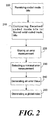
- FIG. 2 is flow chart of a method according to embodiments of the present invention.
- It will be appreciated that for simplicity and clarity of illustration, elements shown in the figures have not necessarily been drawn to scale. For example, the dimensions of some of the elements may be exaggerated relative to other elements for clarity. Further, where considered appropriate, reference numerals may be repeated among the figures to indicate corresponding or analogous elements.
- In the following detailed description, numerous specific details are set forth in order to provide a thorough understanding of the invention. However, it will be understood by those of ordinary skill in the art that the present invention may be practiced without these specific details. In other instances, well-known methods, procedures, components and circuits have not been described in detail so as not to obscure the present invention.
- Some portions of the detailed description, which follow, are presented in terms of algorithms and symbolic representations of operations on data bits or binary digital signals within a computer memory. These algorithmic descriptions and representations may be the techniques used by those skilled in the data processing arts to convey the substance of their work to others skilled in the art.
- Unless specifically stated otherwise, as apparent from the following discussions, it is appreciated that throughout the specification discussions utilizing terms such as "processing," "computing," "calculating," "determining," or the like, refer to the action and/or processes of a computer or computing system, or similar electronic computing device, that manipulate and/or transform data represented as physical, such as electronic, quantities within the computing system's registers and/or memories into other data similarly represented as physical quantities within the computing system's memories, registers or other such information storage, transmission or display devices. Furthermore, the use of the term "plurality" throughout the specification, refers to "two or more" for example, "plurality of combinations" refer to two, three, four or more combinations. In another example, "plurality of error measurements" refers to two, three, four or more error measurements.
- It should be understood that the present invention may be used in variety of applications. Although the present invention is not limited in this respect, the circuits and techniques disclosed herein may be used in many apparatuses such as codecs. Codecs intended to be included within the scope of the present invention may include, by way of example only, an Adaptive Multi Rate (AMR) voice codec as used in GSM and UMTS cellular standards, a multi mode video codec, and the like. It should be understood by one skilled in the art that the term "mode" throughout the specification may refer to the codecs mode of operation. For example, the codecs mode of operation may be a rate of coding/decoding, an algorithm of coding/decoding, a bit allocation of coding/decoding and the like.
- Turning to FIG. 1, a
transceiver 100 in accordance with an embodiment of the invention is shown. Thetransceiver 100 may comprise areceiver 300, atransmitter 400, amode selector 180, a media coder/decoder (i.e., codec) 190 and anantenna 101.Receiver 300 may include ademodulator 110, a mode-decoder 120, ameasuring unit 130, amemory 140 that may include a look up table (LUT) 145, a quality indicator generator (QIG) 150, athreshold generator 160 and acomparator 170.Transmitter 400 may include amodulator 195 and power amplifier (PA) 197. - Although the scope of the present invention is not limited to these examples,
transceiver 100 may include a cell phone handset, a wireless handheld device, a wireless personal data assistance (PDA), a digital transceiver, and the like. Although the scope of the present invention is not limited in this respect, the description below will refer, by way of example only, to a transceiver of a universal mobile telecommunication system (UMTS) that may operate in a global system for mobile (GSM) cellular communication network and/or in a wideband code division multiple access (WCDMA) cellular network, and the like. - In operation,
antenna 101 may receive modulated radio frequency (RF) signals, which may include data frames. For example, a data frame of GSM may include 448 coded bits of voice and 8 coded bits of mode bits.Receiver 300 may receive the RF signal anddemodulator 110 may demodulate the RF signal and may provide, for example, coded media bits such as, for example, voice, speech, audio and video tomedia codec 190, if desired. Although the scope of the present invention is not limited in this respect, the mode bits may be used to vary the decoding/coding mode ofmedia codec 190 in accordance with the transmit/receive channel quality. For example, a portion of a standard "3GPP TS 05.09 V8.5.0 (2001-11); Technical Specification; 3rd Generation Partnership Project; Technical Specification Group GSM/EDGE; Radio Access Network; Link Adaptation; (Release 1999)" signal, which refers to AMR voice codec, may define four "legal" combinations of the coded mode bits: "00000000"; "10111010", "01011101" and "11100111", wherein the first combination may be used to setmedia codec 190 to its lowest rate and the last combination may be used to setmedia codec 190 to its highest rate. Although the scope of the present invention is not limited in this respect,media codec 190 may be an audio codec, such as, for example, an AMR codec, and the like. - Although the scope of the present invention is not limited in this respect, mode-
decoder 120 may receive the data frame and decode the coded mode bits. In addition,mode decoder 120 may provide mode bits tomode selector 180 and coded mode bits to measuringunit 130. For example, in some embodiments of the present invention,mode selector 180 may vary the mode ofmedia codec 190 according to the mode bits. However, in other embodiments of the present invention,media codec 190 may receive the mode bits frommode decoder 120. Thus,media codec 190 may vary the decoding/coding mode according to the mode bits. - Furthermore, measuring
unit 130 may receive, for example, four valid combinations of coded mode bits fromLUT 145 and a combination of coded mode bits frommode decoder 120.Measuring unit 130 may measure an error between the valid combinations to the received combination of coded mode bits, and may store the measurement inmemory 140, if desired. Although the scope of the present invention is not limited in this respect,memory 140 may be a Flash memory, a read access memory (RAM), a dynamic RAM (DRAM), an erasable/programmable read only memory (ROM) and the like. However, it should be understood by one skilled in the art that, in some embodiments of the present invention,LUT 145 may be included inmemory 140 and, in other embodiments of the present invention,LUT 145 may be a stand-alone unit, if desired. - Although the scope of the present invention is not limited in this respect,
QIG 150 may receive the error measurements from measuringunit 130 and may generate aquality indicator 155. The error measurement that may be used byQIG 150 to generatequality indictor 155 may be an error measurement having a reduced error compared to the error measurements. For example, the reduced error may be a minimal error, if desired. Furthermore,QIG 150 may manipulate the selected error measurement with a quality parameter to generatequality indicator 155. - Although the scope of the present invention is not limited in this respect, in some embodiments of the present
invention quality indicator 155 may be used to select the mode ofcodec 190. For example,comparator 170 may comparequality indicator 155 to a threshold that may be generated bythreshold generator 160 and provide a signal tomode selector 180. Furthermore, the signal tomode selector 180 may be at one of two levels, namely, a high level ("1") or low level ("0"). For example, if the signal is high (e.g., logic value "1")mode selector 180 may refer to the mode bits as reliable mode bits and may vary the mode ofcodec 190 accordingly. However, if the signal is low (e.g., logic value "0"),mode selector 180 may refer to the mode bits as unreliable and set the mode to a predetermined (e.g., default) mode, if desired. - Furthermore, in embodiments of the present
invention quality indicator 155 may be used in the decoding operation ofmedia codec 190, for example, to conceal errors in voice information of the received data frame, if desired. - For example,
codec 190 in some embodiments of the present invention may be a voice decoder. In this example, the voice decoder may receive a label fromdemodulator 110. The label may indicate whether the received data frame is reliable. If the received data frame is not reliable, an error concealment process may be executed. The error concealment process may extrapolate and gradually mute the voice of the decoded data frame. However, at least some unreliable data frames may be labeled as reliable frames bydemodulator 110, thus causing significant artifacts in the decoded voice signal. Although the present invention is not limited in this respect,quality indicator 155 may be used to filter out mislead labels by accepting a label indicating a reliable frame only ifquality indicator 155 is at a high level. - Although the scope of the present invention is not limited in this respect,
media codec 190 may encode media information. For example,media codec 190 may encode speech bits of a UMTS cell phone device at a predetermined mode and may provide a data frame that may include coded speech bits and coded mode bits. Furthermore, in some embodiments of the present invention, the mode bits may be set with the quality indicator. Furthermore,modulator 195 may modulate the frame and provide a modulated RF signal toPA 197, which may transmit the modulated RFsignal using antenna 101. - Turning to FIG. 2 a method of generating a quality indicator according to one embodiment of the present invention is shown. The method may start with receiving a data frame that may include media bits and coded mode bits that may indicate the modes of media codec 190 (block 200). The received coded mode bits may be compared to a plurality of different valid combinations of coded mode bits, to provide an error measurement (block 210), if desired. It will be understood to the one skilled in the art that, although the scope of the invention is not limited in this respect, the number of possible combinations of the coded mode bits may depend on the codec type and the communication network standard.
- For example, in UMTS cellular networks, the standard requirements include using an AMR codec that may include four modes, which may be encoded into eight bits, if desired. Thus, the number of combinations in this example is 256, while only four of them may be valid combinations. Furthermore, the operation of
block 210 may be provided to all of the combinations. More particularly, the comparison may be performed using a bit-wise XOR operation, and the result of the XOR operation may be inputted to a counter. The counter may count the "1's" output from the XOR operation. Thus, the output of the counter may indicate an error value. Furthermore, the error value may be stored in memory 140 (block 220). - In addition, it should be understood by one skilled in the art that the counter output may be defined in terms of Hamming distance and, accordingly, the operation described with reference to block 210 may include measurements of the Hamming distance between the received coded mode bits and a valid combination of coded mode bits.
- Although the scope of the present invention is not limited in this respect, an error measurement with a minimal Hamming distance of the stored error measurements may be selected (block 230). However, in alternative embodiments of the present invention, the selection may be performed by sequentially comparing the received coded mode bits with the stored valid combinations of coded mode bits, and receiving one error measurement at a time, if desired. The error measurement may be compared with a previously stored error measurement. If, for example, a current error measurement is smaller than a previously stored error measurement, then the current error measurement may be stored instead of the previously stored error measurement. Furthermore, the stored error measurement may be manipulated with at least one quality parameter, and may be set as an error value (block 240). The error value may be set as a quality indicator (block 250). However, in other embodiments of the present invention, the error value may be set as the
quality indicator 155. - While certain features of the invention have been illustrated and described herein, many modifications, substitutions, changes, and equivalents will now occur to those skilled in the art. It is, therefore, to be understood that the appended claims are intended to cover all such modifications and changes as fall within the scope of the invention.
Claims (15)
- A method of generating a quality indicator comprising:receiving a received frame, which includes coded mode bits that are indicative of modes of a codec (190);providing a plurality of error measurements by comparing between the coded mode bits of the received frame and a plurality of valid combinations of coded mode bits to produce the plurality of error measurements;selecting an error measurement from the plurality of error measurements; andgenerating said quality indicator (155) by manipulating the selected error measurement with a quality parameter, the method characterised by:decoding a voice from voice information of the received frame; andconcealing errors in voice information of the received frame based on the quality indicator (155) by extrapolating and gradually muting the voice.
- The method of claim 1, wherein determining the plurality of error measurements comprises measuring a Hamming distance between the coded mode bits of the received frame and the plurality of valid combinations of the coded mode bits, and setting the Hamming distance as an error value.
- The method of claim 1, further comprising selecting a mode of the codec (190) according to the quality indicator (155).
- A wireless communication device (100) to provide a quality indicator (155), the device comprising:a measuring unit (130) to provide a measurement of an error in coded mode bits of a received frame;a look up table (145) to provide a plurality of valid combinations of coded mode bits to the measuring unit (130),wherein the measuring unit (130) provides a plurality of error measurements by comparing between the received coded mode bits and the valid combinations of coded mode bits and selects an error measurement from the plurality of error measurements; and a quality indicator generator (150) to generate said quality indicator (155) by manipulating the selected error measurement with a quality parameter, the wireless communication device (100) being characterised by having:a codec (190) to decode a voice from the voice information of the received data frame and to conceal errors in the voice information of the received frame based on the quality indicator (155) by extrapolating and gradually muting the voice.
- The wireless communication device (100) of claim 4, further comprising:a demodulator (110) to demodulate said received signal to provide the received frame, wherein the received frame comprises the coded mode bits and coded media bits; anda mode-decoder (120) to decode the coded mode bits to provide decoded mode bits.
- The wireless communication device (100) of claim 4, wherein the quality indicator generator (150) is able to generate the quality indicator (155) by selecting a measurement with a reduced error from a plurality of measurements provided by the measuring unit (130).
- The wireless communication device (100) of claim 4, wherein the look up table (145) is able to provide a plurality of valid combinations of coded mode bits to the measuring unit (130) and wherein the measuring unit (130) is able to measure a Hamming distance between the received mode bits and at least one of the plurality of valid combinations of coded mode bits.
- The wireless communication device (100) of claim 7, wherein the quality indicator generator (150) is able to generate the quality indicator (155) by selecting a reduced Hamming distance from the Hamming distances measured by the measuring unit (130).
- The wireless communication device (100) of claim 4 wherein the codec (190) is able to decode coded media bits of the received frame and further comprising a mode selection unit (180) that is able to select a mode of the codec (190) according to the mode bits.
- The wireless communication device (100) of claim 9 wherein the mode selection unit (180) is able to vary an encoding/decoding mode of the codec (190) if the quality indicator is below a threshold.
- The wireless communication device (100) of claim 4 wherein the codec (190) is able to decode encoded voice bits according to the quality indicator (155).
- The wireless communication device (100) of claim 4 wherein the codec (190) comprises an adaptive multi rate voice codec.
- The wireless communication device (100) of claim 5, wherein the demodulator (110) comprises a Global System for Mobile communication, GSM, decoder.
- The wireless communication device (100) of claim 5, wherein the demodulator (110) comprises a Universal Mobile Telecommunication System, UTMS, decoder.
- An article comprising a storage medium having stored thereon instructions that, when executed by a computing platform, result in performance of the method of any one of claims 1 to 3.
Applications Claiming Priority (3)
| Application Number | Priority Date | Filing Date | Title |
|---|---|---|---|
| US10/218,117 US7010731B2 (en) | 2002-08-14 | 2002-08-14 | Method and apparatus of generating a quality indicator |
| US218117 | 2002-08-14 | ||
| PCT/US2003/019875 WO2004017558A1 (en) | 2002-08-14 | 2003-07-24 | Method and apparatus of generating a quality indicator |
Publications (2)
| Publication Number | Publication Date |
|---|---|
| EP1529366A1 EP1529366A1 (en) | 2005-05-11 |
| EP1529366B1 true EP1529366B1 (en) | 2007-05-30 |
Family
ID=31714497
Family Applications (1)
| Application Number | Title | Priority Date | Filing Date |
|---|---|---|---|
| EP03788238A Expired - Lifetime EP1529366B1 (en) | 2002-08-14 | 2003-07-24 | Method and apparatus of generating a quality indicator |
Country Status (8)
| Country | Link |
|---|---|
| US (1) | US7010731B2 (en) |
| EP (1) | EP1529366B1 (en) |
| CN (1) | CN100341266C (en) |
| AT (1) | ATE363782T1 (en) |
| AU (1) | AU2003258953A1 (en) |
| DE (1) | DE60314149T2 (en) |
| MY (1) | MY134910A (en) |
| WO (1) | WO2004017558A1 (en) |
Families Citing this family (5)
| Publication number | Priority date | Publication date | Assignee | Title |
|---|---|---|---|---|
| EP1422900B1 (en) * | 2001-08-31 | 2012-03-14 | Fujitsu Limited | Receiver and receiving method for cdma communication system |
| US20090098898A1 (en) * | 2007-09-24 | 2009-04-16 | Patterson Wade C | Systems and methods for communicating panic messages in wireless communication networks |
| US8296637B1 (en) | 2008-09-22 | 2012-10-23 | Marvell International Ltd. | Channel quality monitoring and method for qualifying a storage channel using an iterative decoder |
| US8392606B2 (en) | 2008-09-23 | 2013-03-05 | Synapse Wireless, Inc. | Wireless networks and methods using multiple valid network identifiers |
| US8595603B2 (en) * | 2011-03-29 | 2013-11-26 | Intel Corporation | Apparatus and methods for selective block decoding |
Family Cites Families (12)
| Publication number | Priority date | Publication date | Assignee | Title |
|---|---|---|---|---|
| US5406562A (en) * | 1993-03-05 | 1995-04-11 | Motorola, Inc. | Bit error rate estimation |
| EP0748057B1 (en) | 1993-06-21 | 2000-05-10 | Oki Electric Industry Company, Limited | Bit error counting method and counter |
| AUPM411294A0 (en) * | 1994-02-25 | 1994-03-24 | Martin Communications Pty Ltd | Evaluation of signal processor performance |
| US5936972A (en) * | 1997-06-18 | 1999-08-10 | Motorola, Inc. | Syndrome-based channel quality or message structure determiner |
| US6084904A (en) * | 1997-07-25 | 2000-07-04 | Motorola, Inc. | Method and apparatus for adjusting a power control setpoint threshold in a wireless communication system |
| US6366622B1 (en) * | 1998-12-18 | 2002-04-02 | Silicon Wave, Inc. | Apparatus and method for wireless communications |
| US6879577B2 (en) * | 1998-12-31 | 2005-04-12 | Lg Electronics Inc. | Method and apparatus for determining frame quality in mobile communication system |
| US6499060B1 (en) * | 1999-03-12 | 2002-12-24 | Microsoft Corporation | Media coding for loss recovery with remotely predicted data units |
| EP1067730A1 (en) | 1999-07-02 | 2001-01-10 | Alcatel | Determining the transmission quality of a radio channel |
| US6430395B2 (en) * | 2000-04-07 | 2002-08-06 | Commil Ltd. | Wireless private branch exchange (WPBX) and communicating between mobile units and base stations |
| US6606726B1 (en) | 2000-06-13 | 2003-08-12 | Telefonaktiebolaget L M Ericsson (Publ) | Optimization of acceptance of erroneous codewords and throughput |
| US6782497B2 (en) * | 2001-09-20 | 2004-08-24 | Koninklijke Philips Electronics N.V. | Frame error rate estimation in a receiver |
-
2002
- 2002-08-14 US US10/218,117 patent/US7010731B2/en not_active Expired - Lifetime
-
2003
- 2003-07-24 DE DE60314149T patent/DE60314149T2/en not_active Expired - Lifetime
- 2003-07-24 AU AU2003258953A patent/AU2003258953A1/en not_active Abandoned
- 2003-07-24 AT AT03788238T patent/ATE363782T1/en not_active IP Right Cessation
- 2003-07-24 EP EP03788238A patent/EP1529366B1/en not_active Expired - Lifetime
- 2003-07-24 WO PCT/US2003/019875 patent/WO2004017558A1/en not_active Ceased
- 2003-07-24 CN CNB038017679A patent/CN100341266C/en not_active Expired - Fee Related
- 2003-08-13 MY MYPI20033085A patent/MY134910A/en unknown
Non-Patent Citations (1)
| Title |
|---|
| None * |
Also Published As
| Publication number | Publication date |
|---|---|
| DE60314149T2 (en) | 2008-01-31 |
| MY134910A (en) | 2007-12-31 |
| AU2003258953A1 (en) | 2004-03-03 |
| DE60314149D1 (en) | 2007-07-12 |
| ATE363782T1 (en) | 2007-06-15 |
| US20040034821A1 (en) | 2004-02-19 |
| US7010731B2 (en) | 2006-03-07 |
| HK1074299A1 (en) | 2005-11-04 |
| CN1606844A (en) | 2005-04-13 |
| EP1529366A1 (en) | 2005-05-11 |
| CN100341266C (en) | 2007-10-03 |
| WO2004017558A1 (en) | 2004-02-26 |
Similar Documents
| Publication | Publication Date | Title |
|---|---|---|
| FI96650C (en) | Procedure and facility for sound transmission in a telecommunication system | |
| US6574247B1 (en) | Transmission system for transmitting a main signal and an auxiliary signal | |
| WO2004006599A1 (en) | System and method for robustly detecting voice and dtx modes | |
| US5497383A (en) | Error detector circuit for receiver operative to receive discretely-encoded signals | |
| US6546515B1 (en) | Method of encoding a signal | |
| JP2011120258A (en) | Transmission system with adaptive channel encoder and decoder | |
| JP2001511327A (en) | Information encoding method and apparatus using error correction and error detection | |
| US5987631A (en) | Apparatus for measuring bit error ratio using a viterbi decoder | |
| US20080140392A1 (en) | Codec mode decoding method and apparatus for adaptive multi-rate system | |
| TW201711020A (en) | Multiresolution coding and modulation system | |
| KR100270418B1 (en) | Apparatus and method for generating noise in a digital receiver | |
| US6928592B2 (en) | Communication channel accuracy measurement | |
| MXPA02003211A (en) | Methods and systems for robust frame type protection in systems employing variable bit rates. | |
| EP1529366B1 (en) | Method and apparatus of generating a quality indicator | |
| EP1603262B1 (en) | Multi-rate speech codec adaptation method | |
| KR19990001410A (en) | Quality Evaluation Apparatus for Viterbi Decoded Data Using Zero State Evaluation | |
| AU2001294308B2 (en) | Apparatus and method for detecting transmitting rate of turbo decoder | |
| US6499008B2 (en) | Transceiver for selecting a source coder based on signal distortion estimate | |
| HK1074299B (en) | Method and apparatus of generating a quality indicator | |
| CN120419146A (en) | System and method for encoding physical layer header in wireless communication | |
| EP1298828A1 (en) | Method of blind transport format detection based on power transitions | |
| US7088778B2 (en) | Method and apparatus for measurement of channel transmission accuracy | |
| US7684521B2 (en) | Apparatus and method for hybrid decoding | |
| HUP0104936A2 (en) | Method and arrangement for channel coding or decoding of frame-structured information | |
| US8374295B2 (en) | Method of scaling input data and mobile device utilizing the same |
Legal Events
| Date | Code | Title | Description |
|---|---|---|---|
| PUAI | Public reference made under article 153(3) epc to a published international application that has entered the european phase |
Free format text: ORIGINAL CODE: 0009012 |
|
| 17P | Request for examination filed |
Effective date: 20050309 |
|
| AK | Designated contracting states |
Kind code of ref document: A1 Designated state(s): AT BE BG CH CY CZ DE DK EE ES FI FR GB GR HU IE IT LI LU MC NL PT RO SE SI SK TR |
|
| AX | Request for extension of the european patent |
Extension state: AL LT LV MK |
|
| REG | Reference to a national code |
Ref country code: HK Ref legal event code: DE Ref document number: 1074299 Country of ref document: HK |
|
| DAX | Request for extension of the european patent (deleted) | ||
| GRAP | Despatch of communication of intention to grant a patent |
Free format text: ORIGINAL CODE: EPIDOSNIGR1 |
|
| GRAS | Grant fee paid |
Free format text: ORIGINAL CODE: EPIDOSNIGR3 |
|
| GRAA | (expected) grant |
Free format text: ORIGINAL CODE: 0009210 |
|
| AK | Designated contracting states |
Kind code of ref document: B1 Designated state(s): AT BE BG CH CY CZ DE DK EE ES FI FR GB GR HU IE IT LI LU MC NL PT RO SE SI SK TR |
|
| PG25 | Lapsed in a contracting state [announced via postgrant information from national office to epo] |
Ref country code: CH Free format text: LAPSE BECAUSE OF FAILURE TO SUBMIT A TRANSLATION OF THE DESCRIPTION OR TO PAY THE FEE WITHIN THE PRESCRIBED TIME-LIMIT Effective date: 20070530 Ref country code: FI Free format text: LAPSE BECAUSE OF FAILURE TO SUBMIT A TRANSLATION OF THE DESCRIPTION OR TO PAY THE FEE WITHIN THE PRESCRIBED TIME-LIMIT Effective date: 20070530 Ref country code: LI Free format text: LAPSE BECAUSE OF FAILURE TO SUBMIT A TRANSLATION OF THE DESCRIPTION OR TO PAY THE FEE WITHIN THE PRESCRIBED TIME-LIMIT Effective date: 20070530 |
|
| REG | Reference to a national code |
Ref country code: GB Ref legal event code: FG4D |
|
| REG | Reference to a national code |
Ref country code: CH Ref legal event code: EP |
|
| REG | Reference to a national code |
Ref country code: IE Ref legal event code: FG4D |
|
| REF | Corresponds to: |
Ref document number: 60314149 Country of ref document: DE Date of ref document: 20070712 Kind code of ref document: P |
|
| PG25 | Lapsed in a contracting state [announced via postgrant information from national office to epo] |
Ref country code: SE Free format text: LAPSE BECAUSE OF FAILURE TO SUBMIT A TRANSLATION OF THE DESCRIPTION OR TO PAY THE FEE WITHIN THE PRESCRIBED TIME-LIMIT Effective date: 20070830 |
|
| PG25 | Lapsed in a contracting state [announced via postgrant information from national office to epo] |
Ref country code: ES Free format text: LAPSE BECAUSE OF FAILURE TO SUBMIT A TRANSLATION OF THE DESCRIPTION OR TO PAY THE FEE WITHIN THE PRESCRIBED TIME-LIMIT Effective date: 20070910 |
|
| PG25 | Lapsed in a contracting state [announced via postgrant information from national office to epo] |
Ref country code: AT Free format text: LAPSE BECAUSE OF FAILURE TO SUBMIT A TRANSLATION OF THE DESCRIPTION OR TO PAY THE FEE WITHIN THE PRESCRIBED TIME-LIMIT Effective date: 20070530 |
|
| REG | Reference to a national code |
Ref country code: CH Ref legal event code: PL |
|
| PG25 | Lapsed in a contracting state [announced via postgrant information from national office to epo] |
Ref country code: BE Free format text: LAPSE BECAUSE OF FAILURE TO SUBMIT A TRANSLATION OF THE DESCRIPTION OR TO PAY THE FEE WITHIN THE PRESCRIBED TIME-LIMIT Effective date: 20070530 |
|
| REG | Reference to a national code |
Ref country code: HK Ref legal event code: GR Ref document number: 1074299 Country of ref document: HK |
|
| PG25 | Lapsed in a contracting state [announced via postgrant information from national office to epo] |
Ref country code: DK Free format text: LAPSE BECAUSE OF FAILURE TO SUBMIT A TRANSLATION OF THE DESCRIPTION OR TO PAY THE FEE WITHIN THE PRESCRIBED TIME-LIMIT Effective date: 20070530 Ref country code: CZ Free format text: LAPSE BECAUSE OF FAILURE TO SUBMIT A TRANSLATION OF THE DESCRIPTION OR TO PAY THE FEE WITHIN THE PRESCRIBED TIME-LIMIT Effective date: 20070530 Ref country code: BG Free format text: LAPSE BECAUSE OF FAILURE TO SUBMIT A TRANSLATION OF THE DESCRIPTION OR TO PAY THE FEE WITHIN THE PRESCRIBED TIME-LIMIT Effective date: 20070830 Ref country code: SI Free format text: LAPSE BECAUSE OF FAILURE TO SUBMIT A TRANSLATION OF THE DESCRIPTION OR TO PAY THE FEE WITHIN THE PRESCRIBED TIME-LIMIT Effective date: 20070530 Ref country code: PT Free format text: LAPSE BECAUSE OF FAILURE TO SUBMIT A TRANSLATION OF THE DESCRIPTION OR TO PAY THE FEE WITHIN THE PRESCRIBED TIME-LIMIT Effective date: 20071030 |
|
| PG25 | Lapsed in a contracting state [announced via postgrant information from national office to epo] |
Ref country code: SK Free format text: LAPSE BECAUSE OF FAILURE TO SUBMIT A TRANSLATION OF THE DESCRIPTION OR TO PAY THE FEE WITHIN THE PRESCRIBED TIME-LIMIT Effective date: 20070530 |
|
| PLBE | No opposition filed within time limit |
Free format text: ORIGINAL CODE: 0009261 |
|
| STAA | Information on the status of an ep patent application or granted ep patent |
Free format text: STATUS: NO OPPOSITION FILED WITHIN TIME LIMIT |
|
| PG25 | Lapsed in a contracting state [announced via postgrant information from national office to epo] |
Ref country code: MC Free format text: LAPSE BECAUSE OF NON-PAYMENT OF DUE FEES Effective date: 20070731 Ref country code: GR Free format text: LAPSE BECAUSE OF FAILURE TO SUBMIT A TRANSLATION OF THE DESCRIPTION OR TO PAY THE FEE WITHIN THE PRESCRIBED TIME-LIMIT Effective date: 20070831 Ref country code: IT Free format text: LAPSE BECAUSE OF FAILURE TO SUBMIT A TRANSLATION OF THE DESCRIPTION OR TO PAY THE FEE WITHIN THE PRESCRIBED TIME-LIMIT Effective date: 20070530 |
|
| 26N | No opposition filed |
Effective date: 20080303 |
|
| PG25 | Lapsed in a contracting state [announced via postgrant information from national office to epo] |
Ref country code: RO Free format text: LAPSE BECAUSE OF FAILURE TO SUBMIT A TRANSLATION OF THE DESCRIPTION OR TO PAY THE FEE WITHIN THE PRESCRIBED TIME-LIMIT Effective date: 20070530 |
|
| PG25 | Lapsed in a contracting state [announced via postgrant information from national office to epo] |
Ref country code: FR Free format text: LAPSE BECAUSE OF FAILURE TO SUBMIT A TRANSLATION OF THE DESCRIPTION OR TO PAY THE FEE WITHIN THE PRESCRIBED TIME-LIMIT Effective date: 20080125 |
|
| PG25 | Lapsed in a contracting state [announced via postgrant information from national office to epo] |
Ref country code: IE Free format text: LAPSE BECAUSE OF NON-PAYMENT OF DUE FEES Effective date: 20070724 |
|
| PG25 | Lapsed in a contracting state [announced via postgrant information from national office to epo] |
Ref country code: EE Free format text: LAPSE BECAUSE OF FAILURE TO SUBMIT A TRANSLATION OF THE DESCRIPTION OR TO PAY THE FEE WITHIN THE PRESCRIBED TIME-LIMIT Effective date: 20070530 |
|
| PG25 | Lapsed in a contracting state [announced via postgrant information from national office to epo] |
Ref country code: CY Free format text: LAPSE BECAUSE OF FAILURE TO SUBMIT A TRANSLATION OF THE DESCRIPTION OR TO PAY THE FEE WITHIN THE PRESCRIBED TIME-LIMIT Effective date: 20070530 |
|
| PG25 | Lapsed in a contracting state [announced via postgrant information from national office to epo] |
Ref country code: LU Free format text: LAPSE BECAUSE OF NON-PAYMENT OF DUE FEES Effective date: 20070724 |
|
| PG25 | Lapsed in a contracting state [announced via postgrant information from national office to epo] |
Ref country code: HU Free format text: LAPSE BECAUSE OF FAILURE TO SUBMIT A TRANSLATION OF THE DESCRIPTION OR TO PAY THE FEE WITHIN THE PRESCRIBED TIME-LIMIT Effective date: 20071201 Ref country code: TR Free format text: LAPSE BECAUSE OF FAILURE TO SUBMIT A TRANSLATION OF THE DESCRIPTION OR TO PAY THE FEE WITHIN THE PRESCRIBED TIME-LIMIT Effective date: 20070530 |
|
| PGFP | Annual fee paid to national office [announced via postgrant information from national office to epo] |
Ref country code: DE Payment date: 20121024 Year of fee payment: 10 |
|
| PGFP | Annual fee paid to national office [announced via postgrant information from national office to epo] |
Ref country code: GB Payment date: 20121024 Year of fee payment: 10 |
|
| PGFP | Annual fee paid to national office [announced via postgrant information from national office to epo] |
Ref country code: NL Payment date: 20121025 Year of fee payment: 10 |
|
| REG | Reference to a national code |
Ref country code: NL Ref legal event code: V1 Effective date: 20140201 |
|
| GBPC | Gb: european patent ceased through non-payment of renewal fee |
Effective date: 20130724 |
|
| REG | Reference to a national code |
Ref country code: DE Ref legal event code: R119 Ref document number: 60314149 Country of ref document: DE Effective date: 20140201 |
|
| PG25 | Lapsed in a contracting state [announced via postgrant information from national office to epo] |
Ref country code: DE Free format text: LAPSE BECAUSE OF NON-PAYMENT OF DUE FEES Effective date: 20140201 Ref country code: GB Free format text: LAPSE BECAUSE OF NON-PAYMENT OF DUE FEES Effective date: 20130724 Ref country code: NL Free format text: LAPSE BECAUSE OF NON-PAYMENT OF DUE FEES Effective date: 20140201 |