EP1529243B1 - Bundling strap - Google Patents
Bundling strap Download PDFInfo
- Publication number
- EP1529243B1 EP1529243B1 EP03737096A EP03737096A EP1529243B1 EP 1529243 B1 EP1529243 B1 EP 1529243B1 EP 03737096 A EP03737096 A EP 03737096A EP 03737096 A EP03737096 A EP 03737096A EP 1529243 B1 EP1529243 B1 EP 1529243B1
- Authority
- EP
- European Patent Office
- Prior art keywords
- hook
- mechanical fastener
- bundling strap
- face
- hook strip
- Prior art date
- Legal status (The legal status is an assumption and is not a legal conclusion. Google has not performed a legal analysis and makes no representation as to the accuracy of the status listed.)
- Expired - Lifetime
Links
- 239000000463 material Substances 0.000 claims description 67
- 230000013011 mating Effects 0.000 claims description 11
- 239000000758 substrate Substances 0.000 claims description 11
- 239000004744 fabric Substances 0.000 claims description 8
- 229920001169 thermoplastic Polymers 0.000 claims 1
- 239000004416 thermosoftening plastic Substances 0.000 claims 1
- 238000000034 method Methods 0.000 description 26
- 239000012141 concentrate Substances 0.000 description 12
- 229920005989 resin Polymers 0.000 description 12
- 239000011347 resin Substances 0.000 description 12
- 229920001971 elastomer Polymers 0.000 description 7
- 238000007639 printing Methods 0.000 description 7
- 239000005060 rubber Substances 0.000 description 7
- 239000004820 Pressure-sensitive adhesive Substances 0.000 description 6
- XLYOFNOQVPJJNP-UHFFFAOYSA-N water Substances O XLYOFNOQVPJJNP-UHFFFAOYSA-N 0.000 description 6
- 239000010410 layer Substances 0.000 description 5
- -1 polypropylenes Polymers 0.000 description 5
- 239000000853 adhesive Substances 0.000 description 4
- 230000001070 adhesive effect Effects 0.000 description 4
- 238000005520 cutting process Methods 0.000 description 4
- 229920000642 polymer Polymers 0.000 description 4
- GWEVSGVZZGPLCZ-UHFFFAOYSA-N titanium dioxide Inorganic materials O=[Ti]=O GWEVSGVZZGPLCZ-UHFFFAOYSA-N 0.000 description 4
- 239000004698 Polyethylene Substances 0.000 description 3
- 239000004743 Polypropylene Substances 0.000 description 3
- 238000005259 measurement Methods 0.000 description 3
- 239000000126 substance Substances 0.000 description 3
- 229920005992 thermoplastic resin Polymers 0.000 description 3
- 239000004831 Hot glue Substances 0.000 description 2
- 229920002633 Kraton (polymer) Polymers 0.000 description 2
- 239000004677 Nylon Substances 0.000 description 2
- 238000000576 coating method Methods 0.000 description 2
- 230000006835 compression Effects 0.000 description 2
- 238000007906 compression Methods 0.000 description 2
- 229920001577 copolymer Polymers 0.000 description 2
- 238000001125 extrusion Methods 0.000 description 2
- 235000013305 food Nutrition 0.000 description 2
- 238000003754 machining Methods 0.000 description 2
- 238000004519 manufacturing process Methods 0.000 description 2
- 229920001778 nylon Polymers 0.000 description 2
- 229920000573 polyethylene Polymers 0.000 description 2
- 229920001155 polypropylene Polymers 0.000 description 2
- 238000009958 sewing Methods 0.000 description 2
- 239000012815 thermoplastic material Substances 0.000 description 2
- 238000003855 Adhesive Lamination Methods 0.000 description 1
- VGGSQFUCUMXWEO-UHFFFAOYSA-N Ethene Chemical compound C=C VGGSQFUCUMXWEO-UHFFFAOYSA-N 0.000 description 1
- 229920012485 Plasticized Polyvinyl chloride Polymers 0.000 description 1
- 239000004952 Polyamide Substances 0.000 description 1
- 239000012790 adhesive layer Substances 0.000 description 1
- 238000013459 approach Methods 0.000 description 1
- 229920001400 block copolymer Polymers 0.000 description 1
- 239000011248 coating agent Substances 0.000 description 1
- 239000000110 cooling liquid Substances 0.000 description 1
- 230000000694 effects Effects 0.000 description 1
- 235000012055 fruits and vegetables Nutrition 0.000 description 1
- 238000005304 joining Methods 0.000 description 1
- 238000003475 lamination Methods 0.000 description 1
- 239000007788 liquid Substances 0.000 description 1
- 229920001684 low density polyethylene Polymers 0.000 description 1
- 239000004702 low-density polyethylene Substances 0.000 description 1
- 238000010297 mechanical methods and process Methods 0.000 description 1
- 239000000155 melt Substances 0.000 description 1
- 239000002184 metal Substances 0.000 description 1
- 239000000203 mixture Substances 0.000 description 1
- 238000004806 packaging method and process Methods 0.000 description 1
- 239000004033 plastic Substances 0.000 description 1
- 229920003023 plastic Polymers 0.000 description 1
- 239000002985 plastic film Substances 0.000 description 1
- 239000004014 plasticizer Substances 0.000 description 1
- 229920002647 polyamide Polymers 0.000 description 1
- 229920000728 polyester Polymers 0.000 description 1
- 229920000139 polyethylene terephthalate Polymers 0.000 description 1
- 239000005020 polyethylene terephthalate Substances 0.000 description 1
- 229920000098 polyolefin Polymers 0.000 description 1
- 238000012545 processing Methods 0.000 description 1
- 238000003908 quality control method Methods 0.000 description 1
- 238000010791 quenching Methods 0.000 description 1
- 230000002787 reinforcement Effects 0.000 description 1
- 230000000452 restraining effect Effects 0.000 description 1
- 230000035945 sensitivity Effects 0.000 description 1
- 239000012941 solvent-based polyurethane adhesive Substances 0.000 description 1
- 238000010561 standard procedure Methods 0.000 description 1
- 238000010408 sweeping Methods 0.000 description 1
- 238000010998 test method Methods 0.000 description 1
- 238000012360 testing method Methods 0.000 description 1
- 239000012780 transparent material Substances 0.000 description 1
- 238000012795 verification Methods 0.000 description 1
- 238000003466 welding Methods 0.000 description 1
Images


Classifications
-
- G—PHYSICS
- G03—PHOTOGRAPHY; CINEMATOGRAPHY; ANALOGOUS TECHNIQUES USING WAVES OTHER THAN OPTICAL WAVES; ELECTROGRAPHY; HOLOGRAPHY
- G03B—APPARATUS OR ARRANGEMENTS FOR TAKING PHOTOGRAPHS OR FOR PROJECTING OR VIEWING THEM; APPARATUS OR ARRANGEMENTS EMPLOYING ANALOGOUS TECHNIQUES USING WAVES OTHER THAN OPTICAL WAVES; ACCESSORIES THEREFOR
- G03B21/00—Projectors or projection-type viewers; Accessories therefor
-
- B—PERFORMING OPERATIONS; TRANSPORTING
- B65—CONVEYING; PACKING; STORING; HANDLING THIN OR FILAMENTARY MATERIAL
- B65D—CONTAINERS FOR STORAGE OR TRANSPORT OF ARTICLES OR MATERIALS, e.g. BAGS, BARRELS, BOTTLES, BOXES, CANS, CARTONS, CRATES, DRUMS, JARS, TANKS, HOPPERS, FORWARDING CONTAINERS; ACCESSORIES, CLOSURES, OR FITTINGS THEREFOR; PACKAGING ELEMENTS; PACKAGES
- B65D63/00—Flexible elongated elements, e.g. straps, for bundling or supporting articles
- B65D63/10—Non-metallic straps, tapes, or bands; Filamentary elements, e.g. strings, threads or wires; Joints between ends thereof
-
- G—PHYSICS
- G09—EDUCATION; CRYPTOGRAPHY; DISPLAY; ADVERTISING; SEALS
- G09F—DISPLAYING; ADVERTISING; SIGNS; LABELS OR NAME-PLATES; SEALS
- G09F3/00—Labels, tag tickets, or similar identification or indication means; Seals; Postage or like stamps
- G09F3/04—Labels, tag tickets, or similar identification or indication means; Seals; Postage or like stamps to be fastened or secured by the material of the label itself, e.g. by thermo-adhesion
-
- B—PERFORMING OPERATIONS; TRANSPORTING
- B65—CONVEYING; PACKING; STORING; HANDLING THIN OR FILAMENTARY MATERIAL
- B65D—CONTAINERS FOR STORAGE OR TRANSPORT OF ARTICLES OR MATERIALS, e.g. BAGS, BARRELS, BOTTLES, BOXES, CANS, CARTONS, CRATES, DRUMS, JARS, TANKS, HOPPERS, FORWARDING CONTAINERS; ACCESSORIES, CLOSURES, OR FITTINGS THEREFOR; PACKAGING ELEMENTS; PACKAGES
- B65D2203/00—Decoration means, markings, information elements, contents indicators
- B65D2203/06—Arrangements on packages concerning bar-codes
-
- B—PERFORMING OPERATIONS; TRANSPORTING
- B65—CONVEYING; PACKING; STORING; HANDLING THIN OR FILAMENTARY MATERIAL
- B65D—CONTAINERS FOR STORAGE OR TRANSPORT OF ARTICLES OR MATERIALS, e.g. BAGS, BARRELS, BOTTLES, BOXES, CANS, CARTONS, CRATES, DRUMS, JARS, TANKS, HOPPERS, FORWARDING CONTAINERS; ACCESSORIES, CLOSURES, OR FITTINGS THEREFOR; PACKAGING ELEMENTS; PACKAGES
- B65D2313/00—Connecting or fastening means
- B65D2313/02—Connecting or fastening means of hook-and-loop type
-
- Y—GENERAL TAGGING OF NEW TECHNOLOGICAL DEVELOPMENTS; GENERAL TAGGING OF CROSS-SECTIONAL TECHNOLOGIES SPANNING OVER SEVERAL SECTIONS OF THE IPC; TECHNICAL SUBJECTS COVERED BY FORMER USPC CROSS-REFERENCE ART COLLECTIONS [XRACs] AND DIGESTS
- Y10—TECHNICAL SUBJECTS COVERED BY FORMER USPC
- Y10T—TECHNICAL SUBJECTS COVERED BY FORMER US CLASSIFICATION
- Y10T24/00—Buckles, buttons, clasps, etc.
- Y10T24/15—Bag fasteners
-
- Y—GENERAL TAGGING OF NEW TECHNOLOGICAL DEVELOPMENTS; GENERAL TAGGING OF CROSS-SECTIONAL TECHNOLOGIES SPANNING OVER SEVERAL SECTIONS OF THE IPC; TECHNICAL SUBJECTS COVERED BY FORMER USPC CROSS-REFERENCE ART COLLECTIONS [XRACs] AND DIGESTS
- Y10—TECHNICAL SUBJECTS COVERED BY FORMER USPC
- Y10T—TECHNICAL SUBJECTS COVERED BY FORMER US CLASSIFICATION
- Y10T24/00—Buckles, buttons, clasps, etc.
- Y10T24/27—Buckles, buttons, clasps, etc. including readily dissociable fastener having numerous, protruding, unitary filaments randomly interlocking with, and simultaneously moving towards, mating structure [e.g., hook-loop type fastener]
- Y10T24/2708—Combined with diverse fastener
Definitions
- the present invention relates to a mechanical bundling strap which is provided with a Universal Product Code (UPC), which is self-mating and is easy to manufacture.
- UPC Universal Product Code
- UPC codes are generally preferred in that they can be more rapidly entered using bar code readers without manual entry, as with a PLU code.
- UPC codes are limited in that they must be presented on a substrate which is substantially undeformed so as not to distort the code and also present the bar code in a readable format.
- grocery items such as fruits and vegetables
- the product has a variable width.
- the most common material used to hold these products together are elastic containing, which have a variable circumference and can provide some restraining force to keep the product packaged or together.
- U.S. Patent Nos. 5 943 804; 5 913 619; 6 279 255 and 6 058 639 all propose various alternatives of providing tags which are attached or attachable to a standard rubber band used with produce, which tags can be printed with a UPC code.
- the tags are dimensionally stable and water resistant as well as tear resistant.
- the tags are described as being printable plastic sheets and it is emphasized that these tags must be nonelastomeric so as not to disrupt or distort the bar codes.
- tags can be employed with standard rubber bands, they require generally, a complicated manufacturing or manual assembly process when attached to the rubber bands. Also the tags when attached to the rubber bands are not easily dispensable or provided in a convenient form for the end user (e.g., in a roll form).
- US-A-5 733 652 describes elastic bands which can be joined together to form a wrapping strap or bundling system useable with a variety of products.
- the elastics pieces are generally joined together by a non-tacky pressure-sensitive adhesive and it is indicated that the elastic bands can be printed with various information including PLU and UPC codes.
- PLU and UPC codes In order to be functional, when the strip is printed with a UPC code the strip would need to be non-distorted during use to enable scannability. It is indicated that scannability can only be obtained if the strips are uniformly elongated along its entire length so as not to distort the UPC code. However, uniform controlled elongation is not likely to happen in ordinary use.
- US-A-5 878 520 describes an interlocking male/female strap formed generally of plastic which can be printed with a UPC or PLU code.
- the problem with this device is that it engages and is adjustable when it is engaged however is difficult to disengage by the end user in that the locking male section engages with a hole and requires a complex twisting action in order to be removed which would not be readily apparent to a casual end user.
- US-A-5 005 264 discloses a twist-tie type fastener for use with bags, food or the like.
- the metal wire is sandwiched between two strips of deformable material.
- One of the strips of deformable material is made larger and coated with a pressure-sensitive adhesive to allow the twist-tie to be engaged without a twisting action, which is described as useful for people having limited manual dexterity.
- a pressure-sensitive adhesive to allow the twist-tie to be engaged without a twisting action, which is described as useful for people having limited manual dexterity.
- the surface can be provided with a "hook and loop cloth", however, there is no indication of how this would function so that the hook and loop cloth could be self-mating.
- UPC codes could be provided on a flat back surface of the tape backing.
- US-A-5 732 495 describes a standard twist-tie however the UPC code is provided in this case by the use of a tag which is attached to the twist-tie at one end.
- the tag is a discrete element which is heat fused or adhesion bonded to itself at one end and provided with a suitable UPC marking in the body portion. This is similar to the tags used with the elastic bands discussed above and has similar problems.
- the invention relates to a mechanical fastener bundling strap comprising the features defined in claim 1.
- the strap is engagable with itself (self-mating) by use of a loop fabric or a self-mating hook mechanical fastener at another location on the bundling strap.
- the hook strip film backing is characterized preferably by a band that runs at an angle to the bar code that has a continuous zone of transparency. This zone of transparency can be linear or nonlinear and has a transparency gap of at least 250 ⁇ m and a transparency gap percentage of at least 20 percent.
- Difficulty with providing readable bar codes is encountered in the process of printing bar codes, packaging goods with the bar code readable thereon and accurately reading the bar code on the packaged goods at the point of sale.
- Many variables are involved in the process of providing acceptably readable bar codes.
- the readability of the bar code at the point of sale depends upon the quality control of the printing process.
- the bar code must be readable at each potential point of sale. Because the scanning laser device at each point of sale may "see" the bar code in its own unique way which may be different from what will be “seen” at any other similar device at any other point of sale, a tremendous difficulty is encountered because of this factor alone.
- the invention is related to a novel bundling strap which is mechanically self-mating having at least a hook strip on one face and a surface engagable with the hook strip on the same or opposite face of the bundling strap wherein a UPC code is printed or provided on the backside of the hook strip so as to be readable through the hooks.
- the hooks are extruded hook materials having a substantially continuous film backing.
- the hook elements project outwardly from the film backing in a regular array.
- the film between adjacent hooks is smooth or substantially continuously transparent at least along bands of adjacent hooks running the length of the bar code at an angle to the UPC code bars, preferably an angle of from 0 to 45 degrees.
- the film between adjacent hooks is smooth or substantially transparent along the at least one band that runs at least the length of the printed bar code, in either a linear or nonlinear manner.
- This band along its length has a transparency gap or gaps, having a width of at least 250 ⁇ m and preferably at least 300 ⁇ m, most preferably at least 400 ⁇ m and preferably a transparency gap percentage of at least 20 percent, preferably at least 30 percent.
- the film backing of the hooks, and preferably the hooks as well, are formed from a substantially transparent film resin such that the hook strip has an overall opacity of less than 50 percent, preferably less than 30 percent.
- the hook strip when provided with a printed bar code on the film side has a bar code scannability on the hook side of greater than 10, preferably greater than 50.
- the bar code can be printed directly onto the back face or film surface of the hook strip or printed onto another substrate or film which is then laminated to the back face of the hook strip preferably by standard adhesive lamination.
- Other bonding techniques could also be used with joining of a printed substrate to the hook strip provided that the technique does not substantially effect the performance of the hook elements or the readability of the bar code.
- Printing could be enhanced by coextruding a more printable layer onto the back face of the hook strip as disclosed in US-A-6 106 922 or by treating the back face of the hook strip by corona or other standard techniques.
- the opposite face of the bundling strap can be provided over all, or a portion, of its surface with a web that is engagable with the UPC code printed or provided hook strip.
- This could be another hook strip that self-mates, for example, as disclosed in US-A-6 367 128 or a standard fibrous loop type material such as a nonwoven, woven or knitted loop, which may or may not be provided with a continuous backing. If the fibrous loop or self mating hook strip is provided with a continuous backing the backing could be printed with the UPC code and laminated to the hook strip.
- the loop material or mating hook strip could be laminated by standard adhesive, heat or mechanical methods (sewing or needling) to the hook strip or an intermediate printed substrate before or after it is joined to the hook strip.
- the lamination method cannot destroy the functionality of the hook strip or destroy the readability of the UPC code, however the UPC code is provided.
- a web engagable with the hook strip can also be provided on the same face of the bundling strap as the hook strip but in a spaced apart location. In this case, the hook strip needs to be large enough to engage with the mating web and still be provided with a UPC code.
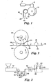
- a first method of forming hook strips with a continuous film backing is by extruding a thermoplastic resin through a die onto a continuously moving mold surface with cavities. This is generally a roll surface 10 as shown in Fig 1.
- the molten resin is extruded or forced into the cavities 12 by pressure generally by use of a nip.
- the nip is formed by the extruder die 8 and the roll 10 but alternatively the polymer could be extruded between two roll surfaces or the like.
- the nip or gap is sufficient that a film backing 30 is also formed over the cavities.
- the film backing preferably has a smooth surface along the back but could have a textured or rough surface.
- the formed material 20 has projection or hook elements 28 projecting from a film backing 30 which material is removed from the mold surface by a take-up device 18.
- a vacuum can be used to evacuate the cavities for easier extrusion into the cavities.
- the cavities 12 could be in the shape of the final hook elements as disclosed, for example, in US-A-6 174 476. In this case, a generally continuously tapered hook is pulled from continuously tapered hook cavities in its final hook form.
- the extruded strip 20 could also be a web provided with only partially formed hook elements or, as shown in Fig. 2, unformed hook elements forming projections. The tip portion 26 of these projections (or the tips of partially formed hook elements) then need to be subsequently formed into the finished hook elements 32. This would, in a preferred method, be done by deforming the tip portions under heat and pressure. The heat and pressure could be applied sequentially or simultaneously. In a preferred method, heat and pressure is selectively applied to the tip portion 26 in a nip 21.
- a nip 21 having at least one first heated surface member 22 and at least one second opposing surface member 24.
- the nip has a gap which gap has a compression zone defined by a first entry gap width and a second end gap width.
- the first gap width is substantially equal to or less than the web first average thickness.
- the second end gap width is less than the first web thickness and is the smallest gap width of the nip 21.
- the final hook strip has formed hook heads 32 on the projection 28.
- FIG. 1 A specific suitable method for forming a film having an array of upstanding projections for use in the Fig. 2 process is shown in Fig. 1.
- a feed stream of preselected thermoplastic resin is fed by conventional means into an extruder 6 which melts the resin and moves the heated resin to a die 8.
- the die 8 extrudes the resin as a wide ribbon of material onto a mold surface 10, e.g., a cylinder, having an array of mold cavities 12 in the form of elongated holes, which preferably taper to facilitate removal of the solidified resin from the mold cavities.
- These holes or mold cavities are preferably in the form of straight (i.e., only one axis in the length direction) cavities.
- the mold cavities can be connected to a vacuum system (not shown) to facilitate resin flow into the mold cavities.
- the mold cavities 12 preferably terminate in the mold surface having an open end for entry of the liquid resin and a closed end. In this case, a vacuum could be used to at least partially evacuate the mold cavities 12 prior to entering the die 8.
- the mold surface 10 preferably matches that of the die 8 where they are in contact to prevent excess resin being extruded out, e.g., the die side edges.
- the mold surface and cavities can be air or water cooled, or the like, prior to stripping the integrally formed backing and upstanding formed stems from the mold surface such as by a stripper roll 18. This provides a web 20 of a backing 30 having integrally formed upstanding stems or hooks 28 of thermoplastic material. Alternatively, upstanding stems could be formed on a preformed backing or the like by extrusion molding or other known techniques.
- the heated calender roll 22 contacts a predetermined portion of a distal end 26 of the stems 28 projecting upward from the backing 30.
- the roll temperature will be that which will readily deform the distal ends 26 under pressure created by the nips in the compression zone 38 without causing resin to stick to the roll 22 surface.
- the roll 22 surface can be treated with release coatings resistant to high temperature to allow for higher temperatures and/or longer contact times between the stem tips or distal ends 26 and the heated roll 22.
- the hooks are generally of uniform height, preferably from about 0.10 to 1.3 mm in height, and more preferably from about 0.2 to 0.5 mm in height.
- the capped stem hooks have a density on the backing preferably of from 60 to 1,600 hooks per square centimeter, and more preferably from about 100 to 700 hooks per square centimeter.
- the stem base portions have a diameter adjacent the heads of the capped stem hooks, preferably from 0.07 to 0.7 mm, and more preferably from about 0.1 to 0.3 mm.
- the capped heads project radially past the stem base portions on at least one side preferably by, on average, about 0.01 to 0.3 mm, and more preferably by, on average, about 0.02 to 0.25 mm and have average thicknesses between their outer and inner surfaces (i.e., measured in a direction parallel to the axis of the stems) preferably from about 0.01 to 0.3 mm and more preferably from about 0.02 to 0.1 mm.
- the capped heads have an average diameter (i.e., measured radially of the axis of the capped heads and the stems) to average capped head thickness ratio preferably from 1.5:1 to 12:1, and more preferably from 2.5:1 to 6:1.
- the hooks should be distributed substantially uniformly over the entire surface area of the hook strip, usually in a square, staggered or hexagonal array.
- the hooks preferably are distributed to prevent lateral slippage when engaged.
- a second method for forming a hook strip having hooks is schematically illustrated in Fig. 3.
- the method includes first extruding a strip 50 of thermoplastic resin from an extruder 51 through a die 52 having an opening cut, for example, by electron discharge machining, shaped to form the strip 50 with a base and elongate spaced ribs projecting above an upper surface of the base layer that have the cross sectional shape of the hook portions or members to be formed.
- the strip 50 is pulled around rollers 55 through a quench tank 56 filled with a cooling liquid (e.g., water), after which the ribs (but not the base layer) are transversely slit or cut at spaced locations along their lengths by a cutter 58 to form discrete portions of the ribs having lengths corresponding to about the desired thicknesses of the hook portions to be formed.
- a cooling liquid e.g., water
- the strip can be stretched prior to cutting to provide further molecular orientation to the polymers forming the ribs and/or reduce the size of the ribs and the resulting hook members formed by slitting of the ribs.
- the cutter 58 can cut using any conventional means such as reciprocating or rotating blades, lasers, or water jets, however preferably it cuts using blades oriented at an angle of about 60 to 80 degrees with respect to length of the ribs.
- the base of the strip 50 is longitudinally stretched at a stretch ratio of at least 2 to 1, and preferably at a stretch ratio of about 4 to 1, preferably between a first pair of nip rollers 60 and 61 and a second pair of nip rollers 62 and 63 driven at different surface speeds.
- the strip 50 can also be transversely stretched to provide biaxial orientation to the base.
- Roller 61 is preferably heated to heat the base prior to stretching, and the roller 62 is preferably chilled to stabilize the stretched base. Stretching causes spaces between the cut portions of the ribs, which then become the hook portions or members 74 for the completed hook fastener portion 70.
- a hook fastener portion 70 comprises a thin strong flexible film-like backing 71 having generally parallel upper and lower major surfaces 72 and 73, and a multiplicity of spaced hook members 74 projecting from at least the upper surface 72 of the backing 71.
- the backing can have planar surfaces or surface features as could be desired for tear resistance or reinforcement.
- the hook members 74 each comprise a stem portion 75 attached at one end to the backing 71 and preferably having tapered sections 76 that widen toward the backing 71 to increase the hook anchorage and breaking strengths at their junctures with the backing 71, and a head portion 77 at the end of the stem portion 75 opposite the backing 71.
- the sides 34 of the head portion 77 can be flush with the sides 35 of the stem portion 75 on two opposite sides.
- the head portion 77 has hook engaging parts or arms 36, 37 projecting past the stem portion 75 on one or both sides.
- the hook member has a rounded surface 78 opposite the stem portion 75 to help the head portion 77 enter between loops in a loop fastener portion.
- the head portion 77 also has transverse cylindrically concave surface portions 79 at the junctures between the stem portion 75 and the surfaces of the head portion 77 projecting over the backing 71.
- the backing of the hook strip should be thick enough to allow it to be attached to a substrate by a desired means such as sonic welding, heat bonding, sewing or adhesives, including pressure sensitive or hot melt adhesives, and to firmly anchor the stems.
- the hook strip backing and/or the bundling strap has a Gurley stiffness of 10 to 2000, preferably 10 to 200 so as to allow it to be rigid enough to allow the UPC code to be read without substantial deformation of the code when used either by itself or laminated to a further carrier backing structure such as a nonwoven, woven, knitted or film-type backing.
- the optimum backing thickness will vary depending upon the resin from which the hook fastener portion is made, but will generally be between 20 ⁇ m and 1000 ⁇ m, and is preferably 20 to 200 ⁇ m.
- the backing should generally be substantially nondeformable when used alone or laminated to a further substrate.
- Suitable thermoplastic materials for forming the hook strip, however formed include generally transparent polyolefins such as polypropylenes or polyethylenes, polyamides such as nylon, polyesters such as poly(ethylene terephthalate), plasticized polyvinyl chloride, copolymers and blends thereof, optionally, with other polymers or plasticizers, or the like or coextruded versions.
- polyolefins such as polypropylenes or polyethylenes
- polyamides such as nylon
- polyesters such as poly(ethylene terephthalate)
- plasticized polyvinyl chloride copolymers and blends thereof, optionally, with other polymers or plasticizers, or the like or coextruded versions.
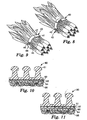
- Fig. 8 is a perspective view of a bundling strap 43 of the present invention where the hook strip is engagable with itself or a mating element provided on the same face of the bundling strap.
- a hook strip 47 is a self mating material if it engages with itself. If a mating mechanical fastener is provided on the same face of the bundling strap as the UPC code 46 provided hook strip these separate elements would typically be laminated to a common backing or carrier substrate.
- Fig. 9 is shown a more typical embodiment where the bundling strap 41 has a hook strip 47 which is engagable with a mating web 45 on the back side of the bundling strap 40.
- Fig. 10 is a depiction of a representative embodiment of a bundling strap in accordance with the present invention where a hook strip 80 having hook elements 81 is provided with a bar code printing 83 on the back side of the hook strip. This printed hook strip is then laminated by a pressure-sensitive or hot melt adhesive 82 to a loop material 85 which preferably is provided with a backing 84.
- Fig. 11 is an alternative hook strip where the hook strip 90 is laminated by an adhesive layer 91 to a substrate 97 provided with a printed bar code. This layer is then further laminated by a pressure-sensitive adhesive 93 or the like to a loop material 95 having a backing 94.
- the Opacity of the hook material webs was measured using a HunterLAB Color Quest 45/0 colorimeter (Reston, VA) using a 1 ⁇ 2" diameter opening, configured with the following settings; Scale - Hunter LAB, Procedure - Opacity (Y), Differences - DE*, Indices - ALPHA 20mm, Display mode - Absolute, Delta E Illuminate - D65, and Delta E Observer 10°.
- the hook material web was placed against the opening with the hook side toward light source.
- UPC Universal Product Code
- the ability to read a UPC (Universal Product Code) bar code through the hook material was determined using a RJS D4000 laser verification scanner (Printronix Inc. 14600 Myford Rd., Irvine, CA 92623) and the following procedure.
- the scanner "gun” was rigidly mounted 6.4 cm above a bench top.
- the hook material webs were placed on the bench top, hook side up, on top of a standard reference bar code (RJS reference sheet, part number 002-1958 Rev. B, bar code I-20F5).
- the webs were positioned such that the angle of the scanner with respect to the bench top was 80 degrees.
- the scanner "trigger” was held continuously for 5 seconds.
- the bar code is read by sweeping a small spot of light back and forth in a straight scan line, across the hook material above the bar code.
- a successful scan requires that the spot of light sweep across all black and white lines, thus the scan line must be near perpendicular to the bars of the bar code.
- the direction of the scan line was either in a y-direction (generally parallel to the machine direction of the hook material web), or an x-direction, orthogonal to the y-direction (generally parallel to the cross direction of the hook material web) as noted in Table 2 below.
- the ability to successfully scan a bar code through a hook material web depends not only upon the overall Opacity of the web, but also upon the ability of the scanner to successfully interpret the width of any individual bar in the printed bar code.
- Webs such as hook material webs, having three dimensional structures or features above a flat base, can be difficult to scan because the structures can appear opaque to the scanner, especially if the dimensions of the structures approach the width of the bars of the printed bar code. It has been found that the distance between two adjacent hook structures (the gap) affects the scannability of the printed bar code beneath. The gap appears transparent to the scanner (provided the overall Opacity is not too high), while the hook structures appear opaque to the scanner. Not all structures or topographical features will appear opaque to the scanner.
- Transparency gap is that portion of the gap which appears transparent to the scanner and is obtained in the following manner.
- a 7.6 cm by 7.6 cm hook sample was placed hook side up on a microscope stage mount equipped with a micrometer adjustment. A magnification of approximately 15x was used with the sample being lit from above. A piece of black paper was placed beneath the hook sample.
- a crosshair generator was used to align the hook perpendicular to the bar code scan direction. The microscope stage was moved to align an individual hook center with the center of the crosshair. The stage was moved perpendicular to the scan direction to the center of the next nearest hook in a 60 degree range.
- the micrometer reading was recorded and labeled as hook spacing (C n ).
- the measurement procedure was repeated except only the distance (d n ) corresponding to transparent material was measured and recorded as the transparency gap (sum of d n between a given hook spacing C n ).
- the distance d selected ignored opaque lines less than the width of standard bar codes, such as the narrow opaque lines shown in Fig. 6.
- the distance d otherwise was selected at right angles to the hook rows.
- the transparency gap was divided by the hook spacing, multiplied by 100, and recorded as percent (%) transparency gap.
- a mechanical fastener hook material web was made using the apparatus shown in Fig. 3.
- a polypropylene/polyethylene copolymer (Accpro 9117, 2.0 MFI, BP Amoco Polymers, Inc.) was extruded with a 6.35 cm single screw extruder (24:1 L/D) using a barrel temperature profile of 177°C-232°C-246°C and a die temperature of approximately 235°C.
- a white color concentrate consisting of 50% Ti02 and 50% PP/PE copolymer was added to the extruder at 0.5% by weight of the total extrudate.
- the extrudate was extruded vertically downward through a die having an opening cut by electron discharge machining.
- the extrudate After being shaped by the die, the extrudate is quenched in a water tank at a speed of 6.1 meter/min with the water being maintained at approximately 10°C.
- the web was then advanced through a cutting station where the ribs (but not the base layer) were transversely cut at an angle of 23 degrees measured from the transverse direction of the web. The spacing of the cuts was 305 microns.
- the base of the web After cutting the ribs, the base of the web was longitudinally stretched at a stretch ratio of approximately 4.1 to 1 between a first pair of nip rolls and a second pair of nip rolls to further separate the individual hook elements to approximately 8 hooks/cm. There were approximately 10 rows of ribs or cut hooks per centimeter.
- the upper roll of the first pair of nip rolls was heated to 143°C to soften the web prior to stretching.
- the general profile of this hook is depicted in Fig. 4.
- a top view of the hook material web is shown as a photomicrograph in Fig. 5.
- the transparency gap was d3 in the x-direction and the hook spacing between adjacent hooks was C 2 .
- the transparency gap was the sum of d1 and d2 in the y-direction and the hook spacing was C 1 .
- a web was prepared similar to the Hook Material web 1 except the width of the hook cap was changed by adjusting the die lip gap to adjust die pressure which affects die swell and thus affects the hook dimensions.
- White color concentrate was added at 0.25%.
- a web was prepared similar to the Hook Material web 1 except the width of the hook cap was changed by adjusting the die lip gap to adjust die pressure .
- White color concentrate was added at 0.5%.
- a web was prepared similar to the Hook Material web 1 except the width of the hook cap was changed by adjusting the die lip gap to adjust die pressure.
- White color concentrate was added at 1.0%.
- a web was prepared similar to the Hook Material web 1 except the width of the hook cap was changed by adjusting the die lip gap to adjust die pressure.
- White color concentrate was added at 0.5%.
- a web was prepared similar to the Hook Material web 1 except the width of the hook cap was changed by adjusting the die lip gap to adjust die pressure. No white color concentrate was added.
- a web was prepared similar to the Hook Material web 1 except the width of the hook cap was changed by adjusting the die lip gap to adjust die pressure.
- White color concentrate was added at 0.75%.
- a web was prepared similar to the Hook Material web 1 except the width of the hook cap was changed by adjusting the die lip gap to adjust die pressure.
- White color concentrate was added at 0.25%.
- a web was prepared similar to the Hook Material web 1 except the width of the hook cap was changed by adjusting the die lip gap to adjust die pressure.
- White color concentrate was added at 0.5%.
- a web was prepared similar to the Hook Material web 1 except the width of the hook cap was changed by adjusting the die lip gap to adjust die pressure.
- White color concentrate was added at 0.75%.
- a web was prepared similar to the Hook Material web 1 except the width of the hook cap was changed by adjusting the die lip gap to adjust die pressure.
- White color concentrate was added at 0.5%.
- a web was prepared similar to the Hook Material web 1 except the width of the hook cap was changed by adjusting the die lip gap to adjust die pressure.
- White color concentrate was added at 1.5%.
- hook material XMH-01-062 from 3M Corporation, St. Paul, MN. 217 hooks/square centimeter, 120 grams/square meter basis weight and 0% TiO2.
- a top view of the hook material web is shown as a photomicrograph in Fig. 6.
- the transparency gap in the x-direction was d4 and the hook spacing was C 3 .
- the transparency gap in the y-direction was d5 and the hook spacing was C 4 .
- the smooth non-hook side of Hook Material 13 was printed with the UPC bar code symbol using a flexographic printing process and a Multibond ink (Sun Chemical Ink, Northlake, IL).
- the bar code was printed at 125% of nominal and truncated to 1.6 cm in bar height.
- the bar code was printed such that the lines of the bar code were in the cross direction of the hook material web.
- a moisture-curable solvent-based polyurethane adhesive was coated onto the printed side of the hook material web using a gravure roll and then laminated to a nylon knitted loop fabric (Boccolina 32 grams/square meter, Sitip SpA, Bergamo, Italy). The laminate was then slit to produce 1.27 cm wide rolls of bundling straps.
- the smooth non-hook side of Hook Material 13 was printed with the UPC bar code symbol using a flexographic printing process and a Ultrabond ink (Sun Chemical Ink, Northlake, IL).
- the bar code was printed at 150% of nominal and truncated to 1.6 cm in bar height.
- the bar code was printed such that the lines of the bar code were in the cross direction of the hook material web.
- An adhesive coated knitted loop substrate (KN-2543 3M Corp. St. Paul, MN) was laminated onto the printed side of the hook material web.
- KN-2543 consists of the Boccolina fabric mentioned above, a 25 micron LDPE film on the backside of the fabric and a pressure-sensitive adhesive (50% Kraton 1107 block copolymer Kraton Polymers Inc., Houston, Texas, 50% Wingtack Plus tackifier, Goodyear Chemicals, Akron, Ohio, 27 grams/square meter coating weight) on the exposed side of the film.
- the laminate was then slit to produce 1.27 cm wide rolls of bundling straps.
- Table 1 below shows the width of the cap portion of the hooks and the spacing of the hooks on the web. The dimensions were measured in the cross-direction (CD or X) of the web except for Hook Material 5 which was also measured in the machine-direction (MD or Y) to demonstrate the directionality sensitivity of the scannability test.
- Table 2 shows the Transparency Gap measurements in both absolute numbers and as a percent, for the hook materials along with the bar code scannability. In general, as the % Transparency Gap in between the hooks increases, the ability to successfully scan a bar code increases.
Landscapes
- Engineering & Computer Science (AREA)
- Mechanical Engineering (AREA)
- Physics & Mathematics (AREA)
- General Physics & Mathematics (AREA)
- Theoretical Computer Science (AREA)
- Package Frames And Binding Bands (AREA)
- Slide Fasteners, Snap Fasteners, And Hook Fasteners (AREA)
- Wrappers (AREA)
- Packaging Of Annular Or Rod-Shaped Articles, Wearing Apparel, Cassettes, Or The Like (AREA)
Description
- The present invention relates to a mechanical bundling strap which is provided with a Universal Product Code (UPC), which is self-mating and is easy to manufacture.
- In the retail industries, particularly the grocery and food industries, it is common to provide most products with either UPC or PLU codes to allow the price to be entered at the point of sale. UPC codes are generally preferred in that they can be more rapidly entered using bar code readers without manual entry, as with a PLU code. However, UPC codes are limited in that they must be presented on a substrate which is substantially undeformed so as not to distort the code and also present the bar code in a readable format. With grocery items, such as fruits and vegetables, generally the product has a variable width. The most common material used to hold these products together are elastic containing, which have a variable circumference and can provide some restraining force to keep the product packaged or together. Generally, the most common material is an elastic or rubber band, which is wrapped around the product. These rubber bands are not susceptible to printing of UPC codes in that if they are extended and distorted the UPC code is made unreadable. However, PLU codes can be printed on the surface of a rubber band. U.S. Patent Nos. 5 943 804; 5 913 619; 6 279 255 and 6 058 639 all propose various alternatives of providing tags which are attached or attachable to a standard rubber band used with produce, which tags can be printed with a UPC code. The tags are dimensionally stable and water resistant as well as tear resistant. Generally, the tags are described as being printable plastic sheets and it is emphasized that these tags must be nonelastomeric so as not to disrupt or distort the bar codes.
- Although these tags can be employed with standard rubber bands, they require generally, a complicated manufacturing or manual assembly process when attached to the rubber bands. Also the tags when attached to the rubber bands are not easily dispensable or provided in a convenient form for the end user (e.g., in a roll form).
- US-A-5 733 652 describes elastic bands which can be joined together to form a wrapping strap or bundling system useable with a variety of products. The elastics pieces are generally joined together by a non-tacky pressure-sensitive adhesive and it is indicated that the elastic bands can be printed with various information including PLU and UPC codes. In order to be functional, when the strip is printed with a UPC code the strip would need to be non-distorted during use to enable scannability. It is indicated that scannability can only be obtained if the strips are uniformly elongated along its entire length so as not to distort the UPC code. However, uniform controlled elongation is not likely to happen in ordinary use.
- US-A-5 878 520 describes an interlocking male/female strap formed generally of plastic which can be printed with a UPC or PLU code. The problem with this device is that it engages and is adjustable when it is engaged however is difficult to disengage by the end user in that the locking male section engages with a hole and requires a complex twisting action in order to be removed which would not be readily apparent to a casual end user.
- US-A-5 005 264 discloses a twist-tie type fastener for use with bags, food or the like. The metal wire is sandwiched between two strips of deformable material. One of the strips of deformable material is made larger and coated with a pressure-sensitive adhesive to allow the twist-tie to be engaged without a twisting action, which is described as useful for people having limited manual dexterity. It is also indicated that instead of adhesive that the surface can be provided with a "hook and loop cloth", however, there is no indication of how this would function so that the hook and loop cloth could be self-mating. It is also indicated that UPC codes could be provided on a flat back surface of the tape backing.
- US-A-5 732 495 describes a standard twist-tie however the UPC code is provided in this case by the use of a tag which is attached to the twist-tie at one end. The tag is a discrete element which is heat fused or adhesion bonded to itself at one end and provided with a suitable UPC marking in the body portion. This is similar to the tags used with the elastic bands discussed above and has similar problems.
- Examples of conventional bundling straps ar disclosed in US-B1-6 171 476.
- The invention relates to a mechanical fastener bundling strap comprising the features defined in claim 1. The strap is engagable with itself (self-mating) by use of a loop fabric or a self-mating hook mechanical fastener at another location on the bundling strap. The hook strip film backing is characterized preferably by a band that runs at an angle to the bar code that has a continuous zone of transparency. This zone of transparency can be linear or nonlinear and has a transparency gap of at least 250 µm and a transparency gap percentage of at least 20 percent.
- The present invention is further described in reference to the accompanying drawings where like reference numerals refer to like parts in some of the several view.
- Figure 1 is a schematic view of a first method for forming an extruded hook strip used to form a bundling strap in accordance with the invention.
- Figure 2 is a schematic view of a further method used in forming a bundling strap hook strip in accordance with the present invention.
- Figure 3 is a schematic view of a second method for forming an extruded hook strip used to form a bundling strap in accordance with the invention.
- Figure 4 is a side view of a hook formed by the method of Fig. 3.
- Figure 5 is a top view of a hook strip useful in the present invention bundling strap.
- Figure 6 is a top view of a hook strip useful in the present invention bundling strap.
- Figure 7 is a top view of a hook strip useful in the present invention bundling strap.
- Figure 8 is a perspective view of a bundling strap as employed in the present invention;
- Figure 9 is an alternative method of employing a bundling strap in accordance with the present invention;
- Figure 10 is a side view of an embodiment of a bundling strap of the present invention;
- Figure 11 is a side view of another embodiment of a bundling strap in accordance with the present invention.
- Difficulty with providing readable bar codes is encountered in the process of printing bar codes, packaging goods with the bar code readable thereon and accurately reading the bar code on the packaged goods at the point of sale. Many variables are involved in the process of providing acceptably readable bar codes. First of all, the readability of the bar code at the point of sale depends upon the quality control of the printing process. Secondly, the bar code must be readable at each potential point of sale. Because the scanning laser device at each point of sale may "see" the bar code in its own unique way which may be different from what will be "seen" at any other similar device at any other point of sale, a tremendous difficulty is encountered because of this factor alone.
- The invention is related to a novel bundling strap which is mechanically self-mating having at least a hook strip on one face and a surface engagable with the hook strip on the same or opposite face of the bundling strap wherein a UPC code is printed or provided on the backside of the hook strip so as to be readable through the hooks.
- The hooks are extruded hook materials having a substantially continuous film backing. The hook elements project outwardly from the film backing in a regular array. The film between adjacent hooks is smooth or substantially continuously transparent at least along bands of adjacent hooks running the length of the bar code at an angle to the UPC code bars, preferably an angle of from 0 to 45 degrees. Generally, the film between adjacent hooks is smooth or substantially transparent along the at least one band that runs at least the length of the printed bar code, in either a linear or nonlinear manner. This band along its length has a transparency gap or gaps, having a width of at least 250 µm and preferably at least 300 µm, most preferably at least 400 µm and preferably a transparency gap percentage of at least 20 percent, preferably at least 30 percent. The film backing of the hooks, and preferably the hooks as well, are formed from a substantially transparent film resin such that the hook strip has an overall opacity of less than 50 percent, preferably less than 30 percent. The hook strip when provided with a printed bar code on the film side has a bar code scannability on the hook side of greater than 10, preferably greater than 50.
- The bar code can be printed directly onto the back face or film surface of the hook strip or printed onto another substrate or film which is then laminated to the back face of the hook strip preferably by standard adhesive lamination. Other bonding techniques could also be used with joining of a printed substrate to the hook strip provided that the technique does not substantially effect the performance of the hook elements or the readability of the bar code. Printing could be enhanced by coextruding a more printable layer onto the back face of the hook strip as disclosed in US-A-6 106 922 or by treating the back face of the hook strip by corona or other standard techniques.
- The opposite face of the bundling strap can be provided over all, or a portion, of its surface with a web that is engagable with the UPC code printed or provided hook strip. This could be another hook strip that self-mates, for example, as disclosed in US-A-6 367 128 or a standard fibrous loop type material such as a nonwoven, woven or knitted loop, which may or may not be provided with a continuous backing. If the fibrous loop or self mating hook strip is provided with a continuous backing the backing could be printed with the UPC code and laminated to the hook strip. The loop material or mating hook strip could be laminated by standard adhesive, heat or mechanical methods (sewing or needling) to the hook strip or an intermediate printed substrate before or after it is joined to the hook strip. However, the lamination method cannot destroy the functionality of the hook strip or destroy the readability of the UPC code, however the UPC code is provided. A web engagable with the hook strip can also be provided on the same face of the bundling strap as the hook strip but in a spaced apart location. In this case, the hook strip needs to be large enough to engage with the mating web and still be provided with a UPC code.
- A first method of forming hook strips with a continuous film backing is by extruding a thermoplastic resin through a die onto a continuously moving mold surface with cavities. This is generally a
roll surface 10 as shown in Fig 1. The molten resin is extruded or forced into thecavities 12 by pressure generally by use of a nip. In the case of Fig. 1, the nip is formed by the extruder die 8 and theroll 10 but alternatively the polymer could be extruded between two roll surfaces or the like. The nip or gap is sufficient that afilm backing 30 is also formed over the cavities. The film backing preferably has a smooth surface along the back but could have a textured or rough surface. The formedmaterial 20 has projection or hookelements 28 projecting from afilm backing 30 which material is removed from the mold surface by a take-updevice 18. A vacuum can be used to evacuate the cavities for easier extrusion into the cavities. - The
cavities 12 could be in the shape of the final hook elements as disclosed, for example, in US-A-6 174 476. In this case, a generally continuously tapered hook is pulled from continuously tapered hook cavities in its final hook form. Also, the extrudedstrip 20 could also be a web provided with only partially formed hook elements or, as shown in Fig. 2, unformed hook elements forming projections. Thetip portion 26 of these projections (or the tips of partially formed hook elements) then need to be subsequently formed into thefinished hook elements 32. This would, in a preferred method, be done by deforming the tip portions under heat and pressure. The heat and pressure could be applied sequentially or simultaneously. In a preferred method, heat and pressure is selectively applied to thetip portion 26 in anip 21. In this case, there is provided anip 21 having at least one firstheated surface member 22 and at least one second opposingsurface member 24. The nip has a gap which gap has a compression zone defined by a first entry gap width and a second end gap width. The first gap width is substantially equal to or less than the web first average thickness. The second end gap width is less than the first web thickness and is the smallest gap width of thenip 21. The final hook strip has formed hook heads 32 on theprojection 28. - A specific suitable method for forming a film having an array of upstanding projections for use in the Fig. 2 process is shown in Fig. 1. A feed stream of preselected thermoplastic resin is fed by conventional means into an
extruder 6 which melts the resin and moves the heated resin to adie 8. Thedie 8 extrudes the resin as a wide ribbon of material onto amold surface 10, e.g., a cylinder, having an array ofmold cavities 12 in the form of elongated holes, which preferably taper to facilitate removal of the solidified resin from the mold cavities. These holes or mold cavities are preferably in the form of straight (i.e., only one axis in the length direction) cavities. The mold cavities can be connected to a vacuum system (not shown) to facilitate resin flow into the mold cavities. This could require a doctor blade or knife to remove excess material extruded into the interior face of the mold cylinder. The mold cavities 12 preferably terminate in the mold surface having an open end for entry of the liquid resin and a closed end. In this case, a vacuum could be used to at least partially evacuate themold cavities 12 prior to entering thedie 8. Themold surface 10 preferably matches that of thedie 8 where they are in contact to prevent excess resin being extruded out, e.g., the die side edges. The mold surface and cavities can be air or water cooled, or the like, prior to stripping the integrally formed backing and upstanding formed stems from the mold surface such as by astripper roll 18. This provides aweb 20 of abacking 30 having integrally formed upstanding stems or hooks 28 of thermoplastic material. Alternatively, upstanding stems could be formed on a preformed backing or the like by extrusion molding or other known techniques. - More specifically describing the Fig. 2 process, the
heated calender roll 22 contacts a predetermined portion of adistal end 26 of the stems 28 projecting upward from thebacking 30. The roll temperature will be that which will readily deform the distal ends 26 under pressure created by the nips in thecompression zone 38 without causing resin to stick to theroll 22 surface. Theroll 22 surface can be treated with release coatings resistant to high temperature to allow for higher temperatures and/or longer contact times between the stem tips or distal ends 26 and theheated roll 22. - The hooks are generally of uniform height, preferably from about 0.10 to 1.3 mm in height, and more preferably from about 0.2 to 0.5 mm in height. The capped stem hooks have a density on the backing preferably of from 60 to 1,600 hooks per square centimeter, and more preferably from about 100 to 700 hooks per square centimeter. With capped hooks, the stem base portions have a diameter adjacent the heads of the capped stem hooks, preferably from 0.07 to 0.7 mm, and more preferably from about 0.1 to 0.3 mm. The capped heads project radially past the stem base portions on at least one side preferably by, on average, about 0.01 to 0.3 mm, and more preferably by, on average, about 0.02 to 0.25 mm and have average thicknesses between their outer and inner surfaces (i.e., measured in a direction parallel to the axis of the stems) preferably from about 0.01 to 0.3 mm and more preferably from about 0.02 to 0.1 mm. The capped heads have an average diameter (i.e., measured radially of the axis of the capped heads and the stems) to average capped head thickness ratio preferably from 1.5:1 to 12:1, and more preferably from 2.5:1 to 6:1.
- For most hook-and-loop uses, the hooks should be distributed substantially uniformly over the entire surface area of the hook strip, usually in a square, staggered or hexagonal array. For hermaphroditic uses, the hooks preferably are distributed to prevent lateral slippage when engaged.
- A second method for forming a hook strip having hooks, such as that of Fig 4, is schematically illustrated in Fig. 3. Generally, the method includes first extruding a
strip 50 of thermoplastic resin from anextruder 51 through a die 52 having an opening cut, for example, by electron discharge machining, shaped to form thestrip 50 with a base and elongate spaced ribs projecting above an upper surface of the base layer that have the cross sectional shape of the hook portions or members to be formed. Thestrip 50 is pulled aroundrollers 55 through a quenchtank 56 filled with a cooling liquid (e.g., water), after which the ribs (but not the base layer) are transversely slit or cut at spaced locations along their lengths by acutter 58 to form discrete portions of the ribs having lengths corresponding to about the desired thicknesses of the hook portions to be formed. Optionally, the strip can be stretched prior to cutting to provide further molecular orientation to the polymers forming the ribs and/or reduce the size of the ribs and the resulting hook members formed by slitting of the ribs. Thecutter 58 can cut using any conventional means such as reciprocating or rotating blades, lasers, or water jets, however preferably it cuts using blades oriented at an angle of about 60 to 80 degrees with respect to length of the ribs. - After cutting of the ribs, the base of the
strip 50 is longitudinally stretched at a stretch ratio of at least 2 to 1, and preferably at a stretch ratio of about 4 to 1, preferably between a first pair of niprollers rollers strip 50 can also be transversely stretched to provide biaxial orientation to the base.Roller 61 is preferably heated to heat the base prior to stretching, and theroller 62 is preferably chilled to stabilize the stretched base. Stretching causes spaces between the cut portions of the ribs, which then become the hook portions ormembers 74 for the completedhook fastener portion 70. - Referring now to Fig. 4, a
hook fastener portion 70 comprises a thin strong flexible film-like backing 71 having generally parallel upper and lowermajor surfaces hook members 74 projecting from at least theupper surface 72 of thebacking 71. The backing can have planar surfaces or surface features as could be desired for tear resistance or reinforcement. Thehook members 74 each comprise astem portion 75 attached at one end to thebacking 71 and preferably having taperedsections 76 that widen toward thebacking 71 to increase the hook anchorage and breaking strengths at their junctures with thebacking 71, and ahead portion 77 at the end of thestem portion 75 opposite thebacking 71. Thesides 34 of thehead portion 77 can be flush with thesides 35 of thestem portion 75 on two opposite sides. Thehead portion 77 has hook engaging parts orarms stem portion 75 on one or both sides. The hook member has a roundedsurface 78 opposite thestem portion 75 to help thehead portion 77 enter between loops in a loop fastener portion. Thehead portion 77 also has transverse cylindricallyconcave surface portions 79 at the junctures between thestem portion 75 and the surfaces of thehead portion 77 projecting over thebacking 71. - The backing of the hook strip should be thick enough to allow it to be attached to a substrate by a desired means such as sonic welding, heat bonding, sewing or adhesives, including pressure sensitive or hot melt adhesives, and to firmly anchor the stems. Generally, the hook strip backing and/or the bundling strap has a Gurley stiffness of 10 to 2000, preferably 10 to 200 so as to allow it to be rigid enough to allow the UPC code to be read without substantial deformation of the code when used either by itself or laminated to a further carrier backing structure such as a nonwoven, woven, knitted or film-type backing. The optimum backing thickness will vary depending upon the resin from which the hook fastener portion is made, but will generally be between 20 µm and 1000 µm, and is preferably 20 to 200 µm. The backing should generally be substantially nondeformable when used alone or laminated to a further substrate.
- Suitable thermoplastic materials for forming the hook strip, however formed, include generally transparent polyolefins such as polypropylenes or polyethylenes, polyamides such as nylon, polyesters such as poly(ethylene terephthalate), plasticized polyvinyl chloride, copolymers and blends thereof, optionally, with other polymers or plasticizers, or the like or coextruded versions.
- Fig. 8 is a perspective view of a bundling
strap 43 of the present invention where the hook strip is engagable with itself or a mating element provided on the same face of the bundling strap. Ahook strip 47 is a self mating material if it engages with itself. If a mating mechanical fastener is provided on the same face of the bundling strap as theUPC code 46 provided hook strip these separate elements would typically be laminated to a common backing or carrier substrate. In Fig. 9 is shown a more typical embodiment where the bundlingstrap 41 has ahook strip 47 which is engagable with amating web 45 on the back side of the bundlingstrap 40. - Fig. 10 is a depiction of a representative embodiment of a bundling strap in accordance with the present invention where a
hook strip 80 havinghook elements 81 is provided with abar code printing 83 on the back side of the hook strip. This printed hook strip is then laminated by a pressure-sensitive or hot melt adhesive 82 to aloop material 85 which preferably is provided with abacking 84. Fig. 11 is an alternative hook strip where thehook strip 90 is laminated by anadhesive layer 91 to asubstrate 97 provided with a printed bar code. This layer is then further laminated by a pressure-sensitive adhesive 93 or the like to aloop material 95 having abacking 94. - The Opacity of the hook material webs was measured using a
HunterLAB Color Quest 45/0 colorimeter (Reston, VA) using a ½" diameter opening, configured with the following settings; Scale - Hunter LAB, Procedure - Opacity (Y), Differences - DE*, Indices - ALPHA 20mm, Display mode - Absolute, Delta E Illuminate - D65, andDelta E Observer 10°. The hook material web was placed against the opening with the hook side toward light source. The opacity was calculated from the following equation: Opacity (Y) = (Ylight trap/Ywhite backing) x 100. An average of two readings was used for each measurement. A value of 100 indicates that the material is completely opaque with no light able to go through. A value of zero indicates that the material is completely transparent to visible light. - The ability to read a UPC (Universal Product Code) bar code through the hook material was determined using a RJS D4000 laser verification scanner (Printronix Inc. 14600 Myford Rd., Irvine, CA 92623) and the following procedure. The scanner "gun" was rigidly mounted 6.4 cm above a bench top. The hook material webs were placed on the bench top, hook side up, on top of a standard reference bar code (RJS reference sheet, part number 002-1958 Rev. B, bar code I-20F5). The webs were positioned such that the angle of the scanner with respect to the bench top was 80 degrees. The scanner "trigger" was held continuously for 5 seconds. The scanner output device recorded the number of correct reads per number of tries (i.e., 73/110 = 66%). The five second scans were repeated 5 times and averaged. In simplistic terms, the bar code is read by sweeping a small spot of light back and forth in a straight scan line, across the hook material above the bar code. A successful scan requires that the spot of light sweep across all black and white lines, thus the scan line must be near perpendicular to the bars of the bar code. The direction of the scan line was either in a y-direction (generally parallel to the machine direction of the hook material web), or an x-direction, orthogonal to the y-direction (generally parallel to the cross direction of the hook material web) as noted in Table 2 below.
- The ability to successfully scan a bar code through a hook material web depends not only upon the overall Opacity of the web, but also upon the ability of the scanner to successfully interpret the width of any individual bar in the printed bar code. Webs such as hook material webs, having three dimensional structures or features above a flat base, can be difficult to scan because the structures can appear opaque to the scanner, especially if the dimensions of the structures approach the width of the bars of the printed bar code. It has been found that the distance between two adjacent hook structures (the gap) affects the scannability of the printed bar code beneath. The gap appears transparent to the scanner (provided the overall Opacity is not too high), while the hook structures appear opaque to the scanner. Not all structures or topographical features will appear opaque to the scanner. Depending upon several factors such as resin, thickness, processing conditions, etc., the structures or portions of the structures may appear transparent to the scanner. Transparency gap is that portion of the gap which appears transparent to the scanner and is obtained in the following manner. A 7.6 cm by 7.6 cm hook sample was placed hook side up on a microscope stage mount equipped with a micrometer adjustment. A magnification of approximately 15x was used with the sample being lit from above. A piece of black paper was placed beneath the hook sample. A crosshair generator was used to align the hook perpendicular to the bar code scan direction. The microscope stage was moved to align an individual hook center with the center of the crosshair. The stage was moved perpendicular to the scan direction to the center of the next nearest hook in a 60 degree range. The micrometer reading was recorded and labeled as hook spacing (Cn). The measurement procedure was repeated except only the distance (dn) corresponding to transparent material was measured and recorded as the transparency gap (sum of dn between a given hook spacing Cn). The distance d selected ignored opaque lines less than the width of standard bar codes, such as the narrow opaque lines shown in Fig. 6. The distance d otherwise was selected at right angles to the hook rows. The transparency gap was divided by the hook spacing, multiplied by 100, and recorded as percent (%) transparency gap.

The transparency gap and percent transparency gap was measured in the y-direction and x-direction of the web as indicated in Table 2. - A mechanical fastener hook material web was made using the apparatus shown in Fig. 3. A polypropylene/polyethylene copolymer (Accpro 9117, 2.0 MFI, BP Amoco Polymers, Inc.) was extruded with a 6.35 cm single screw extruder (24:1 L/D) using a barrel temperature profile of 177°C-232°C-246°C and a die temperature of approximately 235°C. A white color concentrate consisting of 50% Ti02 and 50% PP/PE copolymer was added to the extruder at 0.5% by weight of the total extrudate. The extrudate was extruded vertically downward through a die having an opening cut by electron discharge machining. After being shaped by the die, the extrudate is quenched in a water tank at a speed of 6.1 meter/min with the water being maintained at approximately 10°C. The web was then advanced through a cutting station where the ribs (but not the base layer) were transversely cut at an angle of 23 degrees measured from the transverse direction of the web. The spacing of the cuts was 305 microns. After cutting the ribs, the base of the web was longitudinally stretched at a stretch ratio of approximately 4.1 to 1 between a first pair of nip rolls and a second pair of nip rolls to further separate the individual hook elements to approximately 8 hooks/cm. There were approximately 10 rows of ribs or cut hooks per centimeter. The upper roll of the first pair of nip rolls was heated to 143°C to soften the web prior to stretching. The general profile of this hook is depicted in Fig. 4. A top view of the hook material web is shown as a photomicrograph in Fig. 5. The transparency gap was d3 in the x-direction and the hook spacing between adjacent hooks was C2. The transparency gap was the sum of d1 and d2 in the y-direction and the hook spacing was C1.
- A web was prepared similar to the Hook Material web 1 except the width of the hook cap was changed by adjusting the die lip gap to adjust die pressure which affects die swell and thus affects the hook dimensions. White color concentrate was added at 0.25%.
- A web was prepared similar to the Hook Material web 1 except the width of the hook cap was changed by adjusting the die lip gap to adjust die pressure . White color concentrate was added at 0.5%.
- A web was prepared similar to the Hook Material web 1 except the width of the hook cap was changed by adjusting the die lip gap to adjust die pressure. White color concentrate was added at 1.0%.
- A web was prepared similar to the Hook Material web 1 except the width of the hook cap was changed by adjusting the die lip gap to adjust die pressure. White color concentrate was added at 0.5%.
- A web was prepared similar to the Hook Material web 1 except the width of the hook cap was changed by adjusting the die lip gap to adjust die pressure. No white color concentrate was added.
- A web was prepared similar to the Hook Material web 1 except the width of the hook cap was changed by adjusting the die lip gap to adjust die pressure. White color concentrate was added at 0.75%.
- A web was prepared similar to the Hook Material web 1 except the width of the hook cap was changed by adjusting the die lip gap to adjust die pressure. White color concentrate was added at 0.25%.
- A web was prepared similar to the Hook Material web 1 except the width of the hook cap was changed by adjusting the die lip gap to adjust die pressure. White color concentrate was added at 0.5%.
- A web was prepared similar to the Hook Material web 1 except the width of the hook cap was changed by adjusting the die lip gap to adjust die pressure. White color concentrate was added at 0.75%.
- A web was prepared similar to the Hook Material web 1 except the width of the hook cap was changed by adjusting the die lip gap to adjust die pressure. White color concentrate was added at 0.5%.
- A web was prepared similar to the Hook Material web 1 except the width of the hook cap was changed by adjusting the die lip gap to adjust die pressure. White color concentrate was added at 1.5%.
- Commercially available hook material XMH-01-062 from 3M Corporation, St. Paul, MN. 217 hooks/square centimeter, 120 grams/square meter basis weight and 0% TiO2. A top view of the hook material web is shown as a photomicrograph in Fig. 6. The transparency gap in the x-direction was d4 and the hook spacing was C3. The transparency gap in the y-direction was d5 and the hook spacing was C4.
- This was a commercially available Microplast hook material from Gottlieb Binder GmbH, Holzgerlingen, Germany with 290 hooks/square centimeter and 0% Ti02. A top view of the hook material web is shown as a photomicrograph in Fig. 7. The transparency gap in the x-direction was d6 plus d7 and the hook spacing was C5.
- The smooth non-hook side of
Hook Material 13 was printed with the UPC bar code symbol using a flexographic printing process and a Multibond ink (Sun Chemical Ink, Northlake, IL). The bar code was printed at 125% of nominal and truncated to 1.6 cm in bar height. The bar code was printed such that the lines of the bar code were in the cross direction of the hook material web. A moisture-curable solvent-based polyurethane adhesive was coated onto the printed side of the hook material web using a gravure roll and then laminated to a nylon knitted loop fabric (Boccolina 32 grams/square meter, Sitip SpA, Bergamo, Italy). The laminate was then slit to produce 1.27 cm wide rolls of bundling straps. - The smooth non-hook side of
Hook Material 13 was printed with the UPC bar code symbol using a flexographic printing process and a Ultrabond ink (Sun Chemical Ink, Northlake, IL). The bar code was printed at 150% of nominal and truncated to 1.6 cm in bar height. The bar code was printed such that the lines of the bar code were in the cross direction of the hook material web. An adhesive coated knitted loop substrate (KN-2543 3M Corp. St. Paul, MN) was laminated onto the printed side of the hook material web. KN-2543 consists of the Boccolina fabric mentioned above, a 25 micron LDPE film on the backside of the fabric and a pressure-sensitive adhesive (50% Kraton 1107 block copolymer Kraton Polymers Inc., Houston, Texas, 50% Wingtack Plus tackifier, Goodyear Chemicals, Akron, Ohio, 27 grams/square meter coating weight) on the exposed side of the film. The laminate was then slit to produce 1.27 cm wide rolls of bundling straps. - Table 1 below shows the width of the cap portion of the hooks and the spacing of the hooks on the web. The dimensions were measured in the cross-direction (CD or X) of the web except for Hook Material 5 which was also measured in the machine-direction (MD or Y) to demonstrate the directionality sensitivity of the scannability test.
Table 1 Hook Material Cap Width (microns) Hook Spacing (microns) 1 (X) 409 819 2 (X) 406 833 3 (X) 434 735 4 (X) 424 839 5 (X) 432 871 5 (Y) 523 1342 6 (X) 444 839 7 (X) 472 814 8 (X) 452 832 9 (X) 523 847 10 (X) 411 792 11 (X) 437 828 12 (X) 411 822 13 (X) 381 761 13 (Y) 302 617 14 (X) 457 543 - Table 2 below shows the Transparency Gap measurements in both absolute numbers and as a percent, for the hook materials along with the bar code scannability. In general, as the % Transparency Gap in between the hooks increases, the ability to successfully scan a bar code increases.
Table 2 Hook Material Transparency Gap (microns) Transparency Gap (%) Opacity (%) Scannability (%) 1 539(X) 66 24.6 93(Y) 2 495(X) 59 22.9 80(Y) 3 531(X) 77 25.1 95(Y) 4 474(X) 57 32.1 79(Y) 5 584(X) 67 17.6 98(Y) 5 233(Y) 19 17.6 0(X) 6 621(X) 74 14.6 85(Y) 7 494(X) 61 31.9 72(Y) 8 485(X) 58 23.3 64(Y) 9 496(X) 59 27.3 70(Y) 10 462(X) 58 27.3 90(Y) 11 484(X) 58 25.7 83(Y) 12 491(X) 60 43.7 27(Y) 13 552(X) 73 19.8 90(Y) 13 325(Y) 53 19.8 100(X) 14 463(X) 85 15.7 88(Y) 14 435(Y) 70 15.7 72(X) Example 1 384(X) 50 19.8 77 (Y) Example 2 384(X) 50 19.8 87 (Y)
Claims (17)
- A mechanical fastener bundling strap (43) comprising a first face and a second face, with the first face formed by a thermoplastic hook strip (80;90) material having a first face and a second face, the hook strip first face having an array of upstanding hook projections (81) which form at least in part the first face of the bundling strap, the second face of the hook strip comprising a film (83,97) which film (83,97) is provided with a printed UPC code (83) so that said film is located between said second face of the hook strip (80;90) and said second face of the bandling strap, and the UPC code is readable through the hook strip first face.
- The mechanical fastener bundling strap of claim 1, wherein the bundling strap second face is provided at least in part with a mating mechanical fastener web engagable with the hook projections of the extruded hook strip.
- The mechanical fastener bundling strap of claim 2 wherein the mating mechanical fastener is a loop fabric (85;95).
- The mechanical fastener bundling strap of claim 2 wherein the mating mechanical fastener is a mating hook strip.
- The mechanical fastener bundling strap of claim 3 wherein the loop fabric has a film backing (84; 94).
- The mechanical fastener bundling strap of claim 1 wherein the UPC code is printed onto the second face of the hook strip.
- The mechanical fastener bundling strap of claim 1 wherein a UPC is printed onto a substrate laminated to the second face of the hook strip.
- The mechanical fastener bundling strap of claim 7 wherein the UPC printed substrate is a film which is adhesively laminated to the hook strip second face.
- The mechanical fastener bundling strap of claim 1 wherein the film backing between the hooks is substantially transparent continuously along at least a band of adjacent hooks at an angle to UPC code bars along at least the length of the UPC code bars.
- The mechanical fastener bundling strap of claim 9 wherein the band provides a transparency gap of at least 250 µm.
- The mechanical fastener bundling strap of claim 9 wherein the band provides a transparency gap of at least 300 µm.
- The mechanical fastener bundling strap of claim 9 wherein the transparency gap percentage over at least a portion of the hook strip is at least 20 percent.
- The mechanical fastener bundling strap of claim 9 wherein the transparency gap percentage over at least a portion of the hook strip is at least 30 percent.
- The mechanical fastener bundling strap of claim 9 wherein the hook strip opacity is less than 50 percent.
- The mechanical fastener bundling strap of claim 9 wherein the hook strip opacity is less than 30 percent.
- The mechanical fastener bundling strap of claim 1 wherein the bar code scannability is greater than 10 percent.
- The mechanical fastener bundling strap of claim 1 wherein the bundling strap has a Gurley stiffness of at least 10.
Applications Claiming Priority (3)
| Application Number | Priority Date | Filing Date | Title |
|---|---|---|---|
| US214050 | 1994-03-17 | ||
| US10/214,050 US6684464B1 (en) | 2002-08-07 | 2002-08-07 | Bundling strap |
| PCT/US2003/018849 WO2004015495A1 (en) | 2002-08-07 | 2003-06-16 | Bundling strap |
Publications (3)
| Publication Number | Publication Date |
|---|---|
| EP1529243A1 EP1529243A1 (en) | 2005-05-11 |
| EP1529243B1 true EP1529243B1 (en) | 2007-04-04 |
| EP1529243B8 EP1529243B8 (en) | 2007-05-30 |
Family
ID=30443719
Family Applications (1)
| Application Number | Title | Priority Date | Filing Date |
|---|---|---|---|
| EP03737096A Expired - Lifetime EP1529243B8 (en) | 2002-08-07 | 2003-06-16 | Bundling strap |
Country Status (15)
| Country | Link |
|---|---|
| US (1) | US6684464B1 (en) |
| EP (1) | EP1529243B8 (en) |
| JP (1) | JP4203011B2 (en) |
| KR (1) | KR20060004902A (en) |
| CN (1) | CN100498879C (en) |
| AR (1) | AR040774A1 (en) |
| AT (1) | ATE358836T1 (en) |
| AU (1) | AU2003236538A1 (en) |
| BR (1) | BR0313253A (en) |
| DE (1) | DE60312993T2 (en) |
| ES (1) | ES2282641T3 (en) |
| MX (1) | MXPA05001378A (en) |
| RU (1) | RU2319651C2 (en) |
| TW (1) | TWI266619B (en) |
| WO (1) | WO2004015495A1 (en) |
Cited By (1)
| Publication number | Priority date | Publication date | Assignee | Title |
|---|---|---|---|---|
| EP4591751A3 (en) * | 2016-04-29 | 2025-10-22 | Aplix | Improved apparatus and method for forming retention members |
Families Citing this family (27)
| Publication number | Priority date | Publication date | Assignee | Title |
|---|---|---|---|---|
| US6814912B2 (en) * | 2002-12-17 | 2004-11-09 | 3M Innovative Properties Company | Heat treated high density structures |
| US7303711B2 (en) * | 2004-02-24 | 2007-12-04 | Velcro Industries B.V. | Fastener products |
| US7950114B2 (en) * | 2004-03-10 | 2011-05-31 | Leonard Arnold Duffy | Self-adhering device and method |
| US7254874B2 (en) | 2004-03-10 | 2007-08-14 | Leonard Arnold Duffy | Molded surface fasteners and attachment methods |
| US20070101557A1 (en) * | 2005-11-07 | 2007-05-10 | Gallant Christopher M | Bendable fastener strips |
| USD555326S1 (en) * | 2006-06-21 | 2007-11-20 | Charles Brown | Clergy collar |
| US8256068B2 (en) * | 2007-11-16 | 2012-09-04 | Panduit Corp. | Microhook fastener apparatus |
| US20090271958A1 (en) * | 2008-05-05 | 2009-11-05 | Chris Kirshbaum | Hook and Loop Strap with Loop Indicia |
| US8069537B2 (en) * | 2008-05-16 | 2011-12-06 | Velcro Industries B.V. | Fastener products and related methods |
| CN101585432B (en) * | 2008-05-23 | 2011-06-15 | 夏敬懿 | Banknote-enlacing article waist and management method thereof |
| US9027211B2 (en) | 2008-10-21 | 2015-05-12 | Taiwan Paiho Limited | Fastening strap and manufacturing method thereof |
| TWI370726B (en) * | 2008-10-21 | 2012-08-21 | Taiwan Paiho Ltd | Fastening strap and manufacturing method thereof |
| TWI403282B (en) * | 2008-12-05 | 2013-08-01 | Taiwan Paiho Ltd | Fastening assembly and cushion having fastening assembly |
| TW201021738A (en) * | 2008-12-12 | 2010-06-16 | Taiwan Paiho Ltd | Fastening assembly and cushion having fastening assembly |
| TW201023783A (en) * | 2008-12-26 | 2010-07-01 | Taiwan Paiho Ltd | Fastening assembly and cushion having fastening assembly |
| US20100330323A1 (en) * | 2009-06-30 | 2010-12-30 | Wu Tieh-Han | Bundling tape device with electrostatic adhesion |
| RU2436718C1 (en) * | 2010-04-12 | 2011-12-20 | Андрей Николаевич Куклин | Split connection |
| US20110306266A1 (en) * | 2010-06-09 | 2011-12-15 | Henry Goode Glass | Sculpting device |
| CN103355869A (en) * | 2012-04-05 | 2013-10-23 | 虞志秋 | Hook and loop fastener with hooks and hairs integral |
| GB201302566D0 (en) * | 2013-02-14 | 2013-03-27 | Rapstrap Ltd | Cable tie strips |
| JP2015119782A (en) * | 2013-12-20 | 2015-07-02 | スリーエム イノベイティブ プロパティズ カンパニー | Fixing member for hook-and-loop fastener, manufacturing method thereof, and sanitary article |
| US9355577B1 (en) | 2015-05-01 | 2016-05-31 | Alliance Rubber Company | Unitary flexible tag article |
| WO2017112601A1 (en) | 2015-12-21 | 2017-06-29 | 3M Innovative Properties Company | Method of making a laminate with a stretched thermoplastic layer |
| JP6809752B2 (en) * | 2016-12-27 | 2021-01-06 | クラレファスニング株式会社 | Male molded hook-and-loop fastener and fixing belt using it |
| JP2018126875A (en) * | 2017-02-06 | 2018-08-16 | クラレファスニング株式会社 | Collage |
| RU197129U1 (en) * | 2019-12-20 | 2020-04-02 | Общество с ограниченной ответственностью "Лаборатория инновационного дизайна" | Magnetic clasp |
| US11425970B2 (en) * | 2020-03-17 | 2022-08-30 | Brady Worldwide, Inc. | Printable hook and loop structure |
Family Cites Families (18)
| Publication number | Priority date | Publication date | Assignee | Title |
|---|---|---|---|---|
| US4091766A (en) * | 1974-07-29 | 1978-05-30 | Colliard Lynette K | Pet collar |
| SU1685811A1 (en) * | 1987-04-24 | 1991-10-23 | Н. Н. Леухин | Packing band |
| US5005264A (en) | 1989-03-14 | 1991-04-09 | Stanley Breen | Fastener for closing flexible bags and the like |
| US5260015A (en) | 1991-08-16 | 1993-11-09 | Velcro Industries, B.V. | Method for making a laminated hook fastener |
| US6349493B1 (en) * | 1994-01-03 | 2002-02-26 | Moore Business Forms, Inc. | Debit wristbands |
| US5733652A (en) | 1995-02-10 | 1998-03-31 | Minnesota Mining And Manufacturing Company | Banding system, banding tape and methods of using the same |
| US5572775A (en) * | 1995-05-16 | 1996-11-12 | Mailloux; Steve | Clothes hanger clip |
| US5732495A (en) | 1996-06-05 | 1998-03-31 | Bedford Industries, Inc. | Twist tie article |
| US5778583A (en) | 1996-07-01 | 1998-07-14 | Bedford Industries, Inc. | Stretchable marking article |
| US5913619A (en) | 1996-08-22 | 1999-06-22 | Bedford Industries, Inc. | Merchandise marking tag with stub nose |
| US6058639A (en) | 1996-09-18 | 2000-05-09 | Bedford Industries, Inc. | Bluntly pointed tongue marking tag |
| US6869659B2 (en) * | 1997-09-03 | 2005-03-22 | Velcro Industries B.V. | Fastener loop material, its manufacture, and products incorporating the material |
| US6106922A (en) | 1997-10-03 | 2000-08-22 | 3M Innovative Company | Coextruded mechanical fastener constructions |
| US5878520A (en) | 1998-01-20 | 1999-03-09 | Bedford Industries | Adjustable advertising band |
| US6367128B1 (en) | 2000-02-10 | 2002-04-09 | 3M Innovative Properties Company | Self-mating reclosable mechanical fastener |
| JP2001316646A (en) * | 2000-05-10 | 2001-11-16 | Lintec Corp | Self-adhesive tape and method of using the same |
| GB2368180B (en) * | 2000-08-31 | 2003-07-09 | Neville Anthony Wyli Samuelson | Imitation headware for artefacts |
| RU22306U1 (en) * | 2001-07-16 | 2002-03-20 | Открытое акционерное общество "Запсибгазпром" | PACKING TAPE |
-
2002
- 2002-08-07 US US10/214,050 patent/US6684464B1/en not_active Expired - Fee Related
-
2003
- 2003-06-16 JP JP2004527569A patent/JP4203011B2/en not_active Expired - Fee Related
- 2003-06-16 CN CNB038190648A patent/CN100498879C/en not_active Expired - Fee Related
- 2003-06-16 MX MXPA05001378A patent/MXPA05001378A/en active IP Right Grant
- 2003-06-16 AT AT03737096T patent/ATE358836T1/en not_active IP Right Cessation
- 2003-06-16 RU RU2005102927/11A patent/RU2319651C2/en not_active IP Right Cessation
- 2003-06-16 WO PCT/US2003/018849 patent/WO2004015495A1/en not_active Ceased
- 2003-06-16 DE DE60312993T patent/DE60312993T2/en not_active Expired - Lifetime
- 2003-06-16 BR BR0313253-6A patent/BR0313253A/en not_active IP Right Cessation
- 2003-06-16 EP EP03737096A patent/EP1529243B8/en not_active Expired - Lifetime
- 2003-06-16 ES ES03737096T patent/ES2282641T3/en not_active Expired - Lifetime
- 2003-06-16 KR KR1020057002190A patent/KR20060004902A/en not_active Withdrawn
- 2003-06-16 AU AU2003236538A patent/AU2003236538A1/en not_active Abandoned
- 2003-07-11 TW TW092118992A patent/TWI266619B/en active
- 2003-08-04 AR AR20030102786A patent/AR040774A1/en active IP Right Grant
Cited By (1)
| Publication number | Priority date | Publication date | Assignee | Title |
|---|---|---|---|---|
| EP4591751A3 (en) * | 2016-04-29 | 2025-10-22 | Aplix | Improved apparatus and method for forming retention members |
Also Published As
| Publication number | Publication date |
|---|---|
| US6684464B1 (en) | 2004-02-03 |
| TW200418404A (en) | 2004-10-01 |
| EP1529243B8 (en) | 2007-05-30 |
| AU2003236538A1 (en) | 2004-02-25 |
| BR0313253A (en) | 2005-07-12 |
| RU2319651C2 (en) | 2008-03-20 |
| ES2282641T3 (en) | 2007-10-16 |
| JP4203011B2 (en) | 2008-12-24 |
| AR040774A1 (en) | 2005-04-20 |
| TWI266619B (en) | 2006-11-21 |
| ATE358836T1 (en) | 2007-04-15 |
| KR20060004902A (en) | 2006-01-16 |
| MXPA05001378A (en) | 2005-06-03 |
| EP1529243A1 (en) | 2005-05-11 |
| RU2005102927A (en) | 2005-08-27 |
| CN1675586A (en) | 2005-09-28 |
| DE60312993T2 (en) | 2007-12-13 |
| JP2005534584A (en) | 2005-11-17 |
| WO2004015495A1 (en) | 2004-02-19 |
| CN100498879C (en) | 2009-06-10 |
| DE60312993D1 (en) | 2007-05-16 |
Similar Documents
| Publication | Publication Date | Title |
|---|---|---|
| EP1529243B1 (en) | Bundling strap | |
| AU729013B2 (en) | Finger grip for a fastening system and a method of making the same | |
| US6470540B2 (en) | Mechanical fastener and method for making the same | |
| EP1011361B1 (en) | Method and apparatus for forming headed stem mechanical fastener structures | |
| US7223314B2 (en) | Stretchable fastener | |
| EP0989810B1 (en) | Superimposed embossing of capped stem mechanical fastener structures | |
| US5058247A (en) | Mechanical fastening prong | |
| EP2507781B1 (en) | Labeling article and manufacturing methods | |
| EP1018906A1 (en) | Elastic fastener | |
| US20200385175A1 (en) | Reclosable package including self-mating fastener | |
| JP2007516036A (en) | Split hook fasteners | |
| US20210000227A1 (en) | Fastener having rail segments and posts | |
| US20210000226A1 (en) | Fastening system with rail segments and bending posts | |
| EP1547750A1 (en) | Method and apparatus for producing polybutylene terephthalate film, and shape-memory polybutylene terephthalate laminated film | |
| US20200352287A1 (en) | Fastener having unequal number of rail segments and posts | |
| KR0131600B1 (en) | Mechanical fastening prong | |
| MXPA00000468A (en) | Finger grip for a fastening system and a method of making the same |
Legal Events
| Date | Code | Title | Description |
|---|---|---|---|
| PUAI | Public reference made under article 153(3) epc to a published international application that has entered the european phase |
Free format text: ORIGINAL CODE: 0009012 |
|
| 17P | Request for examination filed |
Effective date: 20050304 |
|
| AK | Designated contracting states |
Kind code of ref document: A1 Designated state(s): AT BE BG CH CY CZ DE DK EE ES FI FR GB GR HU IE IT LI LU MC NL PT RO SE SI SK TR |
|
| AX | Request for extension of the european patent |
Extension state: AL LT LV MK |
|
| DAX | Request for extension of the european patent (deleted) | ||
| GRAP | Despatch of communication of intention to grant a patent |
Free format text: ORIGINAL CODE: EPIDOSNIGR1 |
|
| GRAS | Grant fee paid |
Free format text: ORIGINAL CODE: EPIDOSNIGR3 |
|
| GRAA | (expected) grant |
Free format text: ORIGINAL CODE: 0009210 |
|
| AK | Designated contracting states |
Kind code of ref document: B1 Designated state(s): AT BE BG CH CY CZ DE DK EE ES FI FR GB GR HU IE IT LI LU MC NL PT RO SE SI SK TR |
|
| PG25 | Lapsed in a contracting state [announced via postgrant information from national office to epo] |
Ref country code: CH Free format text: LAPSE BECAUSE OF FAILURE TO SUBMIT A TRANSLATION OF THE DESCRIPTION OR TO PAY THE FEE WITHIN THE PRESCRIBED TIME-LIMIT Effective date: 20070404 Ref country code: SI Free format text: LAPSE BECAUSE OF FAILURE TO SUBMIT A TRANSLATION OF THE DESCRIPTION OR TO PAY THE FEE WITHIN THE PRESCRIBED TIME-LIMIT Effective date: 20070404 Ref country code: LI Free format text: LAPSE BECAUSE OF FAILURE TO SUBMIT A TRANSLATION OF THE DESCRIPTION OR TO PAY THE FEE WITHIN THE PRESCRIBED TIME-LIMIT Effective date: 20070404 Ref country code: FI Free format text: LAPSE BECAUSE OF FAILURE TO SUBMIT A TRANSLATION OF THE DESCRIPTION OR TO PAY THE FEE WITHIN THE PRESCRIBED TIME-LIMIT Effective date: 20070404 |
|
| REG | Reference to a national code |
Ref country code: GB Ref legal event code: FG4D |
|
| REG | Reference to a national code |
Ref country code: CH Ref legal event code: EP |
|
| REF | Corresponds to: |
Ref document number: 60312993 Country of ref document: DE Date of ref document: 20070516 Kind code of ref document: P |
|
| REG | Reference to a national code |
Ref country code: IE Ref legal event code: FG4D |
|
| REG | Reference to a national code |
Ref country code: SE Ref legal event code: TRGR |
|
| PG25 | Lapsed in a contracting state [announced via postgrant information from national office to epo] |
Ref country code: PT Free format text: LAPSE BECAUSE OF FAILURE TO SUBMIT A TRANSLATION OF THE DESCRIPTION OR TO PAY THE FEE WITHIN THE PRESCRIBED TIME-LIMIT Effective date: 20070904 |
|
| ET | Fr: translation filed | ||
| NLV1 | Nl: lapsed or annulled due to failure to fulfill the requirements of art. 29p and 29m of the patents act | ||
| REG | Reference to a national code |
Ref country code: CH Ref legal event code: PL |
|
| REG | Reference to a national code |
Ref country code: ES Ref legal event code: FG2A Ref document number: 2282641 Country of ref document: ES Kind code of ref document: T3 |
|
| PG25 | Lapsed in a contracting state [announced via postgrant information from national office to epo] |
Ref country code: AT Free format text: LAPSE BECAUSE OF FAILURE TO SUBMIT A TRANSLATION OF THE DESCRIPTION OR TO PAY THE FEE WITHIN THE PRESCRIBED TIME-LIMIT Effective date: 20070404 |
|
| PG25 | Lapsed in a contracting state [announced via postgrant information from national office to epo] |
Ref country code: BG Free format text: LAPSE BECAUSE OF FAILURE TO SUBMIT A TRANSLATION OF THE DESCRIPTION OR TO PAY THE FEE WITHIN THE PRESCRIBED TIME-LIMIT Effective date: 20070704 Ref country code: MC Free format text: LAPSE BECAUSE OF NON-PAYMENT OF DUE FEES Effective date: 20070630 Ref country code: NL Free format text: LAPSE BECAUSE OF FAILURE TO SUBMIT A TRANSLATION OF THE DESCRIPTION OR TO PAY THE FEE WITHIN THE PRESCRIBED TIME-LIMIT Effective date: 20070404 Ref country code: DK Free format text: LAPSE BECAUSE OF FAILURE TO SUBMIT A TRANSLATION OF THE DESCRIPTION OR TO PAY THE FEE WITHIN THE PRESCRIBED TIME-LIMIT Effective date: 20070404 |
|
| PLBE | No opposition filed within time limit |
Free format text: ORIGINAL CODE: 0009261 |
|
| STAA | Information on the status of an ep patent application or granted ep patent |
Free format text: STATUS: NO OPPOSITION FILED WITHIN TIME LIMIT |
|
| PG25 | Lapsed in a contracting state [announced via postgrant information from national office to epo] |
Ref country code: SK Free format text: LAPSE BECAUSE OF FAILURE TO SUBMIT A TRANSLATION OF THE DESCRIPTION OR TO PAY THE FEE WITHIN THE PRESCRIBED TIME-LIMIT Effective date: 20070404 |
|
| 26N | No opposition filed |
Effective date: 20080107 |
|
| PG25 | Lapsed in a contracting state [announced via postgrant information from national office to epo] |
Ref country code: GR Free format text: LAPSE BECAUSE OF FAILURE TO SUBMIT A TRANSLATION OF THE DESCRIPTION OR TO PAY THE FEE WITHIN THE PRESCRIBED TIME-LIMIT Effective date: 20070705 |
|
| PG25 | Lapsed in a contracting state [announced via postgrant information from national office to epo] |
Ref country code: RO Free format text: LAPSE BECAUSE OF FAILURE TO SUBMIT A TRANSLATION OF THE DESCRIPTION OR TO PAY THE FEE WITHIN THE PRESCRIBED TIME-LIMIT Effective date: 20070404 Ref country code: IE Free format text: LAPSE BECAUSE OF NON-PAYMENT OF DUE FEES Effective date: 20070618 |
|
| PG25 | Lapsed in a contracting state [announced via postgrant information from national office to epo] |
Ref country code: EE Free format text: LAPSE BECAUSE OF FAILURE TO SUBMIT A TRANSLATION OF THE DESCRIPTION OR TO PAY THE FEE WITHIN THE PRESCRIBED TIME-LIMIT Effective date: 20070404 |
|
| PG25 | Lapsed in a contracting state [announced via postgrant information from national office to epo] |
Ref country code: CY Free format text: LAPSE BECAUSE OF FAILURE TO SUBMIT A TRANSLATION OF THE DESCRIPTION OR TO PAY THE FEE WITHIN THE PRESCRIBED TIME-LIMIT Effective date: 20070404 |
|
| PG25 | Lapsed in a contracting state [announced via postgrant information from national office to epo] |
Ref country code: LU Free format text: LAPSE BECAUSE OF NON-PAYMENT OF DUE FEES Effective date: 20070616 |
|
| PG25 | Lapsed in a contracting state [announced via postgrant information from national office to epo] |
Ref country code: HU Free format text: LAPSE BECAUSE OF FAILURE TO SUBMIT A TRANSLATION OF THE DESCRIPTION OR TO PAY THE FEE WITHIN THE PRESCRIBED TIME-LIMIT Effective date: 20071005 |
|
| PGFP | Annual fee paid to national office [announced via postgrant information from national office to epo] |
Ref country code: CZ Payment date: 20120611 Year of fee payment: 10 Ref country code: DE Payment date: 20120613 Year of fee payment: 10 Ref country code: TR Payment date: 20120521 Year of fee payment: 10 |
|
| PGFP | Annual fee paid to national office [announced via postgrant information from national office to epo] |
Ref country code: GB Payment date: 20120613 Year of fee payment: 10 Ref country code: SE Payment date: 20120612 Year of fee payment: 10 Ref country code: FR Payment date: 20120619 Year of fee payment: 10 |
|
| PGFP | Annual fee paid to national office [announced via postgrant information from national office to epo] |
Ref country code: IT Payment date: 20120621 Year of fee payment: 10 |
|
| PGFP | Annual fee paid to national office [announced via postgrant information from national office to epo] |
Ref country code: BE Payment date: 20120620 Year of fee payment: 10 |
|
| PGFP | Annual fee paid to national office [announced via postgrant information from national office to epo] |
Ref country code: ES Payment date: 20120726 Year of fee payment: 10 |
|
| BERE | Be: lapsed |
Owner name: 3M INNOVATIVE PROPERTIES CY Effective date: 20130630 |
|
| PG25 | Lapsed in a contracting state [announced via postgrant information from national office to epo] |
Ref country code: CZ Free format text: LAPSE BECAUSE OF NON-PAYMENT OF DUE FEES Effective date: 20130616 Ref country code: SE Free format text: LAPSE BECAUSE OF NON-PAYMENT OF DUE FEES Effective date: 20130617 |
|
| REG | Reference to a national code |
Ref country code: SE Ref legal event code: EUG |
|
| GBPC | Gb: european patent ceased through non-payment of renewal fee |
Effective date: 20130616 |
|
| REG | Reference to a national code |
Ref country code: FR Ref legal event code: ST Effective date: 20140228 |
|
| PG25 | Lapsed in a contracting state [announced via postgrant information from national office to epo] |
Ref country code: BE Free format text: LAPSE BECAUSE OF NON-PAYMENT OF DUE FEES Effective date: 20130630 |
|
| REG | Reference to a national code |
Ref country code: DE Ref legal event code: R119 Ref document number: 60312993 Country of ref document: DE Effective date: 20140101 |
|
| PG25 | Lapsed in a contracting state [announced via postgrant information from national office to epo] |
Ref country code: GB Free format text: LAPSE BECAUSE OF NON-PAYMENT OF DUE FEES Effective date: 20130616 Ref country code: DE Free format text: LAPSE BECAUSE OF NON-PAYMENT OF DUE FEES Effective date: 20140101 |
|
| PG25 | Lapsed in a contracting state [announced via postgrant information from national office to epo] |
Ref country code: FR Free format text: LAPSE BECAUSE OF NON-PAYMENT OF DUE FEES Effective date: 20130701 Ref country code: IT Free format text: LAPSE BECAUSE OF NON-PAYMENT OF DUE FEES Effective date: 20130616 |
|
| REG | Reference to a national code |
Ref country code: ES Ref legal event code: FD2A Effective date: 20140707 |
|
| PG25 | Lapsed in a contracting state [announced via postgrant information from national office to epo] |
Ref country code: ES Free format text: LAPSE BECAUSE OF NON-PAYMENT OF DUE FEES Effective date: 20130617 |
|
| PG25 | Lapsed in a contracting state [announced via postgrant information from national office to epo] |
Ref country code: TR Free format text: LAPSE BECAUSE OF NON-PAYMENT OF DUE FEES Effective date: 20130616 |