EP1529150B1 - Interface de reglage de puissance par l'intermediaire d'un cable lisse - Google Patents
Interface de reglage de puissance par l'intermediaire d'un cable lisse Download PDFInfo
- Publication number
- EP1529150B1 EP1529150B1 EP03767205A EP03767205A EP1529150B1 EP 1529150 B1 EP1529150 B1 EP 1529150B1 EP 03767205 A EP03767205 A EP 03767205A EP 03767205 A EP03767205 A EP 03767205A EP 1529150 B1 EP1529150 B1 EP 1529150B1
- Authority
- EP
- European Patent Office
- Prior art keywords
- power control
- tool
- control interface
- output voltage
- memory
- Prior art date
- Legal status (The legal status is an assumption and is not a legal conclusion. Google has not performed a legal analysis and makes no representation as to the accuracy of the status listed.)
- Expired - Fee Related
Links
- 238000000034 method Methods 0.000 claims abstract description 24
- 230000004044 response Effects 0.000 claims abstract description 16
- 230000015654 memory Effects 0.000 claims description 23
- 238000012544 monitoring process Methods 0.000 claims description 6
- 230000006870 function Effects 0.000 claims description 5
- 238000010586 diagram Methods 0.000 description 9
- CWYNVVGOOAEACU-UHFFFAOYSA-N Fe2+ Chemical compound [Fe+2] CWYNVVGOOAEACU-UHFFFAOYSA-N 0.000 description 7
- 238000004891 communication Methods 0.000 description 6
- 238000010304 firing Methods 0.000 description 2
- 102000009519 Vascular Endothelial Growth Factor D Human genes 0.000 description 1
- 108010073919 Vascular Endothelial Growth Factor D Proteins 0.000 description 1
- 238000013459 approach Methods 0.000 description 1
- ZPUCINDJVBIVPJ-LJISPDSOSA-N cocaine Chemical compound O([C@H]1C[C@@H]2CC[C@@H](N2C)[C@H]1C(=O)OC)C(=O)C1=CC=CC=C1 ZPUCINDJVBIVPJ-LJISPDSOSA-N 0.000 description 1
- 238000013461 design Methods 0.000 description 1
- 238000011161 development Methods 0.000 description 1
- 238000005553 drilling Methods 0.000 description 1
- 238000005516 engineering process Methods 0.000 description 1
- 230000005669 field effect Effects 0.000 description 1
- 239000012530 fluid Substances 0.000 description 1
- 230000000977 initiatory effect Effects 0.000 description 1
- 239000000463 material Substances 0.000 description 1
- 238000012856 packing Methods 0.000 description 1
- 238000005086 pumping Methods 0.000 description 1
- 230000001105 regulatory effect Effects 0.000 description 1
- 239000000523 sample Substances 0.000 description 1
- 239000007787 solid Substances 0.000 description 1
- 230000001960 triggered effect Effects 0.000 description 1
Images


Classifications
-
- E—FIXED CONSTRUCTIONS
- E21—EARTH DRILLING; MINING
- E21B—EARTH DRILLING, e.g. DEEP DRILLING; OBTAINING OIL, GAS, WATER, SOLUBLE OR MELTABLE MATERIALS OR A SLURRY OF MINERALS FROM WELLS
- E21B33/00—Sealing or packing boreholes or wells
- E21B33/10—Sealing or packing boreholes or wells in the borehole
- E21B33/12—Packers; Plugs
- E21B33/127—Packers; Plugs with inflatable sleeve
- E21B33/1275—Packers; Plugs with inflatable sleeve inflated by down-hole pumping means operated by a down-hole drive
-
- E—FIXED CONSTRUCTIONS
- E21—EARTH DRILLING; MINING
- E21B—EARTH DRILLING, e.g. DEEP DRILLING; OBTAINING OIL, GAS, WATER, SOLUBLE OR MELTABLE MATERIALS OR A SLURRY OF MINERALS FROM WELLS
- E21B23/00—Apparatus for displacing, setting, locking, releasing, or removing tools, packers or the like in the boreholes or wells
-
- E—FIXED CONSTRUCTIONS
- E21—EARTH DRILLING; MINING
- E21B—EARTH DRILLING, e.g. DEEP DRILLING; OBTAINING OIL, GAS, WATER, SOLUBLE OR MELTABLE MATERIALS OR A SLURRY OF MINERALS FROM WELLS
- E21B34/00—Valve arrangements for boreholes or wells
- E21B34/06—Valve arrangements for boreholes or wells in wells
- E21B34/066—Valve arrangements for boreholes or wells in wells electrically actuated
-
- E—FIXED CONSTRUCTIONS
- E21—EARTH DRILLING; MINING
- E21B—EARTH DRILLING, e.g. DEEP DRILLING; OBTAINING OIL, GAS, WATER, SOLUBLE OR MELTABLE MATERIALS OR A SLURRY OF MINERALS FROM WELLS
- E21B43/00—Methods or apparatus for obtaining oil, gas, water, soluble or meltable materials or a slurry of minerals from wells
- E21B43/11—Perforators; Permeators
- E21B43/119—Details, e.g. for locating perforating place or direction
Definitions
- Embodiments of the present invention generally relate to downhole logging and production operations and particularly to deployment of downhole tools on non-electric cable.
- Costs associated with downhole drilling and completion operations have been significantly reduced over the years by the development of tools that can be deployed down a well bore to perform operations without pulling production tubing.
- Downhole tools are typically attached to a support cable and subsequently lowered down the well bore to perform the desired operation.
- Some support cables commonly referred to as wirelines, have electrically conductive wires through which voltage may be supplied to power and control the tool.
- Figure 1 illustrates an exemplary electric downhole tool 110 attached to a wireline 120, lowered down a well bore 130.
- the wireline 120 comprises one or more conductive wires 122 surrounded by an insulative jacket 124.
- the conductive wires 122 supply a voltage signal to the tool 110 from a voltage source 140 at the surface 150.
- an operator at the surface 150 controls the tool 110 by varying the voltage signal supplied to the tool 110.
- the operator may apply and remove the voltage signal to cycle power on and off, adjust a level of the voltage signal, or reverse a polarity of the voltage.
- the tool 110 is designed to respond to these voltage changes in a predetermined manner.
- an inflatable setting tool may toggle between a high volume-low pressure pump and a low volume high-pressure pump when power is cycled.
- a less expensive, non-electric support cable is commonly referred to as slickline. Because slickline has no conductive lines to supply power to the attached tool, the types of the tools deployed on slickline are typically non-electric tools, such as placement and retrieval tools, mandrels, etc. Recently, battery powered tools have recently been developed for slickline operation. Operation of the battery powered tools may be initiated by lowering a slip ring device down the slickline that comes in contact with a switching device on a top surface of the tools. Alternatively, operation of the tools may be initiated by a triggering device that generates a trigger signal, for example, based upon bore hole pressure (BHP), bore hole temperature (BHT), and tool movement. Regardless of the method of initiation, the absence of electrically conductive wires prevents conventional surface intervention used to control wireline tools, which typically limits tools deployed on slickline to simple tools requiring little or no control, such as logging tools.
- BHP bore hole pressure
- BHT bore hole temperature
- downhole mechanical power unit comprises a housing having an electrical battery bank therein for storing electrical power.
- a self contained power actuator such as a motor or solenoid on the housing is powered by the batteries and through mechanical linkage can cause a rod to reciprocate in an out of the housing.
- a controller circuit is located in the housing and is coupled to the batteries and actuator to selectively operate the actuator in the well.
- the controller circuit includes one or more of the following transducers: timers, motion sensors, pressure sensors, radio frequency and sonic receivers.
- the control circuit can be programmed to operate in response to the change in one or more variables such as the passage of time, movement, pressure, and/or signals received from the well surface.
- EP 1149980 describes a downhole powered hydraulic power unit used to supply pressurized hydraulic fluid to manipulate downhole tools.
- the hydraulic power unit used to supply pressurized hydraulic fluid to manipulate downhole tools.
- Embodiments of the present invention generally provide an apparatus, method, and system for operating an electric downhole tool on a non-conductive support line (slickline or coiled tubing).
- a non-conductive support line slickline or coiled tubing.
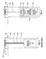
- FIG. 2 illustrates an exemplary downhole tool string 210 attached to a non-electric cable (slickline) 220, which is lowered down a well bore 230.
- the tool string 210 comprises a triggering device 212, a battery 214, a power control interface 216 and an electric downhole tool 218.
- the power control interface 216 provides autonomous control of the tool 218, which may be any suitable downhole tool, such as those typically operated on electric cables (wireline).
- the tool 218 may perform bailing operations, set a mechanical plug or packer, or set an inflatable plug or packer. Power control operations traditionally performed via wireline by an operator on a surface 250 are performed by the power control interface 218.
- the term autonomous means without intervention from the surface. In other words, once the tool is activated ( i.e. , triggered, the tool operates without surface intervention).
- the triggering device 212 generates a trigger signal upon the occurrence of predetermined triggering conditions.
- the triggering device 212 may monitor parameters such as bore hole temperature (BHT), bore hole pressure (BHP), and movement of the tool string 210.
- the triggering device 212 may generate a trigger signal upon determining the tool string 210 has stopped moving (i.e. has reached a desired depth) and that the BHT and BHP are within the operating limits of the tool 218.
- a trigger signal may be generated by lowering a slip ring device (not shown) down the slickline 220 to contact a switch (not shown) on a top surface of the triggering device 212.
- the trigger signal may be any suitable type signal, and for some embodiments, the triggering device 212 may supply a voltage signal from the battery 214 to the power control interface 216 as a trigger signal.
- the battery 214 may be any suitable battery capable of providing sufficient power to operate the tool 218. A physical size of the battery 214 depends on the operating power of the tool. For example, a battery capable of supplying 120 volts at 1.5 amps to a tool for .5 hours may be over six feet long if a diameter of the well bore is 2.5 inches.
- the power control interface 216 In response to receiving the trigger signal, the power control interface 216 converts a voltage signal from the battery 214 into an output voltage signal suitable for operating the tool 218.
- the power control interface 216 applies the output voltage signal to the tool 218.
- the power control interface 216 autonomously controls the tool 218 by varying the output voltage signal applied to the tool 218 according to a predetermined power control sequence. Hence, the combination of the battery 214 and the power control interface 216 acts as an intelligent power supply.
- the tool assembly may be lowered down the wellbore on a lowering member other than a slickline, such as a coiled tubing.
- a slickline such as a coiled tubing.
- the methods and apparatus described herein for operating an electric tool on slickline may also be applied to operating an electric tool deployed on coiled tubing. In other words, there is typically no power supplied to a tool assembly deployed on a coiled tubing.
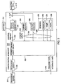
- FIG. 3 illustrates a block diagram of an embodiment of the power control interface 216.
- the power control interface 216 comprises a regulator circuit 310, a power control logic circuit 320, an output voltage converter 330, a current monitor 350, a voltage monitor 360, and sensors 370.
- the regulator circuit 310 regulates the trigger signal (which may be the battery voltage signal) to a suitable voltage level to operate the power control logic circuit 320.
- the output voltage converter 330 converts the battery voltage signal to an output voltage signal V OUT as a function of control signals 342 generated by the power control logic circuit 320.
- the control signals 342 determine a level of V OUT and whether V OUT is applied to the toot.
- Exemplary output voltages include, but are not limited to 24V, 120V, and 180V, and may be AC or DC.
- the output voltage converter 330 may comprise any suitable circuitry such as digital to analog converters (DACs), mechanical relays, solid state relays, and/or field effect transistors (FETs). Further, the output voltage converter 330 may generate different output voltages V OUT to power and control different tools autonomousty.
- DACs digital to analog converters
- FETs field effect transistors
- the current monitor 350 and voltage monitor 360 monitor a current draw of the tool and a voltage applied to the tool, respectively, and provide analog inputs 344 to the power control logic circuit 320.
- Sensors 370 may comprise any combination of suitable sensors, such as a pressure sensor 372, a temperature sensor 374 and an accelerometer 376.
- the power control logic circuit 320 may determine a triggering event has occurred based on analog inputs 344 provided by the sensors 370, eliminating a need for the external triggering device 212.
- the power control logic 320 may determine if one or more parameters in the wellbore are within a predetermined range prior to operating the tool 218.
- the tool 218 may be an inflation tool and the power control logic 320 may confirm that downhole temperature is compatible with materials of an inflatable element prior to operating the tool to set the Inflatable element.
- the power control logic 320 may also include circuitry for wireless communication of data from the sensors 370 to a surface. Monitoring downhole parameters prior to operating a tool and communicating sensor data to a surface is described in US 6,886,631 filed on August 5, 2002 , entitled “Inflation Tool with Real-Time Temperature and Pressure Probes"
- the power control logic circuit 320 may be any suitable circuitry to autonomously control the tool by varying the output voltage V OUT applied to the tool 218 according to a predetermined power control sequence.
- the power control logic circuit 320 may comprise a microprocessor 322 in communication with a memory 324.
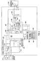
- Figure 4 is an exemplary schematic view of the power control interface 218.
- Figure 5 is a flow diagram illustrating exemplary operations of a method 500 according to an embodiment of the present Invention.
- Figure 5 may be described with reference to the exemplary embodiment of Figure 4 .
- the exemplary operations of Figure 5 may be performed by embodiments other than that illustrated in Figure 4 .
- the exemplary embodiment of Figure 4 is capable of performing operations other than those illustrated in Figure 5 .
- the listed components may be extended temperature components, suitable for downhole use (downhole temperatures may reach or exceed, 149°C (300° F))
- the method 500 begins at step 510, by receiving a trigger signal from a triggering device.
- the trigger signal is regulated by the regulator circuit 310 to a supply voltage V CC suitable to power the power control logic circuit 320.
- the regulator circuit 310 may comprise a single regulator chip 312, or any other suitable circuitry.
- a reset circuit 314 holds the power control logic circuit 320 in a reset condition for a short period of time to ensure the trigger signal is valid and that the supply voltage Vcc is stable.
- the power control logic circuit 320 may be powered from the trigger signal. Alternatively, the power control logic circuit 320 may be powered from an internal battery (not shown) or the external battery 214. A current draw of the power control logic circuit 320 may be insignificant when compared to a current draw of an attached tool 218.
- the triggering device 212 supplies a battery voltage signal from the battery 214 as a trigger signal.
- the power control logic circuit 320 comprises a microprocessor 322 and a memory 324.
- the microprocessor 322 may be any suitable type microprocessor configured to perform the power control sequence 326.
- the microprocessor may also be an extended temperature microprocessor suitable for downhole operations. Examples of extended temperature microprocessors include the 30100600 and 30100700 model microprocessors, available from Elcon Technology of Phoenix, AZ, which are rated for operation up to 175°C (347°F).
- the memory 324 may be internal or external to the microprocessor and may be any suitable type memory.
- the memory 324 may be a battery-backed volatile memory or a non-volatile memory, such as a one-time programmable memory (OT-PROM) or a flash memory.
- OTPROM one-time programmable memory
- the memory may be any combination of suitable external or internal memories.
- the memory 324 may store a power control sequence 326 and a data log 328.
- the data log 328 may store data read from the current monitor 350, voltage monitor 360, and sensors 370.
- the power control interface 216 may be retrieved from the well bore and the data log 328 may be uploaded from the memory 324 via the program/data interface lines 346 using any suitable communications protocol, such as a serial communications protocol.
- the data log 328 may provide an operator with valuable information regarding operating conditions.
- the power control sequence 326 may be stored in any data format suitable for execution by the microprocessor 322.
- the power control sequence 326 may be stored as executable program instructions.
- the power control sequence may be stored as parameters in a data file that specify voltage levels and cycle times or other parameters, such as temperature and/or pressure thresholds.
- the power control interface 216 is configured to perform different power control sequences, thus allowing autonomously control of different tools.
- different power control sequences may define output voltages of differing levels so a power control interface 216 may control tools with different operating voltages.
- the power control sequence 326 may be generated on a computer using any suitable programming tool or editor.
- the power control sequence may be generated by compiling a ladder logic program created using a ladder logic editor.
- the ladder logic program may define various voltage levels, switching times and switching events, for example, based on inputs from the current monitor 350, voltage monitor 360, and sensors 370.
- a power control sequence may be selected from a number of predefined power control sequences, for example, correspond to operating sequences for different tools. Accordingly, for some embodiments, a power control sequence may be chosen by selecting the corresponding tool.
- the power control sequence 326 may be downloaded to the memory 324 via the program/data interface lines 346 using any suitable communications protocol, such as a serial communications protocol.
- a set of predefined power control sequences is stored in the memory 324 and the power control interface 216 is configured by selecting one of the predefined power control sequences, for example, by downloading a selection parameter or by setting a selection switch on a PCB of the power control interface 216.
- the microprocessor 322 may read the downloaded selection parameter or the selection switch to determine which predetermined power control sequence to execute.
- an output voltage signal is generated from a battery voltage signal.
- the output voltage signal is applied to the tool in response to receiving a trigger signal.
- the output voltage signal V OUT may be substantially equal to the battery voltage signal, or the output voltage converter 330 may transform (i.e. step up or step down) the battery voltage signal to generate a different output voltage signal.
- a voltage level of V OUT is determined by the tool 218, and a particular time in the power control sequence 326.
- V OUT may be generated from the battery voltage signal prior to receiving the trigger signal. However, V OUT is not applied to the tool 218 prior to receiving the trigger signal.
- the output voltage signal applied to the tool is varied to autonomously control the tool.
- the output voltage signal V OUT is varied according to the power control sequence 326 performed by the microprocessor.
- the output voltage converter 330 may comprise any suitable circuitry to vary V OUT in response to control signals 342 generated by the microprocessor 322, as required by the power control sequence.
- the output voltage converter 330 may comprise a combination of relays 332 and 334 to apply V OUT to the tool 218.
- the relay 332 serves as a switch to apply V OUT to, or remove V OUT from, the tool 218.
- the relay 334 comprises a double pole relay suitable for reversing a polarity of V OUT , by reversing a polarity of traces connected to different sets of inputs. In a first state, the relay 334 applies a positive V OUT to the tool 218, and in a second state the relay 334 applies a negative V OUT to the tool 218.
- the output voltage converter 330 may comprise other circuitry, such as digital to analog converters (DACs) to generate voltage steps of various levels in response to the control signals 342.
- DACs digital to analog converters
- an output filter circuit 336 may be disposed between the output voltage converter 330 and the tool 218.
- the output filter circuit 336 may comprise any suitable circuitry to filter V OUT applied to the tool 218, and may also function as a surge arrestor to prevent a large in-rush of current from the tool upon initial application and/or disconnections of V OUT to the tool 218.
- the microprocessor 322 may be configured to perform a soft start of the tool 218 by slowly raising V OUT to a final value (for example, by pulsing the filter circuit 336) in an effort to minimize a stress and extend a life of the tool 218.
- the microprocessor 322 may vary V OUT as a function of one or more parameters monitored by sensors 370. For example, the microprocessor may discontinue operation if an operating temperature of the tool is exceeded. As another example, the microprocessor 322 may monitor a current draw of the tool as indicated by an analog input 345 generated by the current monitor 350. The microprocessor 322 may disconnect V OUT in response to determining the current draw to the tool has reached a predefined threshold limit, which may indicate a known event, such as a problem with the tool 218 or completion of a tool operation.
- the microprocessor 322 may execute a power control sequence to autonomously control a plurality of tools.
- the output voltage converter may include circuitry to generate more than one voltage, suitable for simultaneously operating more than one tool.
- the microprocessor 322 may operate a different power control sequence for tool, varying an output voltage supplied to each tool.
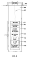
- FIG. 6 illustrate an exemplary tool string 610 attached to a non-electric cable (slickline or coiled tubing) 620, which is lowered down a well bore 630, the tool strong, comprising a triggering device 612, a battery 614, a power control interface 616 and an inflatable tool 618.
- the inflatable tool 618 may comprise a high volume-low pressure pump 622 and a low volume-high pressure pump 624 for inflating an inflatable mapiber 6213.
- power contol operations traditionally performed pro wireline by an operator on a surface 650 are perfomed by the power control interface.
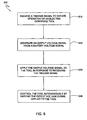
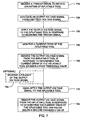
- Figure 7 is a flow diagram illustrating exemplary operations of a method 700 for operating an inflatable tool according to an embodiment of the present invention.
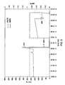
- the exemplary operations of Figure 7 may be illustrated with reference to Figure 6 and Figure 8 , which illustrates an exemplary graph of current and voltage supplied to an inflatable tool as a function of time.
- the voltages, currents and time are for illustrative purposes only, and may vary according to a particular inflatable tool.
- Steps 710 through 730 mirror the operations of steps 510 through 530 of Figure 5 .
- the method 700 begins at step 710, by receiving a trigger signal from a triggering device.
- a trigger signal is generated from a battery voltage signal.
- the output voltage signal is applied to the inflatable tool in response to receiving the trigger signal.
- the inflatable tool may begin inflating the inflatable member 626 with the high volume-low pressure pump 622.
- a current draw of the inflatable tool is monitored.
- the output voltage supplied to the inflatable tool is removed in response to determining the current draw of the inflatable tool is greater than a first threshold value.
- the current draw of the inflatable tool 618 may be proportional to a pressure of an inflatable member 626.
- a sharp rise 810 in the current draw of the inflatable tool may indicate the high volume-low pressure pump 622 has inflated the inflatable member 626 to a predetermined pressure.
- the output voltage signal disconnected from the inflatable tool corresponds to the zero voltage in Figure 8 for the cycle time T OFF .
- the output voltage signal is again applied to the inflatable tool 618.
- the inflatable tool may begin inflating the inflatable member 626, this time with the low volume-high pressure pump 624, which may be able to inflate the inflatable member 626 to a higher pressure than the high volume-low pressure pump 622.
- a second pump (or pumping operation) may be operated by applying a voltage signal of opposite polarity to the inflatable tool. Therefore, for optional step 760, a polarity of the output voltage signal is reversed prior to again applying the output voltage signal to the inflatable tool.
- the output voltage signal is removed from the inflatable tool 618 in response to determining the current draw of the inflatable tool has fallen below a second threshold value.
- the inflatable tool 618 may be designed to automatically release from the inflatable member 626 when the inflatable member 626 is inflated to a predetermined pressure. This automatic release may be indicated by a sharp decrease 820 in the current draw of the inflatable tool 618.
- FIGS 9A and 9B illustrate a side view and a top view, respectively, of an exemplary tool string 910 attached to a slickline 920.
- the tool string 910 comprises a trigger device 912, a battery 914, a power control interface 916 and a perforating tool 918 for perforating a pipe 932.
- the perforating tool 918 may be anchored to a fixed location in the pipe 932 prior to the operations described below.
- the perforating tool 918 may be anchored by an inflatable packing device (not shown), according to the previously described method.
- One challenge in operating the perforating tool 918 is to perforate the pipe 932 without causing damage to an adjacent pipe 942.
- the perforating tool 918 may comprise a ferrous sensor 924 to detect a location of the adjacent pipe 942.
- the ferrous sensor 924 may be located to generate a signal when a perforating device 922 is pointing in an opposite direction of the adjacent pipe 942.
- the tool 924 is commonly referred to as an electromagnetic orienting (EMO) tool.
- the power control interface may generate a signal to rotate the perforating tool 918 while monitoring the signal generated by the ferrous signal to determine a direction of the perforating device 922 with respect to the adjacent pipe 942.
- the power control signal 916 may then generate a signal to fire the perforating device 922 in response to determining the perforating device 922 is pointing away from the adjacent pipe 942.
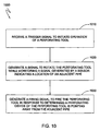
- FIG. 10 is a flow diagram illustrating exemplary operations of a method 1000 for operating a perforating tool according to an embodiment of the present invention.
- the power control interface 916 receives a trigger signal from the triggering device 912.
- the power control interface 916 generates a signal to rotate the perforating tool 918 while monitoring the signal generated by the ferrous sensor 924.
- the power control interface 916 may then generate a firing signal to fire the perforating device 922 in response to determining the perforating device 922 is pointing away from the adjacent pipe 942.
- the power control interface 916 may rotate the perforating device 922 at least one additional rotation while monitoring the signal generated by the ferrous sensor 924.
- the power control interface 916 may compare a location indicated by the signal generated on the additional rotation to a location indicated by the prior signal to ensure both signals indicate a consistent location. If both signals indicate a consistent location, the power control interface 916 may generate the firing signal to fire the perforating device 922. However, if the signals indicate inconsistent results, additional rotations may be monitored or the operations may be terminated to avoid possibly damaging the adjacent pipe 942.
- the ferrous sensor 924 and perforating device 922 may rotate independently of each other. Accordingly, the method described above may be modified such that the power control interface 916 may rotate the ferrous sensor 924 to determine a location of the adjacent pipe 942 and subsequently rotate the perforating device 922. Further, the method described above may also be modified to fire a perforating device away from more than one adjacent pipe.
- Embodiments of the present invention provide a method, system and apparatus for autonomous control of downhole tools on inexpensive slickline, which may reduce operating costs.
- a power control interface performs power control operations traditionally performed via wireline by an operator on the surface. Accordingly, operating costs may be further reduced by limiting a number of skilled operators required to operate the tool.
Abstract
Claims (7)
- Procédé d'exploitation d'un outil électrique de fond de puits (218) comprenant les étapes consistant à :attacher l'outil à une interface de commande d'alimentation ;abaisser l'outil et l'interface de commande d'alimentation dans un puits de forage (230) sur un câble non électrique (220) ;recevoir un signal déclencheur de l'interface de commande d'alimentation (216) ; eten réponse à la réception du signal déclencheur, commander de façon autonome l'outil avec l'interface de commande d'alimentation en faisant varier une tension de sortie fournie à l'outil en conformité avec une séquence de commande d'alimentation (326) stockée dans une mémoire (324) de l'interface de commande d'alimentation, où la séquence de commande d'alimentation est choisie parmi une liste de séquences de commande d'alimentation prédéterminées stockées dans ladite mémoire.
- Procédé selon la revendication 1, comprenant en outre l'étape consistant à télécharger la séquence de commande d'alimentation dans la mémoire de l'interface de commande d'alimentation.
- Procédé selon la revendication 1, comprenant en outre l'étape consistant à télécharger un paramètre de sélection dans la mémoire de l'interface de commande d'alimentation, où le paramètre de sélection détermine quelle séquence de commande d'alimentation prédéterminée est choisie dans la liste.
- Procédé selon la revendication 1, comprenant en outre l'étape consistant à surveiller un ou plusieurs capteurs par l'interface de commande d'alimentation.
- Procédé selon la revendication 4, dans lequel la variation d'une tension de sortie fournie à l'outil en conformité avec la séquence de commande d'alimentation comprend la variation de la tension de sortie en fonction de données réunies depuis les un ou plusieurs capteurs.
- Procédé selon la revendication 4, comprenant en outre les étapes consistant à : consigner des données réunies des un ou plusieurs capteurs en mémoire ; et récupérer dans la mémoire les données des capteurs qui y sont consignées.
- Système comprenant :un outil électrique de fond de puits (218) ;une interface de commande d'alimentation (216) couplée à l'outil électrique de fond de puits ; etun dispositif déclencheur (212) configuré pour fournir un signal déclencheur à l'interface de commande d'alimentation et en réponse à la réception du signal déclencheur, l'outil étant commandé de façon autonome avec l'interface de commande d'alimentation en faisant varier une tension de sortie fournie à l'outil en conformité avec une séquence de commande d'alimentation (326) stockée dans une mémoire (324) de l'interface de commande d'alimentation, où la séquence de commande d'alimentation est choisie dans une liste de séquences de commande d'alimentation prédéterminées stockées dans cette mémoire.
Applications Claiming Priority (3)
| Application Number | Priority Date | Filing Date | Title |
|---|---|---|---|
| US10/212,673 US6945330B2 (en) | 2002-08-05 | 2002-08-05 | Slickline power control interface |
| US212673 | 2002-08-05 | ||
| PCT/US2003/024471 WO2004013457A2 (fr) | 2002-08-05 | 2003-08-05 | Interface de reglage de puissance par l'intermediaire d'un cable lisse |
Publications (2)
| Publication Number | Publication Date |
|---|---|
| EP1529150A2 EP1529150A2 (fr) | 2005-05-11 |
| EP1529150B1 true EP1529150B1 (fr) | 2011-11-23 |
Family
ID=31187823
Family Applications (1)
| Application Number | Title | Priority Date | Filing Date |
|---|---|---|---|
| EP03767205A Expired - Fee Related EP1529150B1 (fr) | 2002-08-05 | 2003-08-05 | Interface de reglage de puissance par l'intermediaire d'un cable lisse |
Country Status (5)
| Country | Link |
|---|---|
| US (2) | US6945330B2 (fr) |
| EP (1) | EP1529150B1 (fr) |
| CA (2) | CA2463774C (fr) |
| NO (1) | NO335590B1 (fr) |
| WO (1) | WO2004013457A2 (fr) |
Families Citing this family (51)
| Publication number | Priority date | Publication date | Assignee | Title |
|---|---|---|---|---|
| US7389183B2 (en) * | 2001-08-03 | 2008-06-17 | Weatherford/Lamb, Inc. | Method for determining a stuck point for pipe, and free point logging tool |
| US6945330B2 (en) * | 2002-08-05 | 2005-09-20 | Weatherford/Lamb, Inc. | Slickline power control interface |
| US7836946B2 (en) | 2002-10-31 | 2010-11-23 | Weatherford/Lamb, Inc. | Rotating control head radial seal protection and leak detection systems |
| US7051810B2 (en) | 2003-09-15 | 2006-05-30 | Halliburton Energy Services, Inc. | Downhole force generator and method for use of same |
| US7926593B2 (en) | 2004-11-23 | 2011-04-19 | Weatherford/Lamb, Inc. | Rotating control device docking station |
| US8826988B2 (en) | 2004-11-23 | 2014-09-09 | Weatherford/Lamb, Inc. | Latch position indicator system and method |
| US7588080B2 (en) * | 2005-03-23 | 2009-09-15 | Baker Hughes Incorporated | Method for installing well completion equipment while monitoring electrical integrity |
| US7896071B2 (en) * | 2005-05-02 | 2011-03-01 | Shane Hinds | Method for continous downhole fluid release and well evaluation |
| US7383883B2 (en) * | 2005-08-15 | 2008-06-10 | Schlumberger Technology Corporation | Apparatus and method to detect a signal associated with a component |
| US7367397B2 (en) | 2006-01-05 | 2008-05-06 | Halliburton Energy Services, Inc. | Downhole impact generator and method for use of same |
| US7467661B2 (en) | 2006-06-01 | 2008-12-23 | Halliburton Energy Services, Inc. | Downhole perforator assembly and method for use of same |
| US7389821B2 (en) * | 2006-11-14 | 2008-06-24 | Baker Hughes Incorporated | Downhole trigger device having extrudable time delay material |
| EP2122120B1 (fr) * | 2007-02-12 | 2019-06-19 | Weatherford Technology Holdings, LLC | Dispositif et procédés d'essai d'écoulement de zones de formation |
| US8022839B2 (en) * | 2007-07-30 | 2011-09-20 | Schlumberger Technology Corporation | Telemetry subsystem to communicate with plural downhole modules |
| DK178464B1 (da) * | 2007-10-05 | 2016-04-04 | Mærsk Olie Og Gas As | Fremgangsmåde til at forsegle en del af annulus mellem et brøndrør og en brøndboring |
| US7997345B2 (en) | 2007-10-19 | 2011-08-16 | Weatherford/Lamb, Inc. | Universal marine diverter converter |
| US8844652B2 (en) | 2007-10-23 | 2014-09-30 | Weatherford/Lamb, Inc. | Interlocking low profile rotating control device |
| US8286734B2 (en) | 2007-10-23 | 2012-10-16 | Weatherford/Lamb, Inc. | Low profile rotating control device |
| US7878242B2 (en) * | 2008-06-04 | 2011-02-01 | Weatherford/Lamb, Inc. | Interface for deploying wireline tools with non-electric string |
| US7802619B2 (en) * | 2008-09-03 | 2010-09-28 | Probe Technology Services, Inc. | Firing trigger apparatus and method for downhole tools |
| US7987901B2 (en) * | 2008-09-29 | 2011-08-02 | Baker Hughes Incorporated | Electrical control for a downhole system |
| US8240387B2 (en) * | 2008-11-11 | 2012-08-14 | Wild Well Control, Inc. | Casing annulus tester for diagnostics and testing of a wellbore |
| US8322432B2 (en) | 2009-01-15 | 2012-12-04 | Weatherford/Lamb, Inc. | Subsea internal riser rotating control device system and method |
| US9359853B2 (en) | 2009-01-15 | 2016-06-07 | Weatherford Technology Holdings, Llc | Acoustically controlled subsea latching and sealing system and method for an oilfield device |
| US8191623B2 (en) * | 2009-04-14 | 2012-06-05 | Baker Hughes Incorporated | Slickline conveyed shifting tool system |
| US8210251B2 (en) * | 2009-04-14 | 2012-07-03 | Baker Hughes Incorporated | Slickline conveyed tubular cutter system |
| US8136587B2 (en) * | 2009-04-14 | 2012-03-20 | Baker Hughes Incorporated | Slickline conveyed tubular scraper system |
| US8056622B2 (en) * | 2009-04-14 | 2011-11-15 | Baker Hughes Incorporated | Slickline conveyed debris management system |
| US8109331B2 (en) * | 2009-04-14 | 2012-02-07 | Baker Hughes Incorporated | Slickline conveyed debris management system |
| US8151902B2 (en) * | 2009-04-17 | 2012-04-10 | Baker Hughes Incorporated | Slickline conveyed bottom hole assembly with tractor |
| US8347983B2 (en) | 2009-07-31 | 2013-01-08 | Weatherford/Lamb, Inc. | Drilling with a high pressure rotating control device |
| US8636062B2 (en) * | 2009-10-07 | 2014-01-28 | Halliburton Energy Services, Inc. | System and method for downhole communication |
| US8607863B2 (en) * | 2009-10-07 | 2013-12-17 | Halliburton Energy Services, Inc. | System and method for downhole communication |
| US8365825B1 (en) * | 2009-11-06 | 2013-02-05 | Halliburton Energy Services, Inc. | Suppressing voltage transients in perforation operations |
| US8347982B2 (en) | 2010-04-16 | 2013-01-08 | Weatherford/Lamb, Inc. | System and method for managing heave pressure from a floating rig |
| US9175542B2 (en) | 2010-06-28 | 2015-11-03 | Weatherford/Lamb, Inc. | Lubricating seal for use with a tubular |
| US8624530B2 (en) * | 2011-06-14 | 2014-01-07 | Baker Hughes Incorporated | Systems and methods for transmission of electric power to downhole equipment |
| US20130037260A1 (en) * | 2011-08-10 | 2013-02-14 | Stewart D. Reed | Systems and Methods for Downhole Communications Using Power Cycling |
| US9133671B2 (en) | 2011-11-14 | 2015-09-15 | Baker Hughes Incorporated | Wireline supported bi-directional shifting tool with pumpdown feature |
| RU2500881C1 (ru) * | 2012-06-20 | 2013-12-10 | Открытое акционерное общество "Всероссийский научно-исследовательский и проектно-конструкторский институт по использованию энергии взрыва в геофизике" (ОАО "ВНИПИвзрывгеофизика") | Способ инициирования перфораторов, спускаемых на насосно-компрессорных трубах |
| US9267346B2 (en) * | 2012-07-02 | 2016-02-23 | Robertson Intellectual Properties, LLC | Systems and methods for monitoring a wellbore and actuating a downhole device |
| BR112015030004B1 (pt) * | 2013-08-16 | 2021-09-08 | Halliburton Energy Services, Inc | Conjunto de fundo de poço para um poço |
| WO2015178901A1 (fr) * | 2014-05-21 | 2015-11-26 | Halliburton Energy Services, Inc. | Bloc-batterie multi-passage récupérable pour outils de câbles lisses |
| US10337270B2 (en) * | 2015-12-16 | 2019-07-02 | Neo Products, LLC | Select fire system and method of using same |
| WO2019084192A1 (fr) | 2017-10-26 | 2019-05-02 | Non-Explosive Oilfield Products, Llc | Outil de positionnement de fond de trou à actionneur fluidique et son procédé d'utilisation |
| CN214352217U (zh) | 2018-02-28 | 2021-10-08 | 米沃奇电动工具公司 | 电动工具 |
| CN111788053A (zh) | 2018-02-28 | 2020-10-16 | 米沃奇电动工具公司 | 用于电动工具的模拟停滞系统和方法 |
| GB201804719D0 (en) * | 2018-03-23 | 2018-05-09 | Kaseum Holdings Ltd | Apparatus and method |
| CA3144926C (fr) * | 2018-04-11 | 2023-05-23 | Thru Tubing Solutions, Inc. | Systemes de perforation et regulation d'ecoulement destines a etre utilises avec des completions de puits |
| US11248453B2 (en) * | 2020-06-22 | 2022-02-15 | Halliburton Energy Service, Inc. | Smart fracturing plug with fracturing sensors |
| US11466559B2 (en) | 2020-07-31 | 2022-10-11 | Baker Hughes Oilfield Operations Llc | Downhole tool sensor arrangements and associated methods and systems |
Family Cites Families (34)
| Publication number | Priority date | Publication date | Assignee | Title |
|---|---|---|---|---|
| US3294163A (en) * | 1959-02-24 | 1966-12-27 | Schlumberger Well Surv Corp | Orienting and perforating methods and apparatus |
| US3105546A (en) * | 1959-09-14 | 1963-10-01 | Camco Inc | Well perforating control |
| US3104709A (en) * | 1960-03-01 | 1963-09-24 | Jersey Prod Res Co | Well perforating apparatus |
| US3097693A (en) * | 1960-07-21 | 1963-07-16 | Jersey Prod Res Co | Method of perforation of well pipe |
| US3704749A (en) * | 1971-05-06 | 1972-12-05 | Nl Industries Inc | Method and apparatus for tool orientation in a bore hole |
| US3964553A (en) * | 1975-09-04 | 1976-06-22 | Go International, Inc. | Borehole tool orienting apparatus and systems |
| US4410051A (en) * | 1981-02-27 | 1983-10-18 | Dresser Industries, Inc. | System and apparatus for orienting a well casing perforating gun |
| US4849699A (en) * | 1987-06-08 | 1989-07-18 | Mpi, Inc. | Extended range, pulsed induction logging tool and method of use |
| US4901069A (en) * | 1987-07-16 | 1990-02-13 | Schlumberger Technology Corporation | Apparatus for electromagnetically coupling power and data signals between a first unit and a second unit and in particular between well bore apparatus and the surface |
| US4852648A (en) * | 1987-12-04 | 1989-08-01 | Ava International Corporation | Well installation in which electrical current is supplied for a source at the wellhead to an electrically responsive device located a substantial distance below the wellhead |
| US4916617A (en) * | 1988-01-20 | 1990-04-10 | Delaware Capital Formation | Controller for well installations |
| US5343963A (en) | 1990-07-09 | 1994-09-06 | Bouldin Brett W | Method and apparatus for providing controlled force transference to a wellbore tool |
| US5146983A (en) * | 1991-03-15 | 1992-09-15 | Schlumberger Technology Corporation | Hydrostatic setting tool including a selectively operable apparatus initially blocking an orifice disposed between two chambers and opening in response to a signal |
| NO305810B1 (no) * | 1991-06-14 | 1999-07-26 | Baker Hughes Inc | Trekk-utl°seranordning for anvendelse i et br°nnhull, samt fremgangsmÕte for plassering av et fluiddrevet br°nnhull - i et br°nnhull |
| US5234057A (en) | 1991-07-15 | 1993-08-10 | Halliburton Company | Shut-in tools |
| US5236047A (en) * | 1991-10-07 | 1993-08-17 | Camco International Inc. | Electrically operated well completion apparatus and method |
| US5236048A (en) * | 1991-12-10 | 1993-08-17 | Halliburton Company | Apparatus and method for communicating electrical signals in a well, including electrical coupling for electric circuits therein |
| GB9212685D0 (en) * | 1992-06-15 | 1992-07-29 | Flight Refueling Ltd | Data transfer |
| US5492173A (en) | 1993-03-10 | 1996-02-20 | Halliburton Company | Plug or lock for use in oil field tubular members and an operating system therefor |
| GB2290869B (en) * | 1994-06-28 | 1998-07-15 | Western Atlas Int Inc | Slickline conveyed wellbore seismic receiver |
| US5582248A (en) * | 1995-06-02 | 1996-12-10 | Wedge Wireline, Inc. | Reversal-resistant apparatus for tool orientation in a borehole |
| AU751779B2 (en) | 1997-11-26 | 2002-08-29 | Baker Hughes Incorporated | Inflatable packer inflation verification system |
| US6076268A (en) * | 1997-12-08 | 2000-06-20 | Dresser Industries, Inc. | Tool orientation with electronic probes in a magnetic interference environment |
| GB9801010D0 (en) * | 1998-01-16 | 1998-03-18 | Flight Refueling Ltd | Data transmission systems |
| US6105690A (en) * | 1998-05-29 | 2000-08-22 | Aps Technology, Inc. | Method and apparatus for communicating with devices downhole in a well especially adapted for use as a bottom hole mud flow sensor |
| US6586900B2 (en) * | 1999-02-08 | 2003-07-01 | Baker Hughes Incorporated | Method for boosting the output voltage of a variable frequency drive |
| US6367545B1 (en) | 1999-03-05 | 2002-04-09 | Baker Hughes Incorporated | Electronically controlled electric wireline setting tool |
| US6378607B1 (en) * | 1999-06-09 | 2002-04-30 | Schlumberger Technology Corporation | Method and system for oriented perforating in a well with permanent sensors |
| GB0005631D0 (en) * | 2000-03-09 | 2000-05-03 | Expro North Sea Ltd | In-well monitoring and flow control system |
| EP1149980A3 (fr) | 2000-04-25 | 2002-01-30 | Halliburton Energy Services, Inc. | Générateur de pression hydraulique de fond de puits |
| DZ3387A1 (fr) | 2000-07-18 | 2002-01-24 | Exxonmobil Upstream Res Co | Procede pour traiter les intervalles multiples dans un trou de forage |
| US6655460B2 (en) * | 2001-10-12 | 2003-12-02 | Weatherford/Lamb, Inc. | Methods and apparatus to control downhole tools |
| US6820693B2 (en) * | 2001-11-28 | 2004-11-23 | Halliburton Energy Services, Inc. | Electromagnetic telemetry actuated firing system for well perforating gun |
| US6945330B2 (en) * | 2002-08-05 | 2005-09-20 | Weatherford/Lamb, Inc. | Slickline power control interface |
-
2002
- 2002-08-05 US US10/212,673 patent/US6945330B2/en not_active Expired - Lifetime
-
2003
- 2003-08-05 WO PCT/US2003/024471 patent/WO2004013457A2/fr not_active Application Discontinuation
- 2003-08-05 CA CA002463774A patent/CA2463774C/fr not_active Expired - Fee Related
- 2003-08-05 EP EP03767205A patent/EP1529150B1/fr not_active Expired - Fee Related
- 2003-08-05 CA CA2664977A patent/CA2664977C/fr not_active Expired - Fee Related
-
2004
- 2004-09-21 NO NO20043946A patent/NO335590B1/no not_active IP Right Cessation
-
2005
- 2005-08-23 US US11/209,899 patent/US7152680B2/en not_active Expired - Lifetime
Also Published As
| Publication number | Publication date |
|---|---|
| US7152680B2 (en) | 2006-12-26 |
| WO2004013457A3 (fr) | 2004-04-08 |
| CA2463774A1 (fr) | 2004-02-12 |
| US6945330B2 (en) | 2005-09-20 |
| EP1529150A2 (fr) | 2005-05-11 |
| NO20043946L (no) | 2004-09-21 |
| CA2463774C (fr) | 2009-10-13 |
| CA2664977C (fr) | 2012-04-17 |
| WO2004013457A2 (fr) | 2004-02-12 |
| US20040020709A1 (en) | 2004-02-05 |
| NO335590B1 (no) | 2015-01-05 |
| US20050279503A1 (en) | 2005-12-22 |
| CA2664977A1 (fr) | 2004-02-12 |
Similar Documents
| Publication | Publication Date | Title |
|---|---|---|
| EP1529150B1 (fr) | Interface de reglage de puissance par l'intermediaire d'un cable lisse | |
| EP1252440B1 (fr) | Commande de mise en service de dispositifs | |
| EP1252414B1 (fr) | Procede et dispositif de fonctionnement a actionneurs par elements extensibles | |
| US6273187B1 (en) | Method and apparatus for downhole safety valve remediation | |
| US9243490B2 (en) | Electronically set and retrievable isolation devices for wellbores and methods thereof | |
| US10132131B2 (en) | Pulling tool electromechanical actuated release | |
| US10563473B2 (en) | Method and apparatus for retrieving a tubing from a well | |
| EP3117074B1 (fr) | Mécanisme d'activation d'un outil de fond de trou et son procédé | |
| US6199628B1 (en) | Downhole force generator and method | |
| WO2017213885A1 (fr) | Dispositifs de glissement à actionnement électrique | |
| AU2003258066C1 (en) | Electric power control for sickline operations in wellbores | |
| AU2008202824B2 (en) | Electric power control for slickline operations in wellbores | |
| US6926087B1 (en) | Electro-mechanical wireline anchoring system and method | |
| AU2001294779A1 (en) | Electro-mechanical wireline anchoring system | |
| US20200088014A1 (en) | Mechanical pump spacing adjustment system | |
| US10309197B2 (en) | System and method for autonomous downhole power generation | |
| GB2297568A (en) | Hydraulic power source | |
| US11708742B2 (en) | System to control and optimize the injection of CO2 and real time monitoring of CO2 plume leaks | |
| CA2235956A1 (fr) | Methode de prelevement automatique controle d'echantillons de fluide a partir d'un puits |
Legal Events
| Date | Code | Title | Description |
|---|---|---|---|
| PUAI | Public reference made under article 153(3) epc to a published international application that has entered the european phase |
Free format text: ORIGINAL CODE: 0009012 |
|
| 17P | Request for examination filed |
Effective date: 20040423 |
|
| AK | Designated contracting states |
Kind code of ref document: A2 Designated state(s): AT BE BG CH CY CZ DE DK EE ES FI FR GB GR HU IE IT LI LU MC NL PT RO SE SI SK TR |
|
| AX | Request for extension of the european patent |
Extension state: AL LT LV MK |
|
| DAX | Request for extension of the european patent (deleted) | ||
| RBV | Designated contracting states (corrected) |
Designated state(s): DE DK GB NL |
|
| GRAP | Despatch of communication of intention to grant a patent |
Free format text: ORIGINAL CODE: EPIDOSNIGR1 |
|
| GRAS | Grant fee paid |
Free format text: ORIGINAL CODE: EPIDOSNIGR3 |
|
| GRAA | (expected) grant |
Free format text: ORIGINAL CODE: 0009210 |
|
| AK | Designated contracting states |
Kind code of ref document: B1 Designated state(s): DE DK GB NL |
|
| REG | Reference to a national code |
Ref country code: GB Ref legal event code: FG4D |
|
| REG | Reference to a national code |
Ref country code: DE Ref legal event code: R096 Ref document number: 60339220 Country of ref document: DE Effective date: 20120126 |
|
| REG | Reference to a national code |
Ref country code: NL Ref legal event code: T3 |
|
| PG25 | Lapsed in a contracting state [announced via postgrant information from national office to epo] |
Ref country code: DK Free format text: LAPSE BECAUSE OF FAILURE TO SUBMIT A TRANSLATION OF THE DESCRIPTION OR TO PAY THE FEE WITHIN THE PRESCRIBED TIME-LIMIT Effective date: 20111123 |
|
| PLBE | No opposition filed within time limit |
Free format text: ORIGINAL CODE: 0009261 |
|
| STAA | Information on the status of an ep patent application or granted ep patent |
Free format text: STATUS: NO OPPOSITION FILED WITHIN TIME LIMIT |
|
| 26N | No opposition filed |
Effective date: 20120824 |
|
| REG | Reference to a national code |
Ref country code: DE Ref legal event code: R097 Ref document number: 60339220 Country of ref document: DE Effective date: 20120824 |
|
| REG | Reference to a national code |
Ref country code: NL Ref legal event code: SD Effective date: 20150318 |
|
| REG | Reference to a national code |
Ref country code: DE Ref legal event code: R082 Ref document number: 60339220 Country of ref document: DE Representative=s name: MARKS & CLERK (LUXEMBOURG) LLP, LU |
|
| REG | Reference to a national code |
Ref country code: DE Ref legal event code: R081 Ref document number: 60339220 Country of ref document: DE Owner name: WEATHERFORD TECHNOLOGY HOLDINGS, LLC, HOUSTON, US Free format text: FORMER OWNER: WEATHERFORD/LAMB, INC., HOUSTON, TEX., US Effective date: 20111202 Ref country code: DE Ref legal event code: R082 Ref document number: 60339220 Country of ref document: DE Representative=s name: MARKS & CLERK (LUXEMBOURG) LLP, LU Effective date: 20150417 Ref country code: DE Ref legal event code: R081 Ref document number: 60339220 Country of ref document: DE Owner name: WEATHERFORD TECHNOLOGY HOLDINGS, LLC, HOUSTON, US Free format text: FORMER OWNER: WEATHERFORD/LAMB, INC., HOUSTON, TEX., US Effective date: 20150417 |
|
| REG | Reference to a national code |
Ref country code: GB Ref legal event code: 732E Free format text: REGISTERED BETWEEN 20151029 AND 20151104 |
|
| REG | Reference to a national code |
Ref country code: NL Ref legal event code: RC Free format text: DETAILS LICENCE OR PLEDGE: RIGHT OF PLEDGE, ESTABLISHED Name of requester: DEUTSCHE BANK TRUST COMPANY AMERICAS Effective date: 20200723 |
|
| REG | Reference to a national code |
Ref country code: GB Ref legal event code: 732E Free format text: REGISTERED BETWEEN 20200813 AND 20200819 |
|
| PGFP | Annual fee paid to national office [announced via postgrant information from national office to epo] |
Ref country code: NL Payment date: 20200814 Year of fee payment: 18 |
|
| PGFP | Annual fee paid to national office [announced via postgrant information from national office to epo] |
Ref country code: GB Payment date: 20200701 Year of fee payment: 18 Ref country code: DE Payment date: 20200722 Year of fee payment: 18 |
|
| REG | Reference to a national code |
Ref country code: GB Ref legal event code: 732E Free format text: REGISTERED BETWEEN 20201126 AND 20201202 |
|
| REG | Reference to a national code |
Ref country code: GB Ref legal event code: 732E Free format text: REGISTERED BETWEEN 20210225 AND 20210303 |
|
| REG | Reference to a national code |
Ref country code: DE Ref legal event code: R119 Ref document number: 60339220 Country of ref document: DE |
|
| REG | Reference to a national code |
Ref country code: NL Ref legal event code: MM Effective date: 20210901 |
|
| GBPC | Gb: european patent ceased through non-payment of renewal fee |
Effective date: 20210805 |
|
| PG25 | Lapsed in a contracting state [announced via postgrant information from national office to epo] |
Ref country code: NL Free format text: LAPSE BECAUSE OF NON-PAYMENT OF DUE FEES Effective date: 20210901 |
|
| PG25 | Lapsed in a contracting state [announced via postgrant information from national office to epo] |
Ref country code: GB Free format text: LAPSE BECAUSE OF NON-PAYMENT OF DUE FEES Effective date: 20210805 Ref country code: DE Free format text: LAPSE BECAUSE OF NON-PAYMENT OF DUE FEES Effective date: 20220301 |