EP1528815A2 - Filmscanner - Google Patents
Filmscanner Download PDFInfo
- Publication number
- EP1528815A2 EP1528815A2 EP04090390A EP04090390A EP1528815A2 EP 1528815 A2 EP1528815 A2 EP 1528815A2 EP 04090390 A EP04090390 A EP 04090390A EP 04090390 A EP04090390 A EP 04090390A EP 1528815 A2 EP1528815 A2 EP 1528815A2
- Authority
- EP
- European Patent Office
- Prior art keywords
- mirror
- filter
- light
- sensors
- sensor
- Prior art date
- Legal status (The legal status is an assumption and is not a legal conclusion. Google has not performed a legal analysis and makes no representation as to the accuracy of the status listed.)
- Withdrawn
Links
Images

Classifications
-
- H—ELECTRICITY
- H04—ELECTRIC COMMUNICATION TECHNIQUE
- H04N—PICTORIAL COMMUNICATION, e.g. TELEVISION
- H04N9/00—Details of colour television systems
- H04N9/11—Scanning of colour motion picture films, e.g. for telecine
-
- H—ELECTRICITY
- H04—ELECTRIC COMMUNICATION TECHNIQUE
- H04N—PICTORIAL COMMUNICATION, e.g. TELEVISION
- H04N5/00—Details of television systems
- H04N5/222—Studio circuitry; Studio devices; Studio equipment
- H04N5/253—Picture signal generating by scanning motion picture films or slide opaques, e.g. for telecine
Definitions
- the invention relates to a film scanner for digitizing films according to the Preamble of claim 1.
- the Film scanner an R, G and B sensor, which are arranged side by side. at This known device raises the problem that the generated R, G and B channels must be matched by the spatial offset to each other, since the R, G and B images are not detected simultaneously.
- the invention is therefore based on the technical problem of using a film scanner by means of which the R, G and B images can be recorded simultaneously in real time are.
- the film scanner on the side facing away from the light source of the Film at least one light-splitting element, wherein the partial beams on the associated photoelectric sensors are mapped, wherein the partial beams through the light-splitting elements and / or through the photoelectric sensors assigned filters are converted into corresponding spectrally filtered sub-beams be, with the photoelectric sensors are designed as TDI sensors.
- charge-coupled devices with time delay and Integration function are known for example from DE 197 39 249 A1.
- the extension of the integration time can increase the dynamics without increasing the Luminous flux can be increased, whereby the reduction of the luminous flux for the R, G and B channels due to the light-splitting element are compensated can.
- the light-splitting element consists of two Mirror, wherein a first partial beam from the first mirror to a dichroic Filter is directed with a subordinate mirror, wherein in each case in the emission direction of the dichroic filter and mirror for the reflected part of a photoelectric Sensor is arranged, wherein the spectral channel of the mirror associated Sensor is associated with the spectral range of the dichroic filter.
- the dichroic filter designed as a red filter, so gets the total red portion of the supplied from the mirror of the light-splitting element Light beam on the arranged behind the dichroic filter mirror and is mapped to the associated photoelectric sensor for the R channel.
- the All remaining light (without the red portion) is from the dichroic filter on the mapped to another sensor where a desired spectral component is filtered out can, for example, for the G-channel.
- the transmission capacity of the Dichroic filter chosen such that a non-uniform spectral distribution the light source and / or spectral sensitivity differences of the sensors be compensated.
- the sensor associated with the mirror is a filter assigned, which is further preferably designed as a blue filter.
- the the Partially transparent mirror associated sensor is more preferably than panchromatic sensor or assigned as NIR sensor. This can be with simple means the low spectral sensitivity for the blue spectral component be compensated.
- the partially transparent mirror is such designed that this reflects about 10% of the radiation and 90% passes, wherein These 90% are reflected by the mirror on the sensor with the blue filter.
- the film set a collimator optics arranged behind the at least two semi-transparent mirrors and a mirror are arranged so that the light beam in at least three partial beams is decomposed, wherein in the emission direction of the each reflected a partial photoelectric sensor with associated filter is arranged.
- the partial transmission of the mirrors is selected such that a non-uniform spectral distribution of the light source and / or different Efficiencies of the filters and / or spectral sensitivity differences of Sensors are compensated.
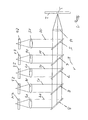
- the film scanner 1 comprises a film stage 2 with a slit-shaped light passage 3. About this film carrier 2, an unillustrated film is moved and from a also broadband light source, not shown radiographs. Behind the Light transmission 3, a collimator optics 4 is arranged. Behind the collimator optics 4 four partially transparent mirrors 5-8 and a mirror 9 are arranged. In the beam path each reflected partial beam 10-14 is an imaging optics 15-19 arranged in the focal plane in each case a photoelectric sensor 20-24 is arranged. The sensors 20-24 are designed as TDI line sensors, which are arranged transversely to the film transport direction.
- the sensor 20 is a Blue filter, the sensor 21, a green filter, the sensor 22, a red filter and the Sensor 23 associated with an NIR filter.
- the partially transmissive mirror 5-8 act as a simple beam splitter or light splitting elements. In general, you can say that the blue fraction of common white light sources is lower than the green or Red component. The same applies to the sensitivity of the sensors. By adjustment the transmissivity of the partially transmissive mirror 5-8 this can now be compensated. For example, 30% of the incident radiation on partially reflecting mirror 5 to the sensor 20 and reflected 70% to the partially transparent Mirror 6 transmitted.
- the partially transmissive mirror can thereby the incident Light beam, for example, be divided so that the partial beam 10 30%, the Partial beam 11 25%, the partial beam 12 20%, the partial beam 13 15%, and the partial beam 14th Has 10% of the incident light beam.
- the sensor 24 generates panchromatic picture.
- the Film scanner 1 a lens 30, a light-splitting element 31 with two mirrors 32, 33, a dichroic filter 34, a mirror 35, a semitransparent mirror 36, a mirror 37 and four TDI sensors 38-41.
- the sensor 38 for the Red channel the sensor 39 for the green channel
- the sensor 40 for the panchromatic channel the sensor 41 for the blue channel.
- the Dichroic filter 34 is designed as a red passage filter.
- a green filter 42 In front of the sensor 39 is a green filter 42 and in front of the sensor 41, a blue filter 43 is arranged.
- the Sensors 38-41 are again transverse to the direction of movement T of the film 44 arranged, wherein the film 44 as in the embodiment of FIG.
- a broadband light source is irradiated, wherein a light passage in the Film stage is shown on the lens 30.
- the slit-shaped light passage is imaged via the lens 30 on the light-splitting element 31 and in two Partial beams 45 and 46 decomposed.
- the decomposition is preferably symmetrical, i.e. the two partial beams each have half the intensity of Input beam on.
- the first partial beam 45 is applied to the dichroic filter 34 directed, wherein the red portion passes the dichroic filter 34, on the mirror 35th falls and is imaged on the sensor 38.
- the remaining part of the partial beam 45 becomes at the dichroic filter 34 and impinges on the green filter 42.
- the green Spectral component passes through the green filter 42 and reaches the sensor 39.
- the red and green channel can also be reversed, and then the passband of the dichroic filter are adjusted accordingly got to.
- the passband of the dichroic filter are adjusted accordingly got to.
- a red filter before the sensor 38 is arranged, for example, to suppress stray light.
- the second partial beam 46 is from the second mirror 33 to the partially transmissive mirror 36 reflected. This reflects some of its radiation, for example 10% the panchromatic sensor 40, whereas 90% are transmitted and on the blue filter 43 are reflected.
- the blue spectral component then passes the Blue filter 43 and passes to the sensor 41.
- the partially transmissive mirror 36 can then again spectral nonuniformities of the light source and spectral differences be compensated for the sensitivity of the sensors 38-41.
Landscapes
- Engineering & Computer Science (AREA)
- Multimedia (AREA)
- Signal Processing (AREA)
- Facsimile Scanning Arrangements (AREA)
- Color Television Image Signal Generators (AREA)
Abstract
Description
- Fig. 1
- eine schematische Darstellung einer ersten Ausführungsform eines Filmscanners und
- Fig. 2
- eine schematische Darstellung einer zweiten Ausführungsform eines Filmscanners.
Claims (8)
- Filmscanner zum Digitalisieren von Filmen, umfassend eine breitbandige Lichtquelle, eine Filmbühne, die mindestens einen Lichtdurchlass aufweist, eine Abbildungsoptik und photoelektrische Sensoren, die mindestens einen R-, G- und B-Kanal bilden,
dadurch gekennzeichnet, dass
der Filmscanner (1) auf der der Lichtquelle abgewandten Seite der Filmbühne (2) mindestens ein lichtspaltendes Element (5-8, 31, 34, 36) aufweist, wobei die Teilstrahlen (10-14) auf die zugeordneten photoelektrischen Sensoren (20-24, 38-41) abgebildet werden, wobei die Teilstrahlen durch die lichtspaltenden Elemente und/oder durch den photoelektrischen Sensoren zugeordnete Filter in entsprechende spektral gefilterte Teilstrahlen umgewandelt werden, wobei die photoelektrischen Sensoren (20-24, 38-41) als TDI-Sensoren ausgebildet sind. - Filmscanner nach Anspruch 1, dadurch gekennzeichnet, dass das lichtspaltende Element (31) aus zwei Spiegel (32, 33) besteht, wobei ein erster Teilstrahl (45) vom ersten Spiegel (32) auf einen dichroitischen Filter (34) mit nachgeordnetem Spiegel (35) gelenkt wird, wobei jeweils in Abstrahlrichtung des dichroitischen Filters (34) und des Spiegels (35) für den reflektierten Teil ein photoelektrischer Sensor (38, 39) angeordnet ist, wobei der Spektralkanal des dem Spiegel (35) zugeordneten Sensors (38) dem Spektralbereich des dichroitischen Filters (34) zugeordnet ist.
- Filmscanner nach Anspruch 2, dadurch gekennzeichnet, dass das Durchlassvermögen des dichroitischen Filters (34) derart gewählt wird, dass eine ungleichförmige spektrale Verteilung der Lichtquelle und/oder spektrale Empfindlichkeitsunterschiede der Sensoren (38-41) kompensiert werden.
- Filmscanner nach einem der vorangegangenen Ansprüche, dadurch gekennzeichnet, dass das lichtspaltende Element (31) aus zwei Spiegel (32, 33) besteht, wobei ein zweiter Teilstrahl (46) vom zweiten Spiegel (33) auf einen teildurchlässigen Spiegel (36) mit nachgeordnetem Spiegel (37) gelenkt wird, wobei jeweils in Abstrahlrichtung des teildurchlässigen Spiegels (36) und des Spiegels (37) für den reflektierten Teil ein photoelektrischer Sensor (40, 41) angeordnet ist, wobei mindestens einem Sensor (41) ein Filter (43) zugeordnet ist.
- Filmscanner nach Anspruch 4, dadurch gekennzeichnet, dass dem dem Spiegel (37) zugeordneten Sensor (41) ein Filter (43) zugeordnet ist.
- Filmscanner nach Anspruch 5, dadurch gekennzeichnet, dass der Filter (43) als Blau-Filter ausgebildet ist.
- Filmscanner nach einem der vorangegangenen Ansprüche, dadurch gekennzeichnet, dass auf der der Lichtquelle abgewandten Seite der Filmbühne eine Kollimator-Optik (4) angeordnet ist, hinter der mindestens zwei teildurchlässige Spiegel (5-8) und ein Spiegel (9) angeordnet sind, so dass der Lichtstrahl in mindestens drei Teilstrahlen (10-14) zerlegt wird, wobei in der Abstrahlrichtung der reflektierten Teilstrahlen (10-14) jeweils ein photoelektrischer Sensor (20-24) angeordnet ist, wobei mindestens drei Sensoren (20-22) ein Filter zugeordnet ist.
- Filmscanner nach Anspruch 7, dadurch gekennzeichnet, dass die Teildurchlässigkeit der Spiegel (5-8) derart gewählt wird, dass eine ungleichförmige spektrale Verteilung der Lichtquelle und/oder unterschiedliche Wirkungsgrade der Filter und/oder spektrale Empfindlichkeitsunterschiede der Sensoren (20-24) kompensiert werden.
Applications Claiming Priority (2)
| Application Number | Priority Date | Filing Date | Title |
|---|---|---|---|
| DE10351705 | 2003-11-03 | ||
| DE2003151705 DE10351705A1 (de) | 2003-11-03 | 2003-11-03 | Filmscanner |
Publications (2)
| Publication Number | Publication Date |
|---|---|
| EP1528815A2 true EP1528815A2 (de) | 2005-05-04 |
| EP1528815A3 EP1528815A3 (de) | 2007-12-19 |
Family
ID=34399681
Family Applications (1)
| Application Number | Title | Priority Date | Filing Date |
|---|---|---|---|
| EP04090390A Withdrawn EP1528815A3 (de) | 2003-11-03 | 2004-10-11 | Filmscanner |
Country Status (2)
| Country | Link |
|---|---|
| EP (1) | EP1528815A3 (de) |
| DE (1) | DE10351705A1 (de) |
Family Cites Families (8)
| Publication number | Priority date | Publication date | Assignee | Title |
|---|---|---|---|---|
| US3585281A (en) * | 1967-12-22 | 1971-06-15 | Printing Dev Inc | Apparatus for optically resolving the light derived from the scanning of a tonal image into color components |
| GB1369864A (en) * | 1970-09-30 | 1974-10-09 | Eastman Kodak Co | Colour signal generating apparatus |
| JPS5133691B2 (de) * | 1971-08-09 | 1976-09-21 | ||
| US4415934A (en) * | 1980-11-19 | 1983-11-15 | Canon Kabushiki Kaisha | Image reading apparatus |
| JPS641365A (en) * | 1987-06-23 | 1989-01-05 | Konica Corp | Color picture reader |
| US5003379A (en) * | 1989-10-16 | 1991-03-26 | Eastman Kodak Company | Telecine scanning apparatus with spectrally-shifted sensitivities responsive to negative or print film dyes |
| IL121689A0 (en) * | 1996-09-06 | 1998-02-22 | Elbit Vision Systems Ltd | Time delay and integration sensor |
| US6532086B1 (en) * | 1999-11-19 | 2003-03-11 | Xerox Corporation | Optical color matrixing using time delay and integration sensor arrays |
-
2003
- 2003-11-03 DE DE2003151705 patent/DE10351705A1/de not_active Ceased
-
2004
- 2004-10-11 EP EP04090390A patent/EP1528815A3/de not_active Withdrawn
Also Published As
| Publication number | Publication date |
|---|---|
| EP1528815A3 (de) | 2007-12-19 |
| DE10351705A1 (de) | 2005-06-16 |
Similar Documents
| Publication | Publication Date | Title |
|---|---|---|
| EP1213568B1 (de) | Vorrichtung zur bildelementweisen Ausmessung eines flächigen Messobjekts | |
| DE2431860C2 (de) | Fokussiereinrichtung für optische Geräte | |
| EP3207356B1 (de) | Vorrichtung und verfahren zur bestimmung der partikelgrösse und/oder der partikelform von partikeln in einem partikelstrom | |
| DE69011314T2 (de) | Fernsehfilmabtasteinrichtung mit spektral verschobenen empfindlichkeiten für negative und dia-film-farbstoffe. | |
| EP3298345B1 (de) | Kamera und verfahren zur dreidimensionalen vermessung und farbvermessung eines dentalen objekts | |
| EP1213569A2 (de) | Vorrichtung zur bildelementweisen Ausmessung eines flächigen Messobjekts | |
| DE102008016167A1 (de) | Farbsensor mit Infrarotkorrektur | |
| DE3686358T2 (de) | Optischer tiefpassfilter fuer eine festkoerper-farbkamera. | |
| DE3434765A1 (de) | Farbteiler, beispielsweise fuer eine fernsehkamera | |
| DE112017004403T5 (de) | Endoskopsystem und charakteristischer betrag-berechnungsverfahren | |
| DE3835976A1 (de) | Digitale bildsignalverarbeitungseinrichtung, insbesondere fuer eine videokamera | |
| DE60204849T2 (de) | Verfahren und einrichtung zur lageerfassung der anschlusskontakte elektronischer bauelemente | |
| DE102019116506A1 (de) | Stereokamerasystem | |
| DE1165303B (de) | Optisches Bilduebertragungssystem | |
| DE10323410A1 (de) | Vorrichtung zur Prüfung von Banknoten | |
| DE69406229T2 (de) | Optische Abbildungsvorrichtung für die Spektralanalyse einer Szene | |
| DE102004059951A1 (de) | Vorrichtung zur Untersuchung von Dokumenten | |
| DE10351705A1 (de) | Filmscanner | |
| EP1185079A2 (de) | Auf- oder Durchlichtscanner und Bildverarbeitungsverfahren für eingescannte Bildvorlagen | |
| EP4654878A1 (de) | Medizinische bildgebungsvorrichtung, endoskopvorrichtung, endoskop und verfahren zur bildgebung | |
| DE102023205077A1 (de) | Verfahren und Vorrichtung zur Bestimmung einer objektabhängigen Fokusablage, Verfahren zur Vermessung eines Objekts und Koordinatenmessgerät | |
| DE102015112769B4 (de) | Vorrichtung und Verfahren zur optischen Probenuntersuchung | |
| DE3211668C2 (de) | Verfahren zur Erhöhung der Auflösung von Fernsehkameras | |
| EP1273878B1 (de) | Verfahren zur Detektion eines Objektes mit unterschiedlichen Auflösungen | |
| DE102004045559B4 (de) | Filmscanner für farbige Bildvorlagen |
Legal Events
| Date | Code | Title | Description |
|---|---|---|---|
| PUAI | Public reference made under article 153(3) epc to a published international application that has entered the european phase |
Free format text: ORIGINAL CODE: 0009012 |
|
| AK | Designated contracting states |
Kind code of ref document: A2 Designated state(s): AT BE BG CH CY CZ DE DK EE ES FI FR GB GR HU IE IT LI LU MC NL PL PT RO SE SI SK TR |
|
| AX | Request for extension of the european patent |
Extension state: AL HR LT LV MK |
|
| RAP1 | Party data changed (applicant data changed or rights of an application transferred) |
Owner name: DEUTSCHES ZENTRUM FUER LUFT- UND RAUMFAHRT E.V. |
|
| PUAL | Search report despatched |
Free format text: ORIGINAL CODE: 0009013 |
|
| AK | Designated contracting states |
Kind code of ref document: A3 Designated state(s): AT BE BG CH CY CZ DE DK EE ES FI FR GB GR HU IE IT LI LU MC NL PL PT RO SE SI SK TR |
|
| AX | Request for extension of the european patent |
Extension state: AL HR LT LV MK |
|
| 17P | Request for examination filed |
Effective date: 20080307 |
|
| 17Q | First examination report despatched |
Effective date: 20080402 |
|
| AKX | Designation fees paid |
Designated state(s): DE FR GB |
|
| STAA | Information on the status of an ep patent application or granted ep patent |
Free format text: STATUS: THE APPLICATION IS DEEMED TO BE WITHDRAWN |
|
| 18D | Application deemed to be withdrawn |
Effective date: 20081014 |