EP1528783A1 - Power supply method and apparatus for wired telecommunication systems - Google Patents
Power supply method and apparatus for wired telecommunication systems Download PDFInfo
- Publication number
- EP1528783A1 EP1528783A1 EP03447287A EP03447287A EP1528783A1 EP 1528783 A1 EP1528783 A1 EP 1528783A1 EP 03447287 A EP03447287 A EP 03447287A EP 03447287 A EP03447287 A EP 03447287A EP 1528783 A1 EP1528783 A1 EP 1528783A1
- Authority
- EP
- European Patent Office
- Prior art keywords
- satellite
- converter
- main
- power supply
- source
- Prior art date
- Legal status (The legal status is an assumption and is not a legal conclusion. Google has not performed a legal analysis and makes no representation as to the accuracy of the status listed.)
- Withdrawn
Links
Images

Classifications
-
- H—ELECTRICITY
- H04—ELECTRIC COMMUNICATION TECHNIQUE
- H04M—TELEPHONIC COMMUNICATION
- H04M19/00—Current supply arrangements for telephone systems
- H04M19/08—Current supply arrangements for telephone systems with current supply sources at the substations
Definitions
- the present invention relates to a device power supply for telecommunication wire system, comprising a main converter, arranged to be connected to a source of main energy and to provide a main voltage to power a satellite unit of the telecommunication system; a source of energy backup power supply, connected to the satellite unit and arranged at provide auxiliary voltage to the satellite unit in case of non-compliance from the main voltage to at least one predetermined criterion.
- the auxiliary power source consists of energy storage elements, for example batteries directly connected to the satellite unit. This generates costs investment in infrastructure and high maintenance costs. In in addition, these local systems are cumbersome.
- An object of the present invention is to mitigate at least one of these disadvantages.
- the device is characterized in that the auxiliary energy source comprises a central module having an input arranged to be connected to a source of energy available at the central office, and an output arranged to be connected to at least one pair of wires (TP), said pair of wires being connected to the satellite unit.
- TP wires
- the remote power system as a source of auxiliary energy, not only is it possible to obtain higher, but also at a lower cost than the systems local power supplies (with batteries) or remote power systems in main source used until today.
- the main source remote supply systems it is possible to reduce the number of pairs, including increasing the current maximum per pair, since losses are generated only by Occasional way when using in rescue mode.
- the invention also relates to a method of power supply for a telecommunication wire system, as well as the use of the remote power system as an auxiliary power source.
- the satellite unit 3 comprises the satellite converters 7, charge 6, and where applicable, the main converter 1. Each satellite converter may, where appropriate, be replaced by several converters in parallel.
- the central module 4 and the source of energy available at the central station 9 constitute the auxiliary energy source 2.
- the current charged by the remote power supply in normal conditions, is almost zero. If the local AC power disappears the remote power supply serves as backup and has a battery life (eg 48V) for several hours.
- the criterion predetermined indicating the non-compliance of the main voltage consists in the non-existence of a tension.
- the conformity of the predetermined criterion is to fall into a voltage range of example +/- 20% around the nominal voltage.
- the converter Principal 1 may integrate this conformity check function with the predetermined criterion.
- the control of compliance with the predetermined criterion would consist of the verification of the temperature of the main converter in a given range.
- Another advantage of the system according to the invention is that it simplifies the main converter and reduces its power nominal.
- the main converter 1 compared to a local food system Classically including batteries as an auxiliary power source, the main converter 1 must be oversized to ensure the possible recharging of the batteries while feeding the load.
- the main converter in conventional systems must in this case integrate battery management functions, such as the control of autonomy, temperature compensation, equalization ("boost mode ”) battery sub-elements, ...
- batteries at the local level are not necessary because the auxiliary power supply is provided by the remote power supply.
- the main converter 1 according to the invention should therefore not be equipped with these battery management functions.
- redundancy of N + x type where N is the number of power base units necessary to feed the load and x being backup units in case of default of one of the N base units.
- a remote power supply redundancy 3 + 1 includes three power supply units as well as a backup unit.
- An advantageous way to implement the system is to design the main converter in the same form and dimensions than a satellite converter. This allows easily transform a known system of conventional tele-power in the system according to the invention by replacing the satellite converter redundant by the main converter.
- the converter principal 1 is part of the satellite unit 3.
- the redundant power supply (3 + 1) it is also advantageous to provide the power of the main power equal to three times the power of a satellite converter.
- Another consequence of using remote power as an auxiliary source is to enable the implementation of parallel of the outputs of the central converters by limiting the disadvantages due to the increase in the maximum current of the series of central converters.
- An example of the inconvenience of Parallel Central Converters in Remote Power Systems used as the main source is dissipation excessive energy due to the larger current in the wire pair.
- the remote power supply is used only in emergency mode, in other words exceptionally. The dissipation of energy is therefore exceptional. This explains in part the efficiency gain of the system according to the invention.
- the lifespan of the whole chain is increased (by a factor four to five) because in normal feeding mode the load is powered by the main converter without going through the remote power supply relief, and in particular without going through the satellite converters. The maintenance costs are therefore greatly reduced.
- the main converter 1 preferably comprises means of testing the emergency power supply. For this purpose, the output voltage of the main converter to a lower value to that of the output voltage under load (for example 48 V) satellite converters for a short period of time (from a few seconds) and simultaneously the main converter checks that its output current is almost zero, in order to check the correct operation of the remote power supply.
- This test could be programmed automatically with a fixed cycle of, for example, one (1) week for a duration of one (1) minute.
- a second form would be to use diet differently, that is to say power the satellite converters 7 at the input, on the twisted pair side, with a higher voltage (for example +/- 180V) to that coming from the central converters (+/- 160V), through an additional diode bridge.
- a very form simple of the main converter 1 would be to use a transformer of 50/60 Hz voltage having a peak-to-peak secondary voltage of 360 V AC. In practice this embodiment would only work with very stable electrical networks.
- a variant of this last montage would be that the local power supply would have as many isolated +/- 180V outputs as tele-power supplies (RPB), so that all RPBs remain well independent.
- RPB tele-power supplies
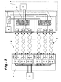
- Figure 3 shows a shape according to Figure 1 improved at the performance level by adding a local auxiliary power supply supplying the auxiliary circuits of the RPBs, the main source of resting consumption. It has the advantage of not having to be in compliance with the constraints of the RFT circuits in the event of a bridge failure diode, but should have (galvanic) isolation between the output of the main converter and the input of the satellite converter. This supply voltage is low (SELV) compared to the shape according to the figure 2.
- the remote power system can be if necessary that described in European Patent Application No. 03391001.9, the content is incorporated by reference, as well as that described in the European Patent Application No. 02077059.0.
Abstract
Description
La présente invention se rapporte à un dispositif d'alimentation d'énergie pour système de télécommunication par fils, comprenant un convertisseur principal, agencé à être relié à une source d'énergie principale et à fournir une tension principale pour alimenter une unité satellite du système de télécommunication; une source d'énergie auxiliaire (alimentation de secours), reliée à l'unité satellite et agencée à fournir une tension auxiliaire à l'unité satellite en cas de non conformité de la tension principale à au moins un critère prédéterminé.The present invention relates to a device power supply for telecommunication wire system, comprising a main converter, arranged to be connected to a source of main energy and to provide a main voltage to power a satellite unit of the telecommunication system; a source of energy backup power supply, connected to the satellite unit and arranged at provide auxiliary voltage to the satellite unit in case of non-compliance from the main voltage to at least one predetermined criterion.
Dans des systèmes connus, la source d'énergie auxiliaire est constituée d'éléments de stockage d'énergie, par exemples des batteries directement reliées à l'unité satellite. Ceci engendre des coûts d'investissement en infrastructure et coûts de maintenance élevés. En outre, ces systèmes locaux sont encombrants.In known systems, the auxiliary power source consists of energy storage elements, for example batteries directly connected to the satellite unit. This generates costs investment in infrastructure and high maintenance costs. In in addition, these local systems are cumbersome.
Un objet de la présente invention est de pallier à au moins un de ces inconvénients.An object of the present invention is to mitigate at least one of these disadvantages.
Suivant l'invention, le dispositif est caractérisé en ce que la source d'énergie auxiliaire comporte un module central ayant une entrée agencée à être reliée à une source d'énergie disponible au central, et une sortie agencée à être reliée à au moins une paire de fils (TP), ladite paire de fils étant relié à l'unité satellite.According to the invention, the device is characterized in that the auxiliary energy source comprises a central module having an input arranged to be connected to a source of energy available at the central office, and an output arranged to be connected to at least one pair of wires (TP), said pair of wires being connected to the satellite unit.
Jusqu'à ce jour, des systèmes de télé-alimentation, comprenant le module central sont connus. De tels systèmes sont utilisés comme source d'énergie principale et présentent comme inconvénient majeur que le rendement global est bas et donc que les pertes d'énergie associées à son utilisation sont importantes. Par exemple, l'efficacité totale de tous les éléments mis en série peuvent être répartis sur la chaíne de conversion d'énergie de la manière suivante : 8 -15 % pour obtenir l'énergie 48V en amont du CPM (convertisseur central); 10 - 15 % dans le convertisseur central; 2 - 30 % dans la paire téléphonique (selon la longueur); 10 - 15 % dans le convertisseur final, soit une perte totale de 27 à 57 %.To this day, remote power systems, including the central module are known. Such systems are used as the main source of energy and present as major disadvantage that the overall yield is low and therefore the Energy losses associated with its use are significant. By For example, the total efficiency of all the elements put in series can be distributed on the energy conversion chain as follows: 8 -15% to obtain the 48V energy upstream of the CPM (converter central); 10 - 15% in the central converter; 2 - 30% in the pair telephone (depending on the length); 10 - 15% in the final converter, a total loss of 27 to 57%.
Ceci implique :
En utilisant le système de télé-alimentation comme source d'énergie auxiliaire, on permet non seulement d'obtenir un rendement plus élevé, mais également à coût moins élevé que les systèmes d'alimentation locales (avec batteries) ou que les systèmes de télé-alimentation en source principales utilisés jusqu'à ce jour. En outre, par rapport aux systèmes de télé-alimentation en source principales, on peut réduire le nombre de paires, notamment en augmentant le courant maximum par paire, vu que les pertes ne sont engendrées que de manière occasionnelle lors de l'utilisation en mode secours. On peut également réduire le coût et simplifier la construction de la source d'énergie auxiliaire vu que le mode principal d'utilisation est le mode d'attente.Using the remote power system as a source of auxiliary energy, not only is it possible to obtain higher, but also at a lower cost than the systems local power supplies (with batteries) or remote power systems in main source used until today. In addition, compared to the main source remote supply systems, it is possible to reduce the number of pairs, including increasing the current maximum per pair, since losses are generated only by Occasional way when using in rescue mode. We can also reduce the cost and simplify the construction of the source of auxiliary power since the main mode of use is the Wait.
D'autres formes de réalisation du dispositif suivant l'invention sont décrites dans les revendications dépendantes. L'invention concerne également un procédé d'alimentation d'énergie pour système de télécommunication par fils,ainsi que l'utilisation du système de télé-alimentation en tant que source d'énergie auxiliaire. Other embodiments of the following device the invention are described in the dependent claims. The invention also relates to a method of power supply for a telecommunication wire system, as well as the use of the remote power system as an auxiliary power source.
Des détails concernant l'invention sont décrits ci-après
faisant référence aux dessins.
L'unité satellite 3 comprend les convertisseurs satellites 7,
la charge 6, et le cas échéant, le convertisseur principal 1. Chaque
convertisseur satellite peut, le cas échéant, être remplacé par plusieurs
convertisseurs mis en parallèle.The
Suivant l'invention, le module central 4 et la source
d'énergie disponible au central 9 constituent la source d'énergie auxiliaire
2.According to the invention, the
Dans la forme de réalisation suivant la figure 1, qui
représente la forme la plus directe, il est important que latension en
charge du convertisseur principale soit plus élevée que la tension à vide
(par exemple 53 V) à la sortie des convertisseurs satellites 7, de sorte
que l'énergie soit fournie à la charge 6 par le convertisseur principal 1
lors du fonctionnement normal. Il est à noter que ce principe de
différence de tension est connu tel quel dans un système classique
d'alimentation locale où la source d'énergie principale est une source AC
et la source d'énergie auxiliaire est constituée d'une série de batteries.In the embodiment according to Figure 1, which
represents the most direct form, it is important that latension in
main converter load is higher than the no-load voltage
(eg 53 V) at the output of the
Ainsi, le courant débité par la télé-alimentation, en
conditions normales, est quasi nul. Si l'alimentation AC locale disparaít
la télé-alimentation sert de secours et dispose d'une autonomie batterie
(par exemple 48V) durant plusieurs heures. Dans ce cas, le critère
prédéterminé indiquant la non conformité de la tension principale
consiste en la non existence d'une tension. En général, la conformité du
critère prédéterminé est de tomber dans une plage de tension de par
exemple +/- 20% autour de la tension nominale. Le convertisseur
principal 1 peut intégrer cette fonction de contrôle de conformité au
critère prédéterminé. Suivant une forme alternative, le contrôle de
conformité au critère prédéterminé consisterait en la vérification de la
température du convertisseur principal dans une plage donnée.Thus, the current charged by the remote power supply, in
normal conditions, is almost zero. If the local AC power disappears
the remote power supply serves as backup and has a battery life
(eg 48V) for several hours. In this case, the criterion
predetermined indicating the non-compliance of the main voltage
consists in the non-existence of a tension. In general, the conformity of the
predetermined criterion is to fall into a voltage range of
example +/- 20% around the nominal voltage. The
De cette façon, on obtient pour l'alimentation un rendement de l'ordre de 90 % et plus, diminué de l'énergie minimum nécessaire pour la télé-alimentation en mode d'attente. L'alimentation locale et les convertisseurs satellite (RPB) peuvent être conçus de sorte qu'ils minimisent l'énergie consommée en mode d'attente. Le gain de rendement sera de l'ordre de 40% pour l'utilisation normale mais évidemment pas en mode secours.In this way, we obtain for the feeding a yield on the order of 90% or more, minus the minimum energy required for remote power in standby mode. Local food and satellite converters (RPBs) can be designed so that they minimize the energy consumed in standby mode. The gain of yield will be of the order of 40% for normal use but obviously not in rescue mode.
Un autre avantage du système suivant l'invention est qu'il
permet de simplifier le convertisseur principal et de réduire sa puissance
nominale. En particulier, par rapport à un système d'alimentation locale
classique comprenant des batteries comme source d'énergie auxiliaires,
le convertisseur principal 1 doit être surdimensionné pour assurer la
recharge éventuelle des batteries tout en alimentant la charge. Le
convertisseur principal dans des systèmes classiques doit dans ce cas
intégrer des fonctions de gestion des batteries, telle que le contrôle de
l'autonomie, la compensation en température, l'égalisation ("boost
mode") des sous-éléments de batteries, ... Dans le système suivant
l'invention, les batteries au niveau local ne sont pas nécessaires, car
l'alimentation auxiliaire est assuré par la télé-alimentation. Le
convertisseur principal 1 suivant l'invention ne doit par conséquent pas
être pourvu de ces fonctions de gestion des batteries.Another advantage of the system according to the invention is that it
simplifies the main converter and reduces its power
nominal. In particular, compared to a local food system
Classically including batteries as an auxiliary power source,
the
Dans des systèmes d'alimentation en télécommunication
connus (locale ou de télé-alimentation), on prévoit une redondance de
type N + x, N étant le nombre d'unités de base d'alimentation
nécessaires pour alimenter la charge et x étant des unité de secours en
cas de défaut d'une des N unités de base. Par exemple, une télé-alimentation
de redondance 3 + 1 comprend trois unités d'alimentation
de base ainsi qu'une unité de secours.In telecommunication power systems
known (local or remote power), redundancy of
N + x type, where N is the number of power base units
necessary to feed the load and x being backup units in
case of default of one of the N base units. For example, a remote
Dans le dispositif suivant la figure 1, il ne faut plus prévoir
de redondance au niveau de la télé-alimentation. Donc l'ajout d'une
alimentation locale (convertisseur principal 1) est compensé par la
suppression d'une chaíne complète comprenant comprenant un ou
plusieurs convertisseurs centraux, la ou les paires de fils torsadés 5
reliées à ces convertisseurs centraux et le ou les convertisseurs satellites
(7) reliés à ces paires de fils. Cette forme réduit donc la quantité de
paires utilisées. Suivant l'exemple donné, on ne doit donc prévoir que
trois chaínes complètes au lieu de quatre.In the device according to FIG. 1, it is no longer necessary to provide
redundancy at the level of the remote power supply. So adding a
local power supply (main converter 1) is compensated by the
removal of a complete chain comprising one or
several central converters, the pair or pairs of
Une façon avantageuse de mettre en oeuvre le système est
de concevoir le convertisseur principal dans la même forme et
dimensions qu'un des convertisseur satellites. Ceci permet de
transformer facilement un système connu de télé-alimentation classique
en système suivant l'invention en remplaçant le convertisseur satellite
redondant par le convertisseur principal. Dans ce cas, le convertisseur
principal 1 fait partie de l'unité satellite 3. Dans l'exemple ci-dessus de
l'alimentation redondante (3+1), il est en plus avantageux de prévoir la
puissance de l'alimentation principale égale à trois fois la puissance d'un
convertisseur satellite.An advantageous way to implement the system is
to design the main converter in the same form and
dimensions than a satellite converter. This allows
easily transform a known system of conventional tele-power
in the system according to the invention by replacing the satellite converter
redundant by the main converter. In this case, the
Une autre conséquence de l'utilisation de la télé-alimentation en tant que source auxiliaire est de permettre la mise en parallèle des sorties des convertisseurs centraux en limitant les inconvénients dus à l'augmentation du courant maximum des séries de convertisseurs centraux. Un exemple d'inconvénient de la mise en parallèle de convertisseurs centraux dans des système de télé-alimentation utilisée comme source principale est la dissipation excessive d'énergie dû au courant plus important dans la paire de fils. Dans le système suivant l'invention, la télé-alimentation est utilisée uniquement en mode secours, en d'autres termes à titre exceptionnel. Les dissipation d'énergie se présentent donc à titre exceptionnel. Ceci explique en partie le gain de rendement du système suivant l'invention.Another consequence of using remote power as an auxiliary source is to enable the implementation of parallel of the outputs of the central converters by limiting the disadvantages due to the increase in the maximum current of the series of central converters. An example of the inconvenience of Parallel Central Converters in Remote Power Systems used as the main source is dissipation excessive energy due to the larger current in the wire pair. In the system according to the invention, the remote power supply is used only in emergency mode, in other words exceptionally. The dissipation of energy is therefore exceptional. This explains in part the efficiency gain of the system according to the invention.
La durée de vie de toute la chaíne est accrue (d'un facteur de quatre à cinq) du fait qu'en mode d'alimentation normal, la charge est alimentée par le convertisseur principal sans passer par la télé-alimentation de secours, et en particulier sans passer par les convertisseurs satellites. Les coûts de maintenance sont par conséquent fortement réduits.The lifespan of the whole chain is increased (by a factor four to five) because in normal feeding mode the load is powered by the main converter without going through the remote power supply relief, and in particular without going through the satellite converters. The maintenance costs are therefore greatly reduced.
Le convertisseur principal 1 comporte de préférence des
moyens de test de l'alimentation de secours. A cet effet, on diminue la
tension de sortie du convertisseur principal jusqu'à une valeur inférieure
à celle de la tension de sortie en charge (par exemple 48 V) des
convertisseurs satellites, pendant une période courte (de quelques
secondes) et simultanément le convertisseur principal vérifie que son
courant de sortie soit presque nul, ceci afin de vérifier le bon
fonctionnement de la télé-alimentation. Ce test pourrait être programmé
de manière automatique avec un cycle fixe de par exemple une (1)
semaine pour une durée d'une (1) minute.The
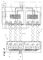
Une deuxième forme (figure 2) serait d'utiliser l'alimentation
locale différemment, c'est-à-dire alimenter les convertisseurs satellites 7
en entrée, du côté des paires torsadées, avec une tension supérieure
(par example +/- 180V ) à celle provenant des convertisseurs centraux
(+/-160V), à travers un pont de diodes supplémentaire. Une forme très
simple du convertisseur principal 1 serait d'utiliser un transformateur de
tension 50/60 Hz ayant une tension secondaire crête à crête de 360 V
AC. En pratique cet exemple de réalisation ne fonctionnerait qu'avec des
réseaux électriques très stables.A second form (Figure 2) would be to use diet
differently, that is to say power the
Il faut noter que la sortie de cette alimentation AC/DC locale devrait respecter en sortie, les contraintes des circuit RFT donc une limitation en courant à maximum (RFT-C) ou en tension et puissance (RFT-V).It should be noted that the output of this local AC / DC power supply should respect in output, the constraints of the circuits RFT thus a limitation to maximum current (RFT-C) or voltage and power (RFT-V).
Cette solution est intéressante car l'énergie consommée par les convertisseurs satellite au repos est fournie par le convertisseur AC/DC local, mais cette deuxième forme nécessite le maintient de la redondance du RPB (satellite), du SOB (central) et des paires torsadées.This solution is interesting because the energy consumed by satellite converters at rest is provided by the converter AC / DC local, but this second form requires the maintenance of the redundancy of the RPB (satellite), the SOB (central) and the twisted pairs.
Une variante de ce dernier montage serait que l'alimentation locale aurait autant de sorties +/- 180V isolées que de télé-alimentations (RPB), de sorte que tous les RPB restent bien indépendants.A variant of this last montage would be that the local power supply would have as many isolated +/- 180V outputs as tele-power supplies (RPB), so that all RPBs remain well independent.
La figure 3 montre une forme selon la figure 1 améliorée au niveau du rendement par l'ajout d'une alimentation auxiliaire locale alimentant les circuits auxiliaires des RPB, principale source de consommation au repos. Elle présente l'avantage de ne pas devoir être conforme aux contraintes des circuits RFT en cas de défaut d'un pont de diode, mais devrait comporter une isolation (galvanique) entre la sortie du convertisseur principal et l'entrée du convertisseur satellite. Cette tension d'alimentation est basse (TBTS) par rapport à la forme selon la figure 2.Figure 3 shows a shape according to Figure 1 improved at the performance level by adding a local auxiliary power supply supplying the auxiliary circuits of the RPBs, the main source of resting consumption. It has the advantage of not having to be in compliance with the constraints of the RFT circuits in the event of a bridge failure diode, but should have (galvanic) isolation between the output of the main converter and the input of the satellite converter. This supply voltage is low (SELV) compared to the shape according to the figure 2.
Pour les trois formes, il est à noter que l'appareil (charge) 6 à alimenter et indiqué dans les revendications fait en particulier référence à un appareil de type DSLAM (Digital Subscriber Line Access Multiplexer).For all three shapes, it should be noted that the device (charge) 6 to feed and indicated in the claims made in particular reference to a DSLAM (Digital Subscriber Line Access) type device Multiplexer).
Le système de télé-alimentation peut être le cas échéant celui décrit dans la demande de brevet européen n° 03391001.9 dont le contenu est incorporé par référence, ainsi que celui décrit dans la demande de brevet européen n° 02077059.0.The remote power system can be if necessary that described in European Patent Application No. 03391001.9, the content is incorporated by reference, as well as that described in the European Patent Application No. 02077059.0.
- 11
- Convertisseur principalMain converter
- 22
- Source d'énergie auxiliaireAuxiliary power source
- 33
- Unité satelliteSatellite unit
- 44
- Module centralCentral module
- 55
- Paire de filsPair of wires
- 66
- Appareil/chargeUnit / load
- 77
- Convertisseurs satellitesSatellite Converters
- 88
- source d'énergie principalemain source of energy
- 99
- source d'énergie disponible au centralsource of energy available at the central office
Claims (8)
Applications Claiming Priority (2)
| Application Number | Priority Date | Filing Date | Title |
|---|---|---|---|
| BE200300589 | 2003-11-03 | ||
| BE200300589 | 2003-11-03 |
Publications (1)
| Publication Number | Publication Date |
|---|---|
| EP1528783A1 true EP1528783A1 (en) | 2005-05-04 |
Family
ID=34397929
Family Applications (1)
| Application Number | Title | Priority Date | Filing Date |
|---|---|---|---|
| EP03447287A Withdrawn EP1528783A1 (en) | 2003-11-03 | 2003-12-10 | Power supply method and apparatus for wired telecommunication systems |
Country Status (1)
| Country | Link |
|---|---|
| EP (1) | EP1528783A1 (en) |
Citations (7)
| Publication number | Priority date | Publication date | Assignee | Title |
|---|---|---|---|---|
| EP0936798A1 (en) * | 1998-02-11 | 1999-08-18 | Sagem Sa | Facsimile with back-up powering of line engagement means |
| EP1161074A1 (en) * | 2000-05-30 | 2001-12-05 | Sagem S.A. | Method for securing a telephone connection |
| EP1176792A1 (en) * | 2000-07-24 | 2002-01-30 | Alcatel | Method and apparatus for providing an all digital loop with power-optimised mode |
| EP1189422A2 (en) * | 2000-08-29 | 2002-03-20 | Lucent Technologies Inc. | System and method for providing lifeline power service to digital subscriber line customers |
| US20020042229A1 (en) * | 2000-10-05 | 2002-04-11 | Alcatel | Terminal adapted to be powered locally and to receive a remote power feed via a link connecting it to a local area network |
| US20020130641A1 (en) * | 2001-03-09 | 2002-09-19 | Schofield Wade S. | Apparatus and method for providing span power to communication equipment at a customer premise |
| US6577882B1 (en) * | 1999-09-24 | 2003-06-10 | Telefonaktiebolaget Lm Ericsson | Arrangement and a method relating to power supply in a communications network |
-
2003
- 2003-12-10 EP EP03447287A patent/EP1528783A1/en not_active Withdrawn
Patent Citations (7)
| Publication number | Priority date | Publication date | Assignee | Title |
|---|---|---|---|---|
| EP0936798A1 (en) * | 1998-02-11 | 1999-08-18 | Sagem Sa | Facsimile with back-up powering of line engagement means |
| US6577882B1 (en) * | 1999-09-24 | 2003-06-10 | Telefonaktiebolaget Lm Ericsson | Arrangement and a method relating to power supply in a communications network |
| EP1161074A1 (en) * | 2000-05-30 | 2001-12-05 | Sagem S.A. | Method for securing a telephone connection |
| EP1176792A1 (en) * | 2000-07-24 | 2002-01-30 | Alcatel | Method and apparatus for providing an all digital loop with power-optimised mode |
| EP1189422A2 (en) * | 2000-08-29 | 2002-03-20 | Lucent Technologies Inc. | System and method for providing lifeline power service to digital subscriber line customers |
| US20020042229A1 (en) * | 2000-10-05 | 2002-04-11 | Alcatel | Terminal adapted to be powered locally and to receive a remote power feed via a link connecting it to a local area network |
| US20020130641A1 (en) * | 2001-03-09 | 2002-09-19 | Schofield Wade S. | Apparatus and method for providing span power to communication equipment at a customer premise |
Similar Documents
| Publication | Publication Date | Title |
|---|---|---|
| EP0578531B1 (en) | Distributed storage non-interruptable power supply system | |
| EP0734111B1 (en) | High voltage photovoltaic energy station using a custom storage means | |
| FR2784517A1 (en) | POWER SUPPLY CIRCUIT FOR A MOTOR VEHICLE EDGE NETWORK WITH TWO DIFFERENT VOLTAGE SUPPLY BRANCHES | |
| EP2820920B1 (en) | Smart portable lighting device | |
| EP2783443B1 (en) | Secured and regulated continuous power supply system with multiple inputs | |
| FR2972581A1 (en) | CHARGE BALANCING SYSTEM FOR BATTERIES | |
| EP2416468A2 (en) | Method for balancing a battery and battery management system implementing such a method | |
| WO2006051178A2 (en) | Self-powered electric charger | |
| FR2976745A1 (en) | SECURE CONTROL MECHANISM FOR DISTRIBUTED PHOTOVOLTAIC SYSTEM | |
| FR2496352A1 (en) | METHOD AND DEVICE FOR CHARGING A BATTERY OF ELECTRIC BATTERIES USING SOLAR CELLS | |
| EP0035727B1 (en) | Power supply system for electronic assemblies | |
| FR3053851A1 (en) | DEVICE FOR CONTROLLING A POWER SYSTEM FOR A FUEL CELL / BATTERY CELL VEHICLE | |
| EP3465861B1 (en) | Method for electrical supply of an apparatus by an autonomous hybrid station | |
| EP2436074B1 (en) | System for shunting cells of a fuel cell | |
| OA11640A (en) | A method of controlling a power station associated with a temporally random power source. | |
| FR2964265A1 (en) | METHOD FOR CHARGING AN ELECTRIC BATTERY | |
| EP1801948A1 (en) | System and method of connection between a first and a second battery and a load | |
| EP1528783A1 (en) | Power supply method and apparatus for wired telecommunication systems | |
| CA2605800A1 (en) | Uninterrupted power supply circuit | |
| EP1040731B1 (en) | Power device for illuminated light box | |
| FR2631753A1 (en) | BATTERY CHARGE REGULATOR FOR PHOTOVOLTAIC GENERATOR | |
| EP1519467B1 (en) | Power supply for an equipment and equipment power supply system | |
| OA21035A (en) | Battery inverter. | |
| EP1177673B1 (en) | Telephone-line based power supply system | |
| WO2023281195A1 (en) | Electrical generator architecture based on a fuel-cell stack and supercapacitors |
Legal Events
| Date | Code | Title | Description |
|---|---|---|---|
| PUAI | Public reference made under article 153(3) epc to a published international application that has entered the european phase |
Free format text: ORIGINAL CODE: 0009012 |
|
| AK | Designated contracting states |
Kind code of ref document: A1 Designated state(s): AT BE BG CH CY CZ DE DK EE ES FI FR GB GR HU IE IT LI LU MC NL PT RO SE SI SK TR |
|
| AX | Request for extension of the european patent |
Extension state: AL LT LV MK |
|
| 17P | Request for examination filed |
Effective date: 20051019 |
|
| AKX | Designation fees paid |
Designated state(s): AT BE BG CH CY CZ DE DK EE ES FI FR GB GR HU IE IT LI LU MC NL PT RO SE SI SK TR |
|
| STAA | Information on the status of an ep patent application or granted ep patent |
Free format text: STATUS: THE APPLICATION IS DEEMED TO BE WITHDRAWN |
|
| 18D | Application deemed to be withdrawn |
Effective date: 20060824 |