EP1528565A1 - Disk recording device and disk recording method - Google Patents
Disk recording device and disk recording method Download PDFInfo
- Publication number
- EP1528565A1 EP1528565A1 EP04022329A EP04022329A EP1528565A1 EP 1528565 A1 EP1528565 A1 EP 1528565A1 EP 04022329 A EP04022329 A EP 04022329A EP 04022329 A EP04022329 A EP 04022329A EP 1528565 A1 EP1528565 A1 EP 1528565A1
- Authority
- EP
- European Patent Office
- Prior art keywords
- recording
- title
- disk
- size
- region
- Prior art date
- Legal status (The legal status is an assumption and is not a legal conclusion. Google has not performed a legal analysis and makes no representation as to the accuracy of the status listed.)
- Withdrawn
Links
- 238000000034 method Methods 0.000 title claims description 19
- 238000007726 management method Methods 0.000 claims abstract description 7
- 230000003287 optical effect Effects 0.000 description 57
- 230000005236 sound signal Effects 0.000 description 11
- 101150032064 VTS1 gene Proteins 0.000 description 8
- 230000008569 process Effects 0.000 description 4
- 230000015572 biosynthetic process Effects 0.000 description 1
- 238000006243 chemical reaction Methods 0.000 description 1
- 230000006835 compression Effects 0.000 description 1
- 238000007906 compression Methods 0.000 description 1
- 230000003247 decreasing effect Effects 0.000 description 1
- 238000010586 diagram Methods 0.000 description 1
- 230000006870 function Effects 0.000 description 1
- 230000006872 improvement Effects 0.000 description 1
- 238000012986 modification Methods 0.000 description 1
- 230000004048 modification Effects 0.000 description 1
- 230000008520 organization Effects 0.000 description 1
- 239000004065 semiconductor Substances 0.000 description 1
- 238000000926 separation method Methods 0.000 description 1
- 230000011664 signaling Effects 0.000 description 1
- 238000003786 synthesis reaction Methods 0.000 description 1
Images


Classifications
-
- G—PHYSICS
- G11—INFORMATION STORAGE
- G11B—INFORMATION STORAGE BASED ON RELATIVE MOVEMENT BETWEEN RECORD CARRIER AND TRANSDUCER
- G11B27/00—Editing; Indexing; Addressing; Timing or synchronising; Monitoring; Measuring tape travel
- G11B27/10—Indexing; Addressing; Timing or synchronising; Measuring tape travel
- G11B27/19—Indexing; Addressing; Timing or synchronising; Measuring tape travel by using information detectable on the record carrier
- G11B27/28—Indexing; Addressing; Timing or synchronising; Measuring tape travel by using information detectable on the record carrier by using information signals recorded by the same method as the main recording
- G11B27/32—Indexing; Addressing; Timing or synchronising; Measuring tape travel by using information detectable on the record carrier by using information signals recorded by the same method as the main recording on separate auxiliary tracks of the same or an auxiliary record carrier
- G11B27/327—Table of contents
- G11B27/329—Table of contents on a disc [VTOC]
-
- G—PHYSICS
- G11—INFORMATION STORAGE
- G11B—INFORMATION STORAGE BASED ON RELATIVE MOVEMENT BETWEEN RECORD CARRIER AND TRANSDUCER
- G11B27/00—Editing; Indexing; Addressing; Timing or synchronising; Monitoring; Measuring tape travel
- G11B27/02—Editing, e.g. varying the order of information signals recorded on, or reproduced from, record carriers
- G11B27/031—Electronic editing of digitised analogue information signals, e.g. audio or video signals
- G11B27/034—Electronic editing of digitised analogue information signals, e.g. audio or video signals on discs
-
- G—PHYSICS
- G11—INFORMATION STORAGE
- G11B—INFORMATION STORAGE BASED ON RELATIVE MOVEMENT BETWEEN RECORD CARRIER AND TRANSDUCER
- G11B27/00—Editing; Indexing; Addressing; Timing or synchronising; Monitoring; Measuring tape travel
- G11B27/10—Indexing; Addressing; Timing or synchronising; Measuring tape travel
- G11B27/102—Programmed access in sequence to addressed parts of tracks of operating record carriers
- G11B27/105—Programmed access in sequence to addressed parts of tracks of operating record carriers of operating discs
-
- G—PHYSICS
- G11—INFORMATION STORAGE
- G11B—INFORMATION STORAGE BASED ON RELATIVE MOVEMENT BETWEEN RECORD CARRIER AND TRANSDUCER
- G11B2220/00—Record carriers by type
- G11B2220/20—Disc-shaped record carriers
- G11B2220/21—Disc-shaped record carriers characterised in that the disc is of read-only, rewritable, or recordable type
- G11B2220/215—Recordable discs
- G11B2220/216—Rewritable discs
-
- G—PHYSICS
- G11—INFORMATION STORAGE
- G11B—INFORMATION STORAGE BASED ON RELATIVE MOVEMENT BETWEEN RECORD CARRIER AND TRANSDUCER
- G11B2220/00—Record carriers by type
- G11B2220/20—Disc-shaped record carriers
- G11B2220/25—Disc-shaped record carriers characterised in that the disc is based on a specific recording technology
- G11B2220/2537—Optical discs
- G11B2220/2562—DVDs [digital versatile discs]; Digital video discs; MMCDs; HDCDs
- G11B2220/2575—DVD-RAMs
-
- G—PHYSICS
- G11—INFORMATION STORAGE
- G11B—INFORMATION STORAGE BASED ON RELATIVE MOVEMENT BETWEEN RECORD CARRIER AND TRANSDUCER
- G11B2220/00—Record carriers by type
- G11B2220/40—Combinations of multiple record carriers
- G11B2220/41—Flat as opposed to hierarchical combination, e.g. library of tapes or discs, CD changer, or groups of record carriers that together store one title
Definitions
- the present invention relates to an improvement of a disk recording device and a disk recording method for recording and erasing titles on, for example, a rewritable optical disk and the like.
- Examples of this type of optical disk include: DVD-ROM (Digital Versatile Disk-Read Only Memory) for playing-only; rewritable DVD-RAM (Random Access Memory); DVD-RW (Rewritable); and DVD-R (Recordable) on which additional recording can be done, and the like.
- DVD-ROM Digital Versatile Disk-Read Only Memory
- rewritable DVD-RAM Random Access Memory
- DVD-RW Real-Rewritable
- DVD-R Recordable
- new DVD video titles are always sequentially recorded from the inner periphery side to the outer periphery side of an optical disk so as to be next to the DVD video title that was recorded last.
- one DVD video title is recorded in a continuous region on the optical disk and then managed.
- the region from which the erased title was recorded is not used for recording the new DVD video title, and because this region remains as an empty region, there is a problem that the recording region in the optical disk is not being effectively used.
- Jpn. Pat. Appln. KOKAI Publication No. 7-175691 discloses a configuration in which a search is done for the largest continuous empty region of a memory data region and a first cluster is set in the center of the empty region so as to perform data recording, and data recording is thereby performed in continuous clusters, and thus time for recording and playing is shortened.
- Jpn. Pat. Appln. KOKAI Publication No. 7-175691 a prerequisite for Jpn. Pat. Appln. KOKAI Publication No. 7-175691 is a recording method in which one group of continuous data is separated into a plurality of clusters and recorded and then managed.
- the recording method is such that one title is recorded in a continuous region on the disk and then managed, and there is no disclosure in this publication with respect to effectively using empty regions that are formed discontinuously on the disk as a result of optional erasing of the plurality of titles recorded on the disk.
- the present invention was conceived in consideration of the above-described situation, and an object thereof is to provide disk recording device and disk recording method in which the recording capacity of the disk is effectively used, by designating the write destination on the disk in accordance with the size of the title to be recorded.
- a disk recording device comprising: recording sections configured to record titles on a disk based on a management method in which additional recording and erasing of each title is possible, and each of the titles are recorded consecutively in a recording region, and the recorded each title is managed by a manager table which corresponds with the title candidate attached before the finalizing processing is carried out; the start position; and size, and in the case where a recorded title is erased, the region where erasure has been done becomes a recordable empty region and reference to the start position and size from the title candidate of the erased title becomes impossible on the manager table; and a first control section configured to designate the appropriate empty region for recording the title for which reserve recording is requested, from the empty regions present on the disk when the reserve recording of the title on the disk has been requested.
- a disk recording method comprising: a first step of recording a title on the disk based on a management method in which additional recording and erasing of each title is possible, and each of the titles are recorded consecutively in a recording region, and the recorded each title is managed by a manager table which corresponds with the title candidate attached before the finalizing processing is carried out; the start position; and size, and in the case where a recorded title is erased, the region where erasure has been done becomes a recordable empty region and reference to the start position and size from the title candidate of the erased title becomes impossible; and a second step of designating an appropriate empty region for recording the title for which reserve recording is requested, from the empty regions present on the disk when the reserve recording of the title on the disk has been requested.
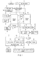
- FIG. 1 shows a disk recording and playing device described in this embodiment.
- the disk recording and playing device herein is one that can use both optical disks including DVD-RW and hard disks as the recording medium, but, for example, semiconductor memory and the like may also be used as the recording medium.
- the disk recording and playing device of FIG. 1 is largely divided into the recording side main block at left of the figure, a playing side main block at right of the figure, and a control side main block at lower part of the figure.
- the disk recording and playing device comprises 2 types of disk drive sections. Firstly it comprises a disk drive section 12 which drives and rotates a optical disk 11 which is a first medium and the information recording medium which can build a video file, and reads and writes information. Also, the disk recording and playing device comprises a HDD (Hard Disk Drive) section 13 which drives the hard disk 13a which is a second medium.
- a HDD Hard Disk Drive
- a D-PRO (Data-Processor) section 14 can supply recording data to the disk drive section 12 and the HDD section 13 and can also receive the played signals.
- the disk drive section 12 comprises a rotation control system, a laser drive system and an optical system for the optical disk 11.
- the D-PRO section 14 handles data for the recording and playing units, and includes a buffer circuit, a modulation/demodulation circuit and an error correction section.
- the main elements comprising the disk recording and playing device are: an encoder section 15 which configures the recording side; a decoder section 16 which configures the playing side; and a microcomputer block 17 which controls the operation of the device main-body.
- the encoder section 15 comprises a video and audio analog/digital converter for converting the inputted analog video signal and analog audio signal to digital signals, a video encoder, and an audio encoder. It also includes a sub picture encoder.
- the output from the encoder section 15 is converted to a prescribed DVD video format at a formatter 19 which includes buffer memory 18 and is supplied to the D-PRO section 14 described above.
- External analog video signal and external analog audio signal obtained from an A/V (Audio Video) input section 20 or analog video signal and analog audio signal obtained from a TV (Television) tuner section 21 are inputted into the encoder section 15.
- the encoder section 15 can supply the compressed digital video signal and the digital audio signal directly to the formatter 19.
- the encoder section 15 can supply the digital video signal and the digital audio signal which has been subjected to analog/digital conversion directly to a V (video) mixing section 22 and an audio selector 23.
- the digital video signal is converted to compressed digital video signal at a variable bit rate based on the MPEG (Moving Picture Experts Group) 2 or MPEG 1 specifications at the video encoder which is included in the encoder section 15.
- the digital audio signal is converted to compressed digital audio signals at a fixed bit rate based on MPEG or AC (Audio Compression)-3 specifications or to linear PCM (Pulse Code Modulation) digital audio signal.
- the sub picture signal of the DVD video signal is encoded at the sub-picuture encoder (run length signaling), and this forms the sub picture bit map.
- the encoded digital video signal, digital audio signal and sub picture data is packed into the video pack, the audio pack and the sub picture pack at the formatter 19, and the packs are collected and converted to a format specified by the DVD video specifications (for example, the specifications recorded on the DVD-RAM, DVD-RW, DVD-R and the like).
- the disk recording and playing device shown in FIG. 1 supplies the information formatted at the formatter 19 (packs of video, audio and sub picture data and the like) and control information that has been created, to the HDD section 13 or the disk drive section 12 via the D-PRO section 14, and the information can be recorded on the hard disk 13a or the optical disk 11.
- the information recorded on the hard disk 13a or the optical disk 11 may be recorded on the optical disk 11 or the hard disk 13a via the D-PRO section 14 and the disk drive section 12.
- the microcomputer block 17 includes a MPU (Micro Processing Unit) 17a, a memory section 17b and a timer section 17c and the like.
- the memory section 17b includes ROM that stores the control programs and the like that the MPU 17a executes, and RAM for supplying the necessary work area for program execution at the MPU 17a.
- the timer section 17c is used for the reserve recording function and the like.
- Execution results of the microcomputer block 17 which must be informed to the user may be displayed at the built-in display section 24 of the disk recording and playing device or by OSD (On Screen Display) at the externally connected monitor display 25. Furthermore, the microcomputer block 17 has a key input section 26 for giving the operation signals for operating the device.
- the timing for the microcomputer block 17 to control the disk drive section 12, the HDD section 13, the D-PRO section 14, the encoder section 15 and the decoder section 16 and the like can be set based on the time data from the STC (System Time Clock) 27.
- the recording and playing operations are usually performed so as to synchronize with the time clock from STC 27, but the other processes may be performed with a timing that is independent of the time clock from STC 27.
- the decoder section 16 comprises: a separator for separating and fetching each packs from the signals of the DVD video format that has pack configuration; memory used at the time pack separation and when other signal processing is performed; a V decoder for decoding the main picture data separated at the separator (contents of the video pack); a SP (Sub Picture) decoder for decoding the sub picture data separated at the separator (contents of the sub picture pack); and an A (Audio) decoder for decoding the audio data separated at the separator (contents of the audio pack). Furthermore, the decoder section 16 comprises a video processor wherein the decoded main picture is appropriately synthesized with the decoded sub picture, and the main picture and sub pictures such as a menu, a highlight button, captions and the like are combined and output.
- the output video signal of the decoder section 16 is input to the V mixing section 22. Synthesis of text data is performed at the V mixing section 22. Furthermore, the line which directly fetches signals from the TV tuner 21 or the A/V input section 20 is also connected to the V mixing section 22.
- a frame memory section 28 which is used as a buffer is connected to the V mixing section 22.
- V mixing section 22 When the output from the V mixing section 22 is analog output, it is output via the I/F (Interface) 29 to the outside, and when the output is digital, it is output via the D/A (Digital/Analog) converter 30 to the external monitor display 25.
- I/F Interface
- D/A Digital/Analog
- the output audio signal of the decoder section 16 is converted to analog at the D/A converter 31 via the selector 23 and output to the externally connected speaker 32.
- the selector 23 is controlled by select signals from the microcomputer block 17. As a result, when the selector 23 directly monitors the digital signal from A/V input section 20 or the TV tuner section 21, the signal that has passed through the encoder section 15 can be selected directly.
- FIG. 2 shows the file system (UDF (Universal Disk Format)-ISO (International Organization for Standardization) 9660) of the optical disk 11 in accordance with DVD video specifications and the arrangement of the DVD video titles.
- UDF Universal Disk Format
- ISO International Organization for Standardization
- the video manager (VMG (Video Manager)) comprises a navigation file (.IFO and .BUP) for managing play control information of the entire optical disk 11 and a presentation file (.VOB) which comprises picture/voice/caption data which form the menu (VMG menu) for selecting a unique DVD video title recorded on the optical disk 11.
- the video title set (VTS (Video Title Set)) comprises a navigation file (.IFO and .BUP) for managing play control information of a title unit and a presentation file (.VOB) which comprises picture/voice/caption data which configures the menu for each video title set (VTS menu) and the title.
- VTS Video Title Set
- a navigation file .IFO and .BUP
- .VOB presentation file
- VTS_01_0.VOB file forms the VTS menu (VTSM) of VTS1
- VTS_01_9.VOB are the files that form the VTS1, and the number of files that form the video title set depends on the size of the title.
- the size of 1 file cannot exceed 1 GB (Giga Byte) because of the limits of the UDF bridge file system.
- the presentation files which form the VTS must be consecutively physically recorded on the optical disk 11. Furthermore, both in the VMG and VTS, a relative positional relationship between the navigation file and the presentation file must be kept.
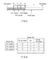
- FIG. 3 shows the state in which a plurality (3 in this case) of the DVD video titles VTS1 to VTS3 are recorded on the optical disk 11.
- the plurality of DVD video titles VTS1 to VTS3 do not have to be consecutively recorded, but normally they are recorded consecutively from the inner periphery side to the outer periphery side of the optical disk 11.
- the title number that is specified by the DVD video specifications is not set until the finalizing processing (processing to make the optical disk 11 playable) has been carried out. For this reason, the recorded DVD video titles VTS1 to VTS3 are managed as title candidates (VTS candidates) until the finalizing processing has been carried out. In other words, the recorded DVD video titles VTS1 to VTS3 are managed as VTS1 to VTS3 candidates that are assigned consecutive numbers from the inner periphery side to the outer periphery side of the optical disk 11.
- FIG. 4 is an example of the title manager table. That is to say, because adding and erasing of the DVD video titles is possible until the finalizing processing has been carried out, recording of the file system is not performed. Because of this, the table for provisionally managing the DVD video titles must be written on the optical disk 11, but this manager table uses a set independent format for each maker.
- the recording destination is at a fixed position in the optical disk 11, or it may be managed by title unit.
- Various types of information are recorded in the manager table in accordance with need, but each title candidate entry is recorded therein.
- the entry is information for referring to the file (data), and includes start address, file size and the like. Also, in order to facilitate management of the manager table, a reference table for making indirect reference possible is provided.
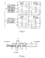
- FIG. 5 shows the state in which an optional recorded DVD video title (VTS2) is erased from the optical disk 11.
- VTS2 an optional recorded DVD video title
- erasure is not erasing the data recorded on the optical disk 11, and can be done by the references being removed from the reference table to the manager table. That is to say, in the embodiment shown in FIG. 5, after the DVD video title (VTS2) is erased, the VTS2 candidate in the reference table refers to the DVD video title (VTS3) which is the VTS3 candidate in the original reference table.
- FIG. 6 shows the effective data arrangement in an optical disk 11 after DVD video title recording and erasing have been carried out repeatedly.
- the front of the erased title is set as the recording destination for the DVD video title that will be recorded next on the optical disk 11.
- FIG. 7 shows the manager table and the reference table in the case where an optional title is erased from among the plurality of DVD video titles recorded on the optical disk 11.
- the reference table is rewritten from the top such that only reference candidates to the effective manager table remain.
- searching for the title candidate that is being referred to at the reference table in the manager table the position and size of the discontinuous empty region formed on the optical disk 11 can be determined and management of recording destination becomes possible.
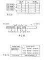
- FIG. 8 shows the state in which a DVD video title is additionally recorded in a prescribed empty region on the optical disk 11.
- the conditions at the time of recording and size of the empty region capacity must be compared and then a determination must be made as to whether or not writing is possible.
- FIG. 9 shows the manager table after the DVD video title is additionally recorded.
- the title entries are used from the entry near the top in the manager table which the erased title used.
- VTS DVD video titles
- the title is recorded in the empty region of size r4.
- w1, r4 and r2 are compared, and if r4 ⁇ w1 ⁇ r2, the title is recorded in the empty region of size r2.
- w1, r2 and r6 are compared, if r2 ⁇ w1 ⁇ r6, the title is recorded in the empty region of size r6.
- recording is controlled so as to be carried out in the empty region having the largest size r6 in the optical disk 11.
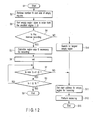
- FIG. 12 is a flowchart showing the operations for designating the empty region where the title will be recorded on the optical disk 11 in accordance with the region size required for recording the title as described above.
- Step S1 when processing begins (Step S1) as a result of a request for a DVD video title to be recorded on the optical disk 11, in Step S2, the microcomputer block 17 obtains information showing the number of empty region N on the optical disk 11 and the sizes thereof from the manager table recorded on the optical disk 11.
- Step S3 the microcomputer block 17 creates a table in which the empty regions on the optical disk 11 are sorted in order from the region E with the smallest size (0) to the region E with the largest size (i), and in Step S4, a determination is made as to whether or not the DVD video title is to be recorded by reserve recording.
- the microcomputer block 17 calculates the region size S necessary for recording the DVD video title in Step S5, and the number i which is assigned in decreasing order of the size of the empty region on the optical disk 11 is set to 0 in Step S6.
- Step 7 the microcomputer block 17 determines whether or not the necessary region size S exceeds the size of the empty region E (i), and in the case where it is determined that this size is exceeded (YES), a determination is made in Step S8 as to whether or not the number i is greater than the number N of empty regions in optical disk 11.
- Step S9 the microcomputer block 17 increases i by 1 and moves to the process of Step S7, and if it is determined that the number i is greater than the number N of empty regions on the optical disk 11 (YES), the process ends (Step S9).
- Step S4 If it is determined in Step S4 above that the DVD video title is not to be recorded by reserve recording (NO), the microcomputer block 17 searches for the largest size empty region on the optical disk 11 in Step S10.
- Step S10 or if it determined in Step S7 above that the necessary region size S does not exceed the size of the empty region E (i) (NO), the microcomputer block 17 sets the empty region for recording in Step 11, and the start address of the empty region is set, and in Step S12, recording of the DVD video title is performed, and the process ends (Step 13).
- the size necessary for recording is calculated and the region for most effective recording is set from among the empty regions as the recording destination, and the case of direct recording the empty region with the largest size is set as the recording destination.
- the recording capacity of the optical disk 11 is effectively used.
- the present invention is not to be limited by the above-described embodiment, and various modifications to the structural elements may be made within the scope of the invention at the stage where the invention is actually implemented. Furthermore by appropriately combining the plurality of structural elements disclosed in this embodiment, various inventions may be created. For example, some structural elements may be eliminated from among the all structural elements disclosed in this embodiment. Furthermore structural elements of different embodiments may be combined.
Landscapes
- Engineering & Computer Science (AREA)
- Multimedia (AREA)
- Management Or Editing Of Information On Record Carriers (AREA)
- Signal Processing For Digital Recording And Reproducing (AREA)
- Indexing, Searching, Synchronizing, And The Amount Of Synchronization Travel Of Record Carriers (AREA)
- Television Signal Processing For Recording (AREA)
Abstract
Recording sections (12, 14, and 15) configured to
record titles on a disk (11) based on a management
method in which additional recording and erasing of
each title is possible, and each of the titles are
recorded consecutively in a recording region, and the
recorded each title is managed by a manager table which
corresponds with the title candidate attached before
the finalizing processing is carried out, the start
position, and size, and in the case where a recorded
title is erased, the region where erasure has been done
becomes a recordable empty region and reference to
the start position and size from the title candidate
of the erased title becomes impossible on the manager
table, and a first control section (17) configured to
designate the appropriate empty region for recording
the title for which reserve recording is requested,
from the empty regions present on the disk (11) when
the reserve recording of the title on the disk (11) has
been requested.
Description
The present invention relates to an improvement
of a disk recording device and a disk recording method
for recording and erasing titles on, for example,
a rewritable optical disk and the like.
As is generally known, there have been advances
in the technology for high density recording of
information, and optical disks having a recording
capacity of 4.7 GB (Giga Bytes) for the layer on one
surface are put to practical use in recent years.
Examples of this type of optical disk include:
DVD-ROM (Digital Versatile Disk-Read Only Memory)
for playing-only; rewritable DVD-RAM (Random Access
Memory); DVD-RW (Rewritable); and DVD-R (Recordable) on
which additional recording can be done, and the like.
However, according to the DVD video specifications,
new DVD video titles are always sequentially
recorded from the inner periphery side to the outer
periphery side of an optical disk so as to be next to
the DVD video title that was recorded last. In this
case, one DVD video title is recorded in a continuous
region on the optical disk and then managed.
In addition, in this type of optical disk, in the
case where the last DVD video title that was recorded
last is erased, the DVD video title that will be
recorded next is overwritten after the DVD video title
recorded before the title that was erased, in other
words, in the regions where the erased DVD video title
was recorded.
Meanwhile, in the case where DVD video titles
other than the DVD video title that was recorded last
is erased, the region from which the erased title was
recorded is not used for recording the new DVD video
title, and because this region remains as an empty
region, there is a problem that the recording region in
the optical disk is not being effectively used.
Jpn. Pat. Appln. KOKAI Publication No. 7-175691
discloses a configuration in which a search is done for
the largest continuous empty region of a memory data
region and a first cluster is set in the center of the
empty region so as to perform data recording, and data
recording is thereby performed in continuous clusters,
and thus time for recording and playing is shortened.
However, a prerequisite for Jpn. Pat. Appln.
KOKAI Publication No. 7-175691 is a recording method in
which one group of continuous data is separated into
a plurality of clusters and recorded and then managed.
According to the specifications for the above-described
DVD video, the recording method is such that one title
is recorded in a continuous region on the disk and then
managed, and there is no disclosure in this publication
with respect to effectively using empty regions that
are formed discontinuously on the disk as a result of
optional erasing of the plurality of titles recorded on
the disk.
The present invention was conceived in consideration
of the above-described situation, and an object
thereof is to provide disk recording device and disk
recording method in which the recording capacity of the
disk is effectively used, by designating the write
destination on the disk in accordance with the size of
the title to be recorded.
According to one aspect of the present invention,
there is provide a disk recording device comprising:
recording sections configured to record titles on a
disk based on a management method in which additional
recording and erasing of each title is possible, and
each of the titles are recorded consecutively in a
recording region, and the recorded each title is
managed by a manager table which corresponds with the
title candidate attached before the finalizing
processing is carried out; the start position; and
size, and in the case where a recorded title is erased,
the region where erasure has been done becomes a
recordable empty region and reference to the start
position and size from the title candidate of the
erased title becomes impossible on the manager table;
and a first control section configured to designate the
appropriate empty region for recording the title for
which reserve recording is requested, from the empty
regions present on the disk when the reserve recording
of the title on the disk has been requested.
According to another aspect of the present
invention, there is provide a disk recording method
comprising: a first step of recording a title on the
disk based on a management method in which additional
recording and erasing of each title is possible, and
each of the titles are recorded consecutively in a
recording region, and the recorded each title is
managed by a manager table which corresponds with the
title candidate attached before the finalizing
processing is carried out; the start position; and
size, and in the case where a recorded title is erased,
the region where erasure has been done becomes a
recordable empty region and reference to the start
position and size from the title candidate of the
erased title becomes impossible; and a second step of
designating an appropriate empty region for recording
the title for which reserve recording is requested,
from the empty regions present on the disk when the
reserve recording of the title on the disk has been
requested.
This summary of the invention does not necessarily
describe all necessary features so that the invention
may also be a sub-combination of these described
features.
The invention can be more fully understood from
the following detailed description when taken in
conjunction with the accompanying drawings, in which:
An embodiment of this invention will be described
with reference to the drawings in the following.
FIG. 1 shows a disk recording and playing device
described in this embodiment. The disk recording and
playing device herein is one that can use both optical
disks including DVD-RW and hard disks as the recording
medium, but, for example, semiconductor memory and the
like may also be used as the recording medium.
In other words, the disk recording and playing
device of FIG. 1 is largely divided into the recording
side main block at left of the figure, a playing side
main block at right of the figure, and a control side
main block at lower part of the figure.
In addition, the disk recording and playing device
comprises 2 types of disk drive sections. Firstly it
comprises a disk drive section 12 which drives and
rotates a optical disk 11 which is a first medium and
the information recording medium which can build a
video file, and reads and writes information. Also,
the disk recording and playing device comprises a HDD
(Hard Disk Drive) section 13 which drives the hard disk
13a which is a second medium.
A D-PRO (Data-Processor) section 14 can supply
recording data to the disk drive section 12 and the HDD
section 13 and can also receive the played signals.
The disk drive section 12 comprises a rotation control
system, a laser drive system and an optical system
for the optical disk 11. The D-PRO section 14 handles
data for the recording and playing units, and includes
a buffer circuit, a modulation/demodulation circuit and
an error correction section.
Furthermore, the main elements comprising the disk
recording and playing device are: an encoder section 15
which configures the recording side; a decoder section
16 which configures the playing side; and a microcomputer
block 17 which controls the operation of the
device main-body.
The encoder section 15 comprises a video and audio
analog/digital converter for converting the inputted
analog video signal and analog audio signal to digital
signals, a video encoder, and an audio encoder.
It also includes a sub picture encoder.
The output from the encoder section 15 is
converted to a prescribed DVD video format at a
formatter 19 which includes buffer memory 18 and is
supplied to the D-PRO section 14 described above.
External analog video signal and external analog
audio signal obtained from an A/V (Audio Video) input
section 20 or analog video signal and analog audio
signal obtained from a TV (Television) tuner section 21
are inputted into the encoder section 15.
It is to be noted that when the compressed digital
video signal and digital audio signal are input
directly, the encoder section 15 can supply the
compressed digital video signal and the digital audio
signal directly to the formatter 19.
Furthermore, the encoder section 15 can supply
the digital video signal and the digital audio signal
which has been subjected to analog/digital conversion
directly to a V (video) mixing section 22 and an audio
selector 23.
The digital video signal is converted to
compressed digital video signal at a variable bit rate
based on the MPEG (Moving Picture Experts Group) 2 or
MPEG 1 specifications at the video encoder which is
included in the encoder section 15. The digital audio
signal is converted to compressed digital audio signals
at a fixed bit rate based on MPEG or AC (Audio
Compression)-3 specifications or to linear PCM (Pulse
Code Modulation) digital audio signal.
When a sub picture signal is input from the A/V
input section 20 (for example, signals from a DVD video
player including an independent output terminal for the
sub picture signal), or when DVD video signal having
such data configuration is broadcast and received at
the TV tuner section 21, the sub picture signal of the
DVD video signal is encoded at the sub-picuture encoder
(run length signaling), and this forms the sub picture
bit map.
The encoded digital video signal, digital audio
signal and sub picture data is packed into the video
pack, the audio pack and the sub picture pack at the
formatter 19, and the packs are collected and converted
to a format specified by the DVD video specifications
(for example, the specifications recorded on the
DVD-RAM, DVD-RW, DVD-R and the like).
At this point, the disk recording and playing
device shown in FIG. 1 supplies the information
formatted at the formatter 19 (packs of video, audio
and sub picture data and the like) and control
information that has been created, to the HDD section
13 or the disk drive section 12 via the D-PRO section
14, and the information can be recorded on the hard
disk 13a or the optical disk 11.
The information recorded on the hard disk 13a or
the optical disk 11 may be recorded on the optical disk
11 or the hard disk 13a via the D-PRO section 14 and
the disk drive section 12.
The microcomputer block 17 includes a MPU (Micro
Processing Unit) 17a, a memory section 17b and a timer
section 17c and the like. The memory section 17b
includes ROM that stores the control programs and the
like that the MPU 17a executes, and RAM for supplying
the necessary work area for program execution at the
MPU 17a. Also the timer section 17c is used for the
reserve recording function and the like.
Execution results of the microcomputer block 17
which must be informed to the user may be displayed at
the built-in display section 24 of the disk recording
and playing device or by OSD (On Screen Display) at the
externally connected monitor display 25. Furthermore,
the microcomputer block 17 has a key input section 26
for giving the operation signals for operating the
device.
It is to be noted that the timing for the microcomputer
block 17 to control the disk drive section 12,
the HDD section 13, the D-PRO section 14, the encoder
section 15 and the decoder section 16 and the like can
be set based on the time data from the STC (System Time
Clock) 27. The recording and playing operations are
usually performed so as to synchronize with the time
clock from STC 27, but the other processes may be
performed with a timing that is independent of the time
clock from STC 27.
The decoder section 16 comprises: a separator for
separating and fetching each packs from the signals of
the DVD video format that has pack configuration;
memory used at the time pack separation and when other
signal processing is performed; a V decoder for
decoding the main picture data separated at the
separator (contents of the video pack); a SP (Sub
Picture) decoder for decoding the sub picture data
separated at the separator (contents of the sub picture
pack); and an A (Audio) decoder for decoding the audio
data separated at the separator (contents of the audio
pack). Furthermore, the decoder section 16 comprises
a video processor wherein the decoded main picture is
appropriately synthesized with the decoded sub picture,
and the main picture and sub pictures such as a menu,
a highlight button, captions and the like are combined
and output.
The output video signal of the decoder section
16 is input to the V mixing section 22. Synthesis of
text data is performed at the V mixing section 22.
Furthermore, the line which directly fetches signals
from the TV tuner 21 or the A/V input section 20 is
also connected to the V mixing section 22.
A frame memory section 28 which is used as
a buffer is connected to the V mixing section 22.
When the output from the V mixing section 22 is analog
output, it is output via the I/F (Interface) 29 to the
outside, and when the output is digital, it is output
via the D/A (Digital/Analog) converter 30 to the
external monitor display 25.
The output audio signal of the decoder section 16
is converted to analog at the D/A converter 31 via the
selector 23 and output to the externally connected
speaker 32. The selector 23 is controlled by select
signals from the microcomputer block 17. As a result,
when the selector 23 directly monitors the digital
signal from A/V input section 20 or the TV tuner
section 21, the signal that has passed through the
encoder section 15 can be selected directly.
FIG. 2 shows the file system (UDF (Universal
Disk Format)-ISO (International Organization for
Standardization) 9660) of the optical disk 11 in
accordance with DVD video specifications and the
arrangement of the DVD video titles.
The video manager (VMG (Video Manager)) comprises
a navigation file (.IFO and .BUP) for managing play
control information of the entire optical disk 11 and a
presentation file (.VOB) which comprises picture/voice/caption
data which form the menu (VMG menu) for
selecting a unique DVD video title recorded on the
optical disk 11.
On the other hand, the video title set (VTS (Video
Title Set)) comprises a navigation file (.IFO and .BUP)
for managing play control information of a title unit
and a presentation file (.VOB) which comprises
picture/voice/caption data which configures the menu
for each video title set (VTS menu) and the title.
Using the VTS1 as an example, the VTS_01_0.VOB
file forms the VTS menu (VTSM) of VTS1, and
VTS_01_1.VOB to VTS_01_9.VOB are the files that form
the VTS1, and the number of files that form the video
title set depends on the size of the title.
The size of 1 file cannot exceed 1 GB (Giga Byte)
because of the limits of the UDF bridge file system.
Also, the presentation files which form the VTS must be
consecutively physically recorded on the optical disk
11. Furthermore, both in the VMG and VTS, a relative
positional relationship between the navigation file and
the presentation file must be kept.
FIG. 3 shows the state in which a plurality (3 in
this case) of the DVD video titles VTS1 to VTS3 are
recorded on the optical disk 11. The plurality of
DVD video titles VTS1 to VTS3 do not have to be
consecutively recorded, but normally they are recorded
consecutively from the inner periphery side to the
outer periphery side of the optical disk 11.
The title number that is specified by the DVD
video specifications is not set until the finalizing
processing (processing to make the optical disk 11
playable) has been carried out. For this reason, the
recorded DVD video titles VTS1 to VTS3 are managed as
title candidates (VTS candidates) until the finalizing
processing has been carried out. In other words, the
recorded DVD video titles VTS1 to VTS3 are managed as
VTS1 to VTS3 candidates that are assigned consecutive
numbers from the inner periphery side to the outer
periphery side of the optical disk 11.
FIG. 4 is an example of the title manager table.
That is to say, because adding and erasing of the
DVD video titles is possible until the finalizing
processing has been carried out, recording of the file
system is not performed. Because of this, the table
for provisionally managing the DVD video titles must be
written on the optical disk 11, but this manager table
uses a set independent format for each maker.
The recording destination is at a fixed position
in the optical disk 11, or it may be managed by title
unit. Various types of information are recorded in the
manager table in accordance with need, but each title
candidate entry is recorded therein. The entry is
information for referring to the file (data), and
includes start address, file size and the like.
Also, in order to facilitate management of the manager
table, a reference table for making indirect reference
possible is provided.
FIG. 5 shows the state in which an optional
recorded DVD video title (VTS2) is erased from the
optical disk 11. When the DVD video title is to be
erased, not only the specific navigation file in the
title or the presentation file is erased, but rather
all the files forming the title are erased.
Normally, erasure is not erasing the data recorded
on the optical disk 11, and can be done by the
references being removed from the reference table to
the manager table. That is to say, in the embodiment
shown in FIG. 5, after the DVD video title (VTS2) is
erased, the VTS2 candidate in the reference table
refers to the DVD video title (VTS3) which is the VTS3
candidate in the original reference table.
FIG. 6 shows the effective data arrangement in
an optical disk 11 after DVD video title recording and
erasing have been carried out repeatedly. In the case
where the DVD video title that was last recorded on
the optical disk 11 is being erased, the front of the
erased title is set as the recording destination for
the DVD video title that will be recorded next on the
optical disk 11.
In addition, when there are a plurality of DVD
video titles that have been recorded, and titles other
than the DVD video title that was recorded last are
to be erased, valid data (titles that have not been
erased) will be present in a discontinuous manner on
the optical disk 11. From the opposite perspective, it
can be said that, there are discontinuous usable empty
regions on the optical disk 11.
FIG. 7 shows the manager table and the reference
table in the case where an optional title is erased
from among the plurality of DVD video titles recorded
on the optical disk 11. The reference table is
rewritten from the top such that only reference
candidates to the effective manager table remain. In
addition, by searching for the title candidate that is
being referred to at the reference table in the manager
table, the position and size of the discontinuous empty
region formed on the optical disk 11 can be determined
and management of recording destination becomes
possible.
FIG. 8 shows the state in which a DVD video title
is additionally recorded in a prescribed empty region
on the optical disk 11. In order to set the
destination for recording, the conditions at the time
of recording and size of the empty region capacity must
be compared and then a determination must be made as to
whether or not writing is possible.
FIG. 9 shows the manager table after the DVD video
title is additionally recorded. The title entries are
used from the entry near the top in the manager table
which the erased title used. According to specification,
a maximum of 99 DVD video titles (VTS) can be
stored in the optical disk 11 and thus 99 title entries
can be managed inside the manager table.
If as shown in FIG. 10 for example, there are 3
empty regions on the optical disk 11, and the relationship
of the size of each empty regions is such that r4
< r2 < r6. In this case, when the necessary region
size for title recording is determined in advance based
on picture quality, sound quality and recording time
as in the case of reserved recording, or when the
recording conditions are not known as in the case of
direct recording, the recording destination is changed
as shown in FIG. 11.
That is to say, in the reserved recording, in
the case where the size of the region required for
recording the title is w1, w1 and r4 are compared and
if w1 < r4, the title is recorded in the empty region
of size r4. Also, w1, r4 and r2 are compared, and if
r4 < w1 < r2, the title is recorded in the empty region
of size r2. Furthermore, when w1, r2 and r6 are
compared, if r2 < w1 < r6, the title is recorded in the
empty region of size r6.
If the required region size for recording the
title is not known in advance as in the case of direct
recording, recording is controlled so as to be carried
out in the empty region having the largest size r6 in
the optical disk 11.
FIG. 12 is a flowchart showing the operations for
designating the empty region where the title will be
recorded on the optical disk 11 in accordance with
the region size required for recording the title as
described above.
First, when processing begins (Step S1) as
a result of a request for a DVD video title to be
recorded on the optical disk 11, in Step S2, the
microcomputer block 17 obtains information showing the
number of empty region N on the optical disk 11 and the
sizes thereof from the manager table recorded on the
optical disk 11.
In addition, in Step S3, the microcomputer block
17 creates a table in which the empty regions on the
optical disk 11 are sorted in order from the region E
with the smallest size (0) to the region E with the
largest size (i), and in Step S4, a determination is
made as to whether or not the DVD video title is to be
recorded by reserve recording.
If it is determined that the DVD video title is
to be recorded by reserve recording (YES), the
microcomputer block 17 calculates the region size S
necessary for recording the DVD video title in Step S5,
and the number i which is assigned in decreasing order
of the size of the empty region on the optical disk 11
is set to 0 in Step S6.
Subsequently, in Step 7, the microcomputer block
17 determines whether or not the necessary region size
S exceeds the size of the empty region E (i), and in
the case where it is determined that this size is
exceeded (YES), a determination is made in Step S8 as
to whether or not the number i is greater than the
number N of empty regions in optical disk 11.
In addition, if it is determined that the number i
is not greater than the number N of empty regions on
the optical disk 11 (NO), the microcomputer block 17
increases i by 1 and moves to the process of Step S7,
and if it is determined that the number i is greater
than the number N of empty regions on the optical disk
11 (YES), the process ends (Step S9).
If it is determined in Step S4 above that the DVD
video title is not to be recorded by reserve recording
(NO), the microcomputer block 17 searches for the
largest size empty region on the optical disk 11 in
Step S10.
After Step S10, or if it determined in Step S7
above that the necessary region size S does not exceed
the size of the empty region E (i) (NO), the microcomputer
block 17 sets the empty region for recording
in Step 11, and the start address of the empty region
is set, and in Step S12, recording of the DVD video
title is performed, and the process ends (Step 13).
According to the above-described embodiment,
in the case of reserve recording, the size necessary
for recording is calculated and the region for most
effective recording is set from among the empty regions
as the recording destination, and the case of direct
recording the empty region with the largest size is set
as the recording destination. Thus in the method in
which one DVD video title is recorded in a continuous
region on the optical disk 11 and then managed, the
recording capacity of the optical disk 11 is
effectively used.
It is to be noted that the present invention is
not to be limited by the above-described embodiment,
and various modifications to the structural elements
may be made within the scope of the invention at the
stage where the invention is actually implemented.
Furthermore by appropriately combining the plurality
of structural elements disclosed in this embodiment,
various inventions may be created. For example, some
structural elements may be eliminated from among the
all structural elements disclosed in this embodiment.
Furthermore structural elements of different
embodiments may be combined.
Although the present invention has been described using a
DVD as an example for the realization of the present invention
it should be stressed that the present invention is not
limited to this kind of information storage medium and that
other kinds of information storage media not fulfilling the
DVD specification can be used to implement the concept of the
present invention as well.
Claims (14)
- A disk recording device characterized by comprising:recording sections (12, 14, and 15) configured to record titles on a disk (11) based on a management method in which additional recording and erasing of each title is possible, and each of the titles are recorded consecutively in a recording region, and the recorded each title is managed by a manager table which corresponds with the title candidate attached before the finalizing processing is carried out; the start position; and size, and in the case where a recorded title is erased, the region where erasure has been done becomes a recordable empty region and reference to the start position and size from the title candidate of the erased title becomes impossible on the manager table; anda first control section (17) configured to designate the appropriate empty region for recording the title for which reserve recording is requested, from the empty regions present on the disk (11) when the reserve recording of the title on the disk (11) has been requested.
- A disk recording device according to claim 1, characterized in that the first control section (17) comprises:a calculation section (17) configured to calculate the size of the recording region necessary for recording the title when reserve recording of the title has been requested for the disk (11); anda designation section (17) configured to designate the appropriate empty region for recording the title for which the reserve recording is requested, from the empty regions present on the disk (11) based on the size calculated at the calculation section (17).
- A disc recording device according to claim 1, characterized in that the first control section (17) comprises:a retrieval section (17) configured to retrieve information showing the start position and size of all recordable empty regions present on the disk (11) from the disk (11);a calculation section (17) configured to calculate the size of the necessary recording region size based on recording conditions for the title, when reserve recording of the title has been requested for the disk (11); anda designation section (17) configured to designate the empty region for recording the title for which the reserve recording is requested, by comparing the size calculated at the calculation section (17) with the size of the empty region retrieved at the retrieval section (17).
- A disk recording device according to claim 3, characterized in that the designation section (17) designates the empty region with the smallest size of the empty regions with a size that is larger than the size calculated at the calculation section (17) from among the empty regions present on the disk (11).
- A disk recording device according to claim 3, characterized in that the designation section (17) sequentially compares the size calculated at the calculation section (17) starting with the region with the smallest size from among the empty regions obtained at the retrieval section (17), and designates the empty regions with a size greater than the size first calculated at the calculation section (17).
- A disk recording device according to claim 1, characterized by further comprising a second control section (17) configured to designate the empty region with the largest size on the disk (11) as the recording destination for the title requested by the direct recording, when direct recording of a title has been requested for the disk (11).
- A disk recording device according to claim 1, characterized by further comprising a second control section (17) configured to designate the empty region with the largest size retrieved at the retrieval section (17) as the recording destination of the title for which direct recording is requested, when direct recording of the title has been requested for the disk (11).
- A disk recording method characterized by comprising:a first step (12, 14, and 15) of recording a title on the disk (11) based on a management method in which additional recording and erasing of each title is possible, and each of the titles are recorded consecutively in a recording region, and the recorded each title is managed by a manager table which corresponds with the title candidate attached before the finalizing processing is carried out; the start position; and size, and in the case where a recorded title is erased, the region where erasure has been done becomes a recordable empty region and reference to the start position and size from the title candidate of the erased title becomes impossible; anda second step (S4 to S8, S11) of designating an appropriate empty region for recording the title for which reserve recording is requested, from the empty regions present on the disk (11) when the reserve recording of the title on the disk (11) has been requested.
- A disk recording method according to claim 8, characterized in that the second step (S4 to S8, S11) comprises:calculating the size of the recording region necessary for recording the title when reserve recording of the title has been requested for the disk (11) (S5); anddesignating an appropriate empty region for recording the title for which the reserve recording is requested, from the empty regions present on the disk (11) based on the calculated size (S7, S8 and S11).
- A disk recording method according to claim 8, characterized in that the second step (S4 to S8, S11) comprises:retrieving information showing the start position and size of all recordable empty regions present on the disk (11) from the disk (11) (S2);calculating the size of the necessary recording region based on the recording conditions for the title when reserve recording of the title has been requested for the disk (11) (S5); andcomparing the calculated size with the retrieved size of the empty region and designates the empty region for recording the title for which the reserve recording is requested (S7, S8, and S11).
- A disk recording method according claim 10, characterized in that the designating the empty region for recording the title for which the reserve recording is requested (S7, S8, and S11) comprises:designating the empty region with the smallest size of those empty regions with a size larger than the calculated size from among the empty regions present on the disk (11).
- A disk recording method according claim 10, characterized in that the designating the empty region for recording the title for which reserve recording is requested (S7, S8, and S11) comprises:sequentially comparing the calculated size starting with the region with the smallest size from among the retrieved empty region sizes (S7, S8); anddesignating the empty regions larger in size than the size first calculated from among the sizes of the empty regions (S7, S11).
- A disk recording method according to claim 8, characterized by further comprising:a third step (S10, S11) of designating the empty region with the largest size on the disk (11) as the recording destination of the title for which direct recording is requested, when the direct recording of the title has been requested for the disk (11).
- A disk recording method according to claim 8, characterized by further comprising:a third step (S10, S11) of designating the retrieved empty region with the largest size as the recording destination of the title for which direct recording is requested, when direct recording of the title has been requested for the disk.
Applications Claiming Priority (2)
| Application Number | Priority Date | Filing Date | Title |
|---|---|---|---|
| JP2003369309A JP2005135489A (en) | 2003-10-29 | 2003-10-29 | Disc recording apparatus and disc recording method |
| JP2003369309 | 2003-10-29 |
Publications (1)
| Publication Number | Publication Date |
|---|---|
| EP1528565A1 true EP1528565A1 (en) | 2005-05-04 |
Family
ID=34420175
Family Applications (1)
| Application Number | Title | Priority Date | Filing Date |
|---|---|---|---|
| EP04022329A Withdrawn EP1528565A1 (en) | 2003-10-29 | 2004-09-20 | Disk recording device and disk recording method |
Country Status (3)
| Country | Link |
|---|---|
| US (1) | US7477578B2 (en) |
| EP (1) | EP1528565A1 (en) |
| JP (1) | JP2005135489A (en) |
Families Citing this family (3)
| Publication number | Priority date | Publication date | Assignee | Title |
|---|---|---|---|---|
| JP2009266292A (en) * | 2008-04-24 | 2009-11-12 | Toshiba Corp | Recording/reproducing device and recording method |
| JP2011135393A (en) * | 2009-12-25 | 2011-07-07 | Hitachi Consumer Electronics Co Ltd | Recorder and recording method |
| CN120962151B (en) * | 2025-10-20 | 2026-02-03 | 北京金橙子科技股份有限公司 | Multi-equipment big data content optimization processing method |
Citations (3)
| Publication number | Priority date | Publication date | Assignee | Title |
|---|---|---|---|---|
| EP0333165A2 (en) * | 1988-03-16 | 1989-09-20 | Matsushita Electric Industrial Co., Ltd. | System for managing recording areas on writable type optical disk |
| EP0905699A2 (en) * | 1997-09-17 | 1999-03-31 | Matsushita Electric Industrial Co., Ltd | Optical disc recording apparatus, computer-readable recording medium recording a file management program, and optical disc |
| US20010015944A1 (en) * | 1997-05-19 | 2001-08-23 | Sony Corporation | Recording method and apparatus for continuous playback of fragmented signals |
Family Cites Families (8)
| Publication number | Priority date | Publication date | Assignee | Title |
|---|---|---|---|---|
| US5687397A (en) * | 1993-02-26 | 1997-11-11 | Sony Corporation | System for expansion of data storage medium to store user data |
| JP2938732B2 (en) * | 1993-11-10 | 1999-08-25 | 松下電送システム株式会社 | Memory management device and facsimile device using the same |
| JPH07175691A (en) | 1994-12-19 | 1995-07-14 | Olympus Optical Co Ltd | Information handler |
| DE69636648T2 (en) * | 1995-04-14 | 2007-12-06 | Kabushiki Kaisha Toshiba, Kawasaki | Apparatus for reproducing from a recording medium |
| JP3069324B2 (en) | 1997-09-17 | 2000-07-24 | 松下電器産業株式会社 | Optical disk recording device, recording method, and program recording medium |
| JPH11232792A (en) | 1998-02-12 | 1999-08-27 | Nippon Columbia Co Ltd | Recording device and disk recording method |
| JP4470308B2 (en) | 2000-09-27 | 2010-06-02 | ソニー株式会社 | Voice information processing apparatus and method |
| JP4216687B2 (en) * | 2003-10-16 | 2009-01-28 | 株式会社東芝 | Disc playback apparatus and disc playback method |
-
2003
- 2003-10-29 JP JP2003369309A patent/JP2005135489A/en active Pending
-
2004
- 2004-09-17 US US10/943,208 patent/US7477578B2/en not_active Expired - Fee Related
- 2004-09-20 EP EP04022329A patent/EP1528565A1/en not_active Withdrawn
Patent Citations (3)
| Publication number | Priority date | Publication date | Assignee | Title |
|---|---|---|---|---|
| EP0333165A2 (en) * | 1988-03-16 | 1989-09-20 | Matsushita Electric Industrial Co., Ltd. | System for managing recording areas on writable type optical disk |
| US20010015944A1 (en) * | 1997-05-19 | 2001-08-23 | Sony Corporation | Recording method and apparatus for continuous playback of fragmented signals |
| EP0905699A2 (en) * | 1997-09-17 | 1999-03-31 | Matsushita Electric Industrial Co., Ltd | Optical disc recording apparatus, computer-readable recording medium recording a file management program, and optical disc |
Also Published As
| Publication number | Publication date |
|---|---|
| US7477578B2 (en) | 2009-01-13 |
| US20060062121A1 (en) | 2006-03-23 |
| JP2005135489A (en) | 2005-05-26 |
Similar Documents
| Publication | Publication Date | Title |
|---|---|---|
| JP3607486B2 (en) | Information recording / reproducing device | |
| JP3631430B2 (en) | Recording / playback device with automatic chapter creation function | |
| WO1999038168A1 (en) | Recording media, and recording / reproducing apparatus | |
| EP1205934A2 (en) | Recording/reproducing apparatus | |
| JP3637275B2 (en) | Information immediate recording apparatus and information immediate recording method | |
| US20050100308A1 (en) | Image editing apparatus and image editing method | |
| JP2002152665A (en) | Recording / playback device with playlist creation guide function | |
| US7477578B2 (en) | Disk recording device and disk recording method for recording and erasing titles on a disk | |
| US20070003225A1 (en) | Method and apparatus for recording information and playback information | |
| US20020131189A1 (en) | Method and apparatus for image recording and reproduction for plurality of media | |
| JP2003151244A (en) | Image recording / reproducing device having remaining amount display function and image recording / reproducing method | |
| US7266067B2 (en) | Disk reproducing apparatus and disk reproducing method | |
| US7783166B1 (en) | Recording medium, and system and method for recording and reproducing the recording medium | |
| US20060285828A1 (en) | Video recording apparatus and video recording method | |
| US7869698B2 (en) | Information recording/playback method and recording/playback apparatus | |
| JP3607596B2 (en) | Recording / playback device with chapter creation guide function | |
| JP3917610B2 (en) | Recording / playback device with chapter creation guide function | |
| JP2006185499A (en) | Data recording method, data recording apparatus, and imaging apparatus | |
| JP3735616B2 (en) | Video information processing apparatus and video information processing method | |
| JP4247094B2 (en) | Information recording / reproducing apparatus and method | |
| JP2004364325A (en) | Automatic chapter thumbnail creation method | |
| JP3881676B2 (en) | Optical disc, information reproducing apparatus, information recording apparatus and method | |
| JP2001076462A (en) | Information recording medium and information recording / reproducing device | |
| JP2009266292A (en) | Recording/reproducing device and recording method | |
| JP2006323895A (en) | Playback method and playback device according to media type |
Legal Events
| Date | Code | Title | Description |
|---|---|---|---|
| PUAI | Public reference made under article 153(3) epc to a published international application that has entered the european phase |
Free format text: ORIGINAL CODE: 0009012 |
|
| 17P | Request for examination filed |
Effective date: 20040920 |
|
| AK | Designated contracting states |
Kind code of ref document: A1 Designated state(s): AT BE BG CH CY CZ DE DK EE ES FI FR GB GR HU IE IT LI LU MC NL PL PT RO SE SI SK TR |
|
| AX | Request for extension of the european patent |
Extension state: AL HR LT LV MK |
|
| AKX | Designation fees paid |
Designated state(s): DE FR GB |
|
| STAA | Information on the status of an ep patent application or granted ep patent |
Free format text: STATUS: THE APPLICATION IS DEEMED TO BE WITHDRAWN |
|
| 18D | Application deemed to be withdrawn |
Effective date: 20100120 |