EP1528389A1 - Verfahren und Vorrichtung zur ultrahochempfindlichen optischen Detektion von biologischen und chemischen Mitteln - Google Patents
Verfahren und Vorrichtung zur ultrahochempfindlichen optischen Detektion von biologischen und chemischen Mitteln Download PDFInfo
- Publication number
- EP1528389A1 EP1528389A1 EP04014191A EP04014191A EP1528389A1 EP 1528389 A1 EP1528389 A1 EP 1528389A1 EP 04014191 A EP04014191 A EP 04014191A EP 04014191 A EP04014191 A EP 04014191A EP 1528389 A1 EP1528389 A1 EP 1528389A1
- Authority
- EP
- European Patent Office
- Prior art keywords
- cavity resonator
- optical cavity
- waveguide
- optical
- thin metal
- Prior art date
- Legal status (The legal status is an assumption and is not a legal conclusion. Google has not performed a legal analysis and makes no representation as to the accuracy of the status listed.)
- Withdrawn
Links
- 230000003287 optical effect Effects 0.000 title claims description 29
- 238000000034 method Methods 0.000 title claims description 15
- 238000001514 detection method Methods 0.000 title claims description 12
- 230000035945 sensitivity Effects 0.000 title abstract description 9
- 239000003124 biologic agent Substances 0.000 title description 4
- 239000013043 chemical agent Substances 0.000 title description 4
- 239000002184 metal Substances 0.000 claims description 28
- 229910052751 metal Inorganic materials 0.000 claims description 28
- 239000012491 analyte Substances 0.000 claims description 27
- 238000010168 coupling process Methods 0.000 claims description 25
- 238000005859 coupling reaction Methods 0.000 claims description 25
- 230000008878 coupling Effects 0.000 claims description 21
- 230000002463 transducing effect Effects 0.000 claims description 19
- 239000000758 substrate Substances 0.000 claims description 12
- VYPSYNLAJGMNEJ-UHFFFAOYSA-N Silicium dioxide Chemical compound O=[Si]=O VYPSYNLAJGMNEJ-UHFFFAOYSA-N 0.000 claims description 9
- 230000001427 coherent effect Effects 0.000 claims description 6
- 229910052681 coesite Inorganic materials 0.000 claims description 4
- 229910052906 cristobalite Inorganic materials 0.000 claims description 4
- 239000000377 silicon dioxide Substances 0.000 claims description 4
- 229910052682 stishovite Inorganic materials 0.000 claims description 4
- 229910052905 tridymite Inorganic materials 0.000 claims description 4
- 238000000151 deposition Methods 0.000 claims 1
- 238000002198 surface plasmon resonance spectroscopy Methods 0.000 abstract description 16
- 239000000126 substance Substances 0.000 abstract description 14
- 238000000180 cavity ring-down spectroscopy Methods 0.000 abstract description 5
- 238000013459 approach Methods 0.000 abstract description 3
- 238000010521 absorption reaction Methods 0.000 description 13
- 230000008859 change Effects 0.000 description 12
- 230000005684 electric field Effects 0.000 description 10
- 238000005259 measurement Methods 0.000 description 10
- 230000000694 effects Effects 0.000 description 6
- 230000005284 excitation Effects 0.000 description 4
- 239000010408 film Substances 0.000 description 4
- PCHJSUWPFVWCPO-UHFFFAOYSA-N gold Chemical compound [Au] PCHJSUWPFVWCPO-UHFFFAOYSA-N 0.000 description 4
- 229910052737 gold Inorganic materials 0.000 description 4
- 239000010931 gold Substances 0.000 description 4
- BQCADISMDOOEFD-UHFFFAOYSA-N Silver Chemical compound [Ag] BQCADISMDOOEFD-UHFFFAOYSA-N 0.000 description 3
- 238000005452 bending Methods 0.000 description 3
- 238000006243 chemical reaction Methods 0.000 description 3
- 238000012986 modification Methods 0.000 description 3
- 230000004048 modification Effects 0.000 description 3
- 238000012552 review Methods 0.000 description 3
- 229910052709 silver Inorganic materials 0.000 description 3
- 239000004332 silver Substances 0.000 description 3
- 230000005641 tunneling Effects 0.000 description 3
- 239000003574 free electron Substances 0.000 description 2
- 239000000463 material Substances 0.000 description 2
- 230000010355 oscillation Effects 0.000 description 2
- 238000001228 spectrum Methods 0.000 description 2
- 239000012780 transparent material Substances 0.000 description 2
- 238000012935 Averaging Methods 0.000 description 1
- 238000004458 analytical method Methods 0.000 description 1
- 230000015572 biosynthetic process Effects 0.000 description 1
- 230000001419 dependent effect Effects 0.000 description 1
- 238000003618 dip coating Methods 0.000 description 1
- 239000005350 fused silica glass Substances 0.000 description 1
- 239000011521 glass Substances 0.000 description 1
- 108091008039 hormone receptors Proteins 0.000 description 1
- 230000003993 interaction Effects 0.000 description 1
- 239000003446 ligand Substances 0.000 description 1
- 230000031700 light absorption Effects 0.000 description 1
- 230000007774 longterm Effects 0.000 description 1
- 238000004519 manufacturing process Methods 0.000 description 1
- 238000013507 mapping Methods 0.000 description 1
- 239000011159 matrix material Substances 0.000 description 1
- 230000007246 mechanism Effects 0.000 description 1
- 238000012544 monitoring process Methods 0.000 description 1
- 230000003647 oxidation Effects 0.000 description 1
- 238000007254 oxidation reaction Methods 0.000 description 1
- 230000010287 polarization Effects 0.000 description 1
- 229920000642 polymer Polymers 0.000 description 1
- 238000012545 processing Methods 0.000 description 1
- 230000009467 reduction Effects 0.000 description 1
- 238000005070 sampling Methods 0.000 description 1
- 230000003595 spectral effect Effects 0.000 description 1
- 238000004611 spectroscopical analysis Methods 0.000 description 1
- 238000004528 spin coating Methods 0.000 description 1
- 230000003746 surface roughness Effects 0.000 description 1
- 230000002459 sustained effect Effects 0.000 description 1
- 239000010409 thin film Substances 0.000 description 1
- 239000013598 vector Substances 0.000 description 1
- 238000002460 vibrational spectroscopy Methods 0.000 description 1
Images



Classifications
-
- G—PHYSICS
- G01—MEASURING; TESTING
- G01N—INVESTIGATING OR ANALYSING MATERIALS BY DETERMINING THEIR CHEMICAL OR PHYSICAL PROPERTIES
- G01N21/00—Investigating or analysing materials by the use of optical means, i.e. using sub-millimetre waves, infrared, visible or ultraviolet light
- G01N21/17—Systems in which incident light is modified in accordance with the properties of the material investigated
- G01N21/55—Specular reflectivity
- G01N21/552—Attenuated total reflection
- G01N21/553—Attenuated total reflection and using surface plasmons
-
- G—PHYSICS
- G01—MEASURING; TESTING
- G01J—MEASUREMENT OF INTENSITY, VELOCITY, SPECTRAL CONTENT, POLARISATION, PHASE OR PULSE CHARACTERISTICS OF INFRARED, VISIBLE OR ULTRAVIOLET LIGHT; COLORIMETRY; RADIATION PYROMETRY
- G01J3/00—Spectrometry; Spectrophotometry; Monochromators; Measuring colours
- G01J3/28—Investigating the spectrum
- G01J3/42—Absorption spectrometry; Double beam spectrometry; Flicker spectrometry; Reflection spectrometry
-
- G—PHYSICS
- G01—MEASURING; TESTING
- G01N—INVESTIGATING OR ANALYSING MATERIALS BY DETERMINING THEIR CHEMICAL OR PHYSICAL PROPERTIES
- G01N21/00—Investigating or analysing materials by the use of optical means, i.e. using sub-millimetre waves, infrared, visible or ultraviolet light
- G01N21/17—Systems in which incident light is modified in accordance with the properties of the material investigated
- G01N21/25—Colour; Spectral properties, i.e. comparison of effect of material on the light at two or more different wavelengths or wavelength bands
- G01N21/31—Investigating relative effect of material at wavelengths characteristic of specific elements or molecules, e.g. atomic absorption spectrometry
- G01N21/39—Investigating relative effect of material at wavelengths characteristic of specific elements or molecules, e.g. atomic absorption spectrometry using tunable lasers
Definitions
- a surface plasmon is a localized oscillation of free electrons on the metal surface.
- the light absorption characteristics of the surface plasmon resonance depend sensitively on the dielectric constant near the metal surface.
- a chemical reaction occurring at the metal surface modifies the local dielectric environment resulting in a change in the absorption characteristics of the resonance.
- ring-down spectroscopy techniques are combined with surface plasmon resonance detection to allow ultra-sensitive chemical analysis in conjunction with an optical source.
- This allows improved chemical sensors with higher sensitivities than conventional surface plasmon techniques.
- the enhanced sensitivity allows use of smaller sample sizes and the ability to detect smaller concentrations of the chemical substances of interest.
- FIG. 1 shows cavity ring-down spectrophotometer (CRDS) 100 in an embodiment in accordance with the invention.
- CRDS 100 uses total internal reflection (TIR) to improve the cavity efficiency and provides for the presence of evanescent waves 140, 150, 160 and 170.
- TIR total internal reflection
- ring cavity resonator 115 in FIG. 1 has a square shape other polygonal shapes such as hexagons or octagons, for example, may also be used as a ring cavity resonator in embodiments in accordance with the invention. Polygonal shapes with more sides such as hexagonal and octagonal ring cavity resonators typically are more difficult to fabricate.
- a stable ring cavity resonator supports one or more low-diffraction modes which are self-reproducing after one round-trip pass through the resonator.
- ring cavity resonator 115 is borderline unstable if all faces 145, 155, 165 and 175 are plane parallel. If one of faces 145, 155, 165 and 175 is a convex face, stability is induced and diffraction losses are significantly reduced. Typically, either face 145 or 155 is chosen to be convex in accordance with the invention.
- a typical material for CRDS 100 in the near-infrared is fused-silica.
- fluoride-doped glasses In mid infrared applications involving vibrational spectroscopy, fluoride-doped glasses have low bulk attenuation coefficients of L bulk ⁇ 1 • 10 -7 /cm or less. This low bulk attenuation has the potential for permitting individual molecule detection by cavity ring-down spectroscopy as described by Pipino et al. in "Evanescent wave cavity ring-down spectroscopy with a total-internal-reflection minicavity", in Reviews of Scientific Instruments, 68, 8, August 1997, p.2978, incorporated by reference in its entirety.
- the ultimate sensitivity of CRDS 100 and CRDS 200 see FIGs.
- TIR Direct coupling of free-space waves cannot typically be achieved when cavity modes are sustained totally by TIR.
- a consequence of TIR is the generation of evanescent waves 140, 150, 160, 170 which are required to satisfy the boundary conditions imposed by Maxwell's equations for light incident from a denser medium at an angle that exceeds the critical angle.
- the presence of evanescent waves 160 and 170 allows probing of region 166 and 177 in FIG. 1.
- the broadband nature of TIR removes the bandwidth restrictions that are characteristic of the dielectric mirrors of non-TIR CRDS.
- tunable laser 105 is typically used to generate light pulse 180 which is totally reflected by totally reflecting prism 110 creating evanescent wave 140.
- Evanescent wave 140 excites the stable modes of TIR ring cavity resonator 115 through photon tunneling or frustrated total internal reflection.
- totally reflecting prism 110 is placed in close proximity to TIR cavity resonator 115 so that the evanescent field is phase matched to the modes of TIR cavity resonator 115.
- totally reflecting prism 120 is placed in close proximity to TIR cavity resonator 115 to allow evanescent out coupling via totally reflecting prism 120 using evanescent wave 150.
- a gap width will exist where the coupling loss equals the total round-trip loss of TIR cavity resonator 115 and providing impedance matched coupling.
- the coupling loss equals the total round-trip loss of TIR cavity resonator 115 and providing impedance matched coupling.
- over coupling occurs which reduces the finesse (or Q) of TIR cavity resonator 115.
- coupling efficiency plateaus as the maximum finesse of TIR cavity resonator 115 is approached.
- weaker coupling is preferred because it allows higher finesse.
- signal levels may be improved through multiple mode excitation or mode-matched cw excitation, as described, for example, by Mweijer and Engeln in Chemical Physics Letters, 262, 105, 1995.
- L diff depends on cavity size through stability factors and apertures associated with the finite facet dimensions.
- L bulk 2 ⁇ r 0 n sin( ⁇ / n) where ⁇ is the bulk attenuation coefficient.
- Faces 165 and 175 of TIR cavity resonator 115 are the locations of thin metal layers 167 and 177 used for the surface plasmon resonance (SPR) detection.
- a plasmon is an inhomogenous solution to the electromagnetic wave equation that is highly sensitive to the local dielectric environment.
- Thin layer of metal (typically silver or gold) layers 167 and 177 typically having a thickness on the order of nanometers, are deposited on faces 165 and 175 in accordance with the invention. Silver typically suffers from long term stability problems due to oxidation.
- the p-polarized component of evanescent waves 160 and 170 interacts with the free electrons on the surface of thin metal layers 167 and 177.
- (1)) is shorter the greater the plasmon loss, L plasmon , and is a direct measurement of the plasmon absorption coefficient.
- n is the number of sides of TIR cavity resonator
- d is the effective sampling depth of the evanescent wave
- ⁇ plasmon ( ⁇ ) is the absorption cross-section as a function of frequency for the surface plasmon
- h is the thickness of the thin metal layer
- a sample medium relating to a chemical or biological reaction may be sensed using CRDS 100.
- a transducing layer typically having a thickness of about 1 ⁇ m, is deposited onto thin metal layers 167 and 177 on faces 165 and 175, respectively.
- Transducing layers are typically formed from polymers and applied using spin coating or dip coating techniques in chemical sensing applications. The transducing layer adsorbs or chemically reacts with the analyte or chemical to be detected.
- the transducing medium is typically formed as a matrix or layer of biomolecules which are capable of binding the analyte molecules 166.
- biomolecular interactions may be used including antigen-antibody, receptor-ligand and hormone-receptor binding.
- the presence of analyte 166 changes the local dielectric constant on faces 165 and 175.
- the change in local dielectric constant effects the plasmon absorption coefficient resulting in a change in the value of the photon decay time ⁇ ( ⁇ ) through L plasmon .
- the photon decay rate or ring down time is first measured for CRDS 100 in the absence of the analyte or chemical to be detected but with thin metal layers 167 and 177 and the transducing layers present.
- the light from tunable laser 105 excites a surface plasmon resonance and depending on the frequency, a certain fraction of the light is absorbed.
- the photon decay rate ⁇ ( ⁇ ) of cavity resonator 115 and the finesse are inversely proportional to the fraction of light absorbed.
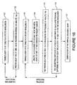
- FIG. 1b shows the steps for an embodiment in accordance with the invention for mapping the change in the surface plasmon resonance coefficient in the presence of analyte 166 as a function of the frequency of tunable laser 105.
- tunable laser 105 is tuned to a specified wavelength ⁇ 1 .
- the photon decay time of CRDS 100 is first measured in the absence of analyte 166.
- step 131 may be repeated multiple times to obtain an average to reduce any noise.
- Steps 131 and 132 are repeated with the next wavelength ⁇ i until CRDS 100 has been calibrated over the wavelength range ⁇ 1 ... ⁇ n of interest.
- laser 105 is tuned to wavelength ⁇ 1 .
- step 134 analyte 166 is allowed to interact with thin metal films 167 and 177 and the transducing layer on located each thin metal film 167 and 177.
- step 135 the photon decay time for CRDS 100 is measured in the presence of analyte 166.
- step 135 may be repeated multiple times to obtain an average to reduce noise.
- step 136 the absorption coefficient at a particular wavelength is calculated from the difference in photon decay time of CRDS 100 at a particular wavelength in the absence of analyte 166 and in the presence of analyte 166.
- Steps 133 through 136 are repeated with the next wavelength ⁇ i until the absorption coefficient as a function of wavelength has been mapped over the wavelength range ⁇ 1 ... ⁇ n of interest.
- step 137 the chemical or biological is identified based on the results from step 136.
- a difference in the photon decay rate typically indicates the presence of a particular chemical or biological agent, even at very low concentrations.
- Relative uncertainties in photon decay time of 0.2% are reported by Pipino et al. in "Evanescent wave cavity ring-down spectroscopy with a total-internal-reflection minicavity", in Reviews of Scientific Instruments, 68, 8, August 1997, p2978, enabling sensitivities on the order of parts per 10 10 or better to be achieved.
- the accessibility to such high sensitivity measurements allows the presence of very low concentrations to be detected using ring-down techniques. Measurement of changes involves the measurement of a decay rate and therefore is not sensitive to laser intensity noise and is shot-noise limited. However, the photon decay must be sufficiently long such that accurate digitization of the decay curve can be obtained.
- FIG. 2a shows a top view of planar cavity ring-down spectrophotometer (CRDS) 200 in accordance with the invention.
- Planar CRDS 200 is configured as a planar lightwave circuit allowing compact, cheap and integrated sensors and may be made using well-known methods adapted from the making of planar lightwave circuits.
- Planar waveguides 210, 211 and ring cavity resonator 215 are created in substrate 205 (see FIG. 2b), typically made from SiO 2 . Note that waveguide 210 is adiabatically tapered to mode-match ring cavity resonator 215. This provides for low coupling loss while maintaining high finesse.
- planar waveguide 210 Light from typically a tunable laser source propagates in planar waveguide 210 and couples to ring cavity resonator 215 via an evanescent wave that excites the stable modes of ring cavity resonator 215 through photon tunneling or, equivalently, frustrated total reflection.
- planar waveguide 210 is separated from ring cavity resonator 215 by gap d 1 so that the evanescent field is phase matched to the modes of ring cavity resonator 215.
- Planar waveguide 210 coupling to ring cavity resonator 215 is adjusted by changing the gap d 1 .
- Efficient coupling is achieved when the gap d 1 is on the order of the 1/e decay length of the confined electric field in planar waveguide 210. This is known as the impedance matched condition because the light round trip loss in ring cavity resonator 215 is equal to the coupling loss into ring cavity resonator 215 from planar waveguide 210.
- the largest finesse for ring cavity resonator 215 is not obtained by operating at the most efficient gap d 1 .
- the finesse for ring cavity resonator 215 is typically selected to obtain optimum signal-to-noise for a chosen electronic detection scheme.
- the finesse is selected such that that the photn decay time or ring-down time matches the electronic detector bandwidth.
- Outcoupling from ring cavity resonator 215 to a detector is typically accomplished by planar waveguide 211 whose coupling to ring cavity resonator 215 is adjusted by changing gap d 2 .
- both incoupling and outcoupling may be accomplished using planar waveguide 210 without waveguide 211.
- the electronic detector (not shown) measures the time dependence of the outcoupled signal which allows determination of the photon decay time.
- FIG. 2b shows a side view of planar CRDS 200.
- the top portion of substrate 205 has been etched down and is coated with thin metal layer 245, typically silver or gold, to enable surface plasmon resonance formation.
- thin metal layer 245, typically silver or gold is deposited onto thin metal layer 245.
- the photon decay rate or ring down time is first measured for CRDS 200 in the absence of the analyte or chemical to be detected.
- Analyte 250 is then deposited on the transducing layer (not shown) resulting in a change of the effective dielectric constant in the region above thin metal layer 245 if the substance of interest is present.
- the ring down time for CRDS 200 is modified by the change in the dielectric constant.
- the change in local dielectric constant effects the plasmon absorption coefficient resulting in a change in the value of the photon decay time ⁇ ( ⁇ ).
- the substrate material beneath ring cavity resonator 245 is sufficiently thick to prevent evanescent coupling out the bottom of substrate 205 and any resulting effects on the ring down time.
- the bending loss, L bending gives the loss due to the radius of curvature of ring cavity resonator 215 and is given by: where and n r is the refractive index of ring cavity resonator 215, a is the waveguide width, a / w is the transverse 1/e decay length of the waveguide electric field, w is the exponential decay constant and determines the decay rate of the electric field outside of waveguide 210, ⁇ is the wavelength of the incident light, R is the radius of ring cavity resonator 215 and E(r) is the electric field.
- Planar CRDS 200 operating in the near infrared where SiO 2 has a bulk-loss L bulk ⁇ 5 • 10 -7 /cm, allows absorption measurements less than ⁇ 10 -10 to be achieved as disclosed in Pipino et al. in "Evanescent wave cavity ring-down spectroscopy with a total-internal-reflection minicavity", in Reviews of Scientific Instruments, 68, 8, August 1997, p.2978.
- ultra-high Q toroid microcavities see "Utra-high- Q toroid microcavity on a chip" by Armani et al. in NATURE, vol. 421, February 27 2003, p. 925, incorporated herein by reference.
- planar waveguide 210 and ring cavity resonator 215 take planar waveguide 210 and ring cavity resonator 215 to have a refractive index 0.3% different from substrate 205.
- planar waveguide 210 Take planar waveguide 210 to have a cross-section of 8 ⁇ m by 8 ⁇ m adiabatically tapering to a cross-section of 3.6 ⁇ m by 3.6 ⁇ m
- planar waveguide 211 to have a cross-section of 8 ⁇ m by 8 ⁇ m
- ring cavity resonator 215 have a radius of 20 ⁇ m
- substrate 205 to have a thickness of 24 ⁇ m
- the finesse of the above configuration for CRDS 200 is about 1.2 • 10 8 .
- Adding thin metal layer 245 as a 50nm gold film reduces the finesse to about 2.5 • 10 7 .
- Applying a transducing layer having a thickness of 1 ⁇ m and having n refractive index 1.4 on thin metal layer 245, further lowers the finesse to about 2.1 • 10 7 .
- the cavity Q is lowered to about 9.8 • 10 6 .
- the Q for CRDS 200 is about 2.0 • 10 8 using the values above.
- Adding thin metal layer 245 as a thin 50nm gold film reduces the finesse to 4.2 • 10 7 .
- Applying a transducing layer having a thickness of 1 ⁇ m and having n refractive index 1.4 on thin metal layer 245, further lowers the cavity Q for CRDS 200 to about 3.4 • 10 7 .
- the cavity Q for CRDS 200 is lowered to about 2.7 • 10 7 .
- the cavity Q of CRDS 200 is large enough to allow precision measurement of the photon decay time.
- the fractional uncertainty in photon decay time ⁇ / ⁇ may be reduced to about 0.5%.
- the minimum detectable absorption is ⁇ / ⁇ • L bulk ⁇ 10 -10 .
- the presence of analyte 250 changes the local dielectric constant on top surface 249 of CRDS 200.
- the change in local dielectric constant effects the plasmon absorption coefficient resulting in a change in the value of the photon decay time ⁇ ( ⁇ ) through L plasmon .
- the photon decay rate or ring down time is first measured for CRDS 200 in the absence of the analyte or chemical to be detected but with thin metal layer 245 and the transducing layer present.
- the light from a tunable laser (not shown) excites a surface plasmon resonance and depending on the frequency, a certain fraction of the light is absorbed.
- the photon decay rate ⁇ ( ⁇ ) of CRDS 200 and the finesse are inversely proportional to the fraction of light absorbed.
- top surface 249 of CRDS 200 is exposed to analyte 250, the chemical or biological agent to be sensed.
- analyte 250 interacts with the transducing layer, the local dielectric constant is modified in the vicinity of the surface plasmon.
- the difference between the photon decay time in the absence and presence of analyte 250 is proportional to the concentration of analyte 250 through the plasmon loss term of Eq. (5).
- the change in the surface plasmon resonance coefficient in the presence of analyte 250 may be mapped as a function of frequency of the tunable laser in analogy to the discussion above with reference to FIG. 1b.
Landscapes
- Physics & Mathematics (AREA)
- Spectroscopy & Molecular Physics (AREA)
- General Physics & Mathematics (AREA)
- Health & Medical Sciences (AREA)
- Life Sciences & Earth Sciences (AREA)
- Chemical & Material Sciences (AREA)
- Analytical Chemistry (AREA)
- Biochemistry (AREA)
- General Health & Medical Sciences (AREA)
- Immunology (AREA)
- Pathology (AREA)
- Optics & Photonics (AREA)
- Investigating Or Analysing Materials By Optical Means (AREA)
Applications Claiming Priority (2)
| Application Number | Priority Date | Filing Date | Title |
|---|---|---|---|
| US698589 | 2000-10-27 | ||
| US10/698,589 US7054009B2 (en) | 2003-10-31 | 2003-10-31 | Method and apparatus for ultra-high sensitivity optical detection of biological and chemical agents |
Publications (1)
| Publication Number | Publication Date |
|---|---|
| EP1528389A1 true EP1528389A1 (de) | 2005-05-04 |
Family
ID=34423419
Family Applications (1)
| Application Number | Title | Priority Date | Filing Date |
|---|---|---|---|
| EP04014191A Withdrawn EP1528389A1 (de) | 2003-10-31 | 2004-06-17 | Verfahren und Vorrichtung zur ultrahochempfindlichen optischen Detektion von biologischen und chemischen Mitteln |
Country Status (3)
| Country | Link |
|---|---|
| US (1) | US7054009B2 (de) |
| EP (1) | EP1528389A1 (de) |
| CN (1) | CN1611927A (de) |
Cited By (5)
| Publication number | Priority date | Publication date | Assignee | Title |
|---|---|---|---|---|
| WO2008054170A1 (en) * | 2006-11-03 | 2008-05-08 | Chung-Ang University Industry-Academy Cooperation Foundation | Micro resonator sensor |
| KR100839967B1 (ko) | 2006-11-17 | 2008-06-19 | 중앙대학교 산학협력단 | 전반사미러의 표면 플라즈몬 공명을 이용한 마이크로공진기 센서 |
| WO2009074933A1 (en) * | 2007-12-13 | 2009-06-18 | Koninklijke Philips Electronics N. V. | Biosensor based on frustrated total internal reflection |
| EP3074756A4 (de) * | 2013-11-27 | 2017-06-28 | Baker Hughes Incorporated | Schätzung von materialeigenschaften mittels interner reflektanzspektroskopie |
| CN113518585A (zh) * | 2019-02-28 | 2021-10-19 | 贝鲁特美国大学 | 生物标志物监测传感器及使用方法 |
Families Citing this family (17)
| Publication number | Priority date | Publication date | Assignee | Title |
|---|---|---|---|---|
| GB0405820D0 (en) * | 2004-03-15 | 2004-04-21 | Evanesco Ltd | Time resolved and multiplexed cavity sensing apparatus and methods |
| US20050238078A1 (en) * | 2004-04-23 | 2005-10-27 | Pipino Andrew C | Optical resonator produced by optical contacting to join optical elements and use thereof, for example, for chemical and biochemical detection in liquids |
| US7336859B2 (en) * | 2005-12-28 | 2008-02-26 | Honeywell International, Inc. | Sensor using ultra thin waveguides and optical fibers |
| US7375808B2 (en) * | 2006-09-28 | 2008-05-20 | The United States Of America As Represented By The Administrator Of The National Aeronautics And Space Administration | Method and system for sensing and identifying foreign particles in a gaseous environment |
| US7668420B2 (en) * | 2007-07-26 | 2010-02-23 | Hewlett-Packard Development Company, L.P. | Optical waveguide ring resonator with an intracavity active element |
| US7630603B2 (en) * | 2007-07-26 | 2009-12-08 | Hewlett-Packard Development Company, L.P. | Optical waveguide ring resonator with photo-tunneling input/output port |
| US8385698B2 (en) * | 2007-12-12 | 2013-02-26 | Hewlett-Packard Development Company, L.P. | Controllable optical ring resonator having periodically spaced control electrodes |
| CN101556243B (zh) * | 2008-04-09 | 2012-06-13 | 台达电子工业股份有限公司 | 生物感测器 |
| WO2010128395A1 (en) * | 2009-05-04 | 2010-11-11 | Theodore Peter Rakitzis | Intra-cavity ellipsometer system and method |
| US9903805B2 (en) | 2014-05-08 | 2018-02-27 | Theodore Peter Rakitzis | Cavity enhanced polarimeter and related methods |
| US9702812B2 (en) * | 2014-05-08 | 2017-07-11 | Theodore Peter Rakitzis | Cavity enhanced polarimeter and related methods |
| US10352974B2 (en) * | 2016-06-22 | 2019-07-16 | Commissariat A L'energie Atomique Et Aux Energies Alternatives | Method and apparatus to implement frequency stabilization of a resonator |
| EP3500892A4 (de) | 2016-08-18 | 2020-04-08 | The Regents of The University of California | Komplettmikrowellenstabilisierung von mikroresonatorbasierten optischen frequenzkämmen |
| WO2018081824A1 (en) * | 2016-10-31 | 2018-05-03 | The Regents Of The University Of California | Adiabatic dispersion-managed frequency comb generation |
| WO2019046645A1 (en) | 2017-08-30 | 2019-03-07 | The Regents Of The University Of California | Graphene microcavity frequency combs and related methods of manufacturing |
| EP3821505A4 (de) * | 2018-07-13 | 2022-07-06 | The Government of the United States of America as represented by the Secretary of the Navy | Hochstabile halbleiterlaser und sensoren für iii-v- und silicium-photonische integrierte schaltungen |
| US12174016B2 (en) | 2018-11-06 | 2024-12-24 | The Regents Of The University Of California | Chip-scale frequency-comb assisted coherent lidar ranging with sub-micrometer precision |
Citations (2)
| Publication number | Priority date | Publication date | Assignee | Title |
|---|---|---|---|---|
| US5835231A (en) * | 1997-10-31 | 1998-11-10 | The United States Of America As Represented By The Secretary Of Commerce | Broad band intra-cavity total reflection chemical sensor |
| US20020122179A1 (en) * | 2001-01-10 | 2002-09-05 | Pipino Andrew C.R. | Sensitive and selective chemical sensor with nanostructured surfaces |
Family Cites Families (2)
| Publication number | Priority date | Publication date | Assignee | Title |
|---|---|---|---|---|
| US4297035A (en) | 1979-09-14 | 1981-10-27 | International Business Machines Corporation | Method and device for detecting a specific spectral feature |
| FR2716973B1 (fr) | 1994-03-03 | 1996-06-07 | Schlumberger Ind Sa | Procédé et dispositif de détermination de l'absorption d'un rayonnement électromagnétique par un gaz. |
-
2003
- 2003-10-31 US US10/698,589 patent/US7054009B2/en not_active Expired - Fee Related
-
2004
- 2004-06-17 EP EP04014191A patent/EP1528389A1/de not_active Withdrawn
- 2004-08-20 CN CNA2004100582992A patent/CN1611927A/zh active Pending
Patent Citations (2)
| Publication number | Priority date | Publication date | Assignee | Title |
|---|---|---|---|---|
| US5835231A (en) * | 1997-10-31 | 1998-11-10 | The United States Of America As Represented By The Secretary Of Commerce | Broad band intra-cavity total reflection chemical sensor |
| US20020122179A1 (en) * | 2001-01-10 | 2002-09-05 | Pipino Andrew C.R. | Sensitive and selective chemical sensor with nanostructured surfaces |
Non-Patent Citations (1)
| Title |
|---|
| PIPINO A C R ET AL: "EVANESCENT WAVE CAVITY RING-DOWN SPECTROSCOPY WITH A TOTAL- INTERNAL-REFLECTION MINICAVITY", REVIEW OF SCIENTIFIC INSTRUMENTS, AMERICAN INSTITUTE OF PHYSICS. NEW YORK, US, vol. 68, no. 8, 1 August 1997 (1997-08-01), pages 2978 - 2989, XP000723516, ISSN: 0034-6748 * |
Cited By (8)
| Publication number | Priority date | Publication date | Assignee | Title |
|---|---|---|---|---|
| WO2008054170A1 (en) * | 2006-11-03 | 2008-05-08 | Chung-Ang University Industry-Academy Cooperation Foundation | Micro resonator sensor |
| KR100839969B1 (ko) | 2006-11-03 | 2008-06-19 | 중앙대학교 산학협력단 | 마이크로 공진기 센서 |
| US7612887B2 (en) | 2006-11-03 | 2009-11-03 | Chung-An University Industry-Academy Cooperation Foundation | Micro resonator sensor |
| CN101346614B (zh) * | 2006-11-03 | 2010-11-10 | 中央大学校产学协力团 | 微谐振器传感器 |
| KR100839967B1 (ko) | 2006-11-17 | 2008-06-19 | 중앙대학교 산학협력단 | 전반사미러의 표면 플라즈몬 공명을 이용한 마이크로공진기 센서 |
| WO2009074933A1 (en) * | 2007-12-13 | 2009-06-18 | Koninklijke Philips Electronics N. V. | Biosensor based on frustrated total internal reflection |
| EP3074756A4 (de) * | 2013-11-27 | 2017-06-28 | Baker Hughes Incorporated | Schätzung von materialeigenschaften mittels interner reflektanzspektroskopie |
| CN113518585A (zh) * | 2019-02-28 | 2021-10-19 | 贝鲁特美国大学 | 生物标志物监测传感器及使用方法 |
Also Published As
| Publication number | Publication date |
|---|---|
| CN1611927A (zh) | 2005-05-04 |
| US7054009B2 (en) | 2006-05-30 |
| US20050094150A1 (en) | 2005-05-05 |
Similar Documents
| Publication | Publication Date | Title |
|---|---|---|
| US7054009B2 (en) | Method and apparatus for ultra-high sensitivity optical detection of biological and chemical agents | |
| US9285534B2 (en) | Fiber-optic surface plasmon resonance sensor and sensing method using the same | |
| Slavı́k et al. | Single-mode optical fiber surface plasmon resonance sensor | |
| Pipino et al. | Evanescent wave cavity ring-down spectroscopy with a total-internal-reflection minicavity | |
| US6421128B1 (en) | Coupled plasmon-waveguide resonance spectroscopic device and method for measuring film properties in the ultraviolet and infrared special ranges | |
| EP0677735B1 (de) | Vorrichtung und Verfahren zur intrakavitären Messung der makroskopischen Eigenschaften von Chemikalien | |
| EP0677734B1 (de) | Nachweis einer Zielsubstanz in einer Probe | |
| Sharma et al. | Fiber-optic sensors based on surface plasmon resonance: a comprehensive review | |
| JP2002505425A (ja) | 導波路構造 | |
| US8711356B2 (en) | Gas sensor with a porous layer that detectably affects a surface lattice resonant condition of a nanoparticle array | |
| US6330387B1 (en) | Coupled plasmon-waveguide resonance spectroscopic device and method for measuring film properties in the ultraviolet and infrared spectral ranges | |
| US20080008418A1 (en) | Coupling light into microresonators | |
| EP1846750A1 (de) | Cavity ring-down -nachweis von oberflächenplasmonresonanz in einem optischen faserresonator | |
| JP2010511872A (ja) | 光検出装置及び方法 | |
| US6992770B2 (en) | Sensor utilizing attenuated total reflection | |
| Shakoor et al. | One-dimensional silicon nitride grating refractive index sensor suitable for integration with CMOS detectors | |
| EP2252876A1 (de) | Obeflächenplasmon-erzeugungsvorrichtung, sensor und/oder probenanalysegerät damit sowie verfahren zur erzeugung von oberflächenplasmonen und wahrnehmung und/oder analyse von proben | |
| US20070159633A1 (en) | Enhanced surface plasmon resonance sensor using Goos-Hanchen effect | |
| Baets et al. | Spectroscopy-on-chip applications of silicon photonics | |
| WO2006122402A1 (en) | Plasmon-polariton refractive-index fiber bio-sensor with fiber bragg grating | |
| US6731388B1 (en) | Method of measuring surface plasmon resonance using interference structure of reflected beam profile | |
| Gupta | Surface plasmon resonance based fiber optic sensors | |
| Beam et al. | Planar fiber-optic chips for broadband spectroscopic interrogation of thin films | |
| Ševo | Investigation of novel interrogation methods for guided-mode-resonance biosensors | |
| Erim et al. | Biosensing with asymmetric high refractive index contrast gratings |
Legal Events
| Date | Code | Title | Description |
|---|---|---|---|
| PUAI | Public reference made under article 153(3) epc to a published international application that has entered the european phase |
Free format text: ORIGINAL CODE: 0009012 |
|
| AK | Designated contracting states |
Kind code of ref document: A1 Designated state(s): AT BE BG CH CY CZ DE DK EE ES FI FR GB GR HU IE IT LI LU MC NL PL PT RO SE SI SK TR |
|
| AX | Request for extension of the european patent |
Extension state: AL HR LT LV MK |
|
| 17P | Request for examination filed |
Effective date: 20051006 |
|
| AKX | Designation fees paid |
Designated state(s): DE ES FR GB IT |
|
| 17Q | First examination report despatched |
Effective date: 20061214 |
|
| RAP1 | Party data changed (applicant data changed or rights of an application transferred) |
Owner name: AGILENT TECHNOLOGIES, INC. |
|
| STAA | Information on the status of an ep patent application or granted ep patent |
Free format text: STATUS: THE APPLICATION IS DEEMED TO BE WITHDRAWN |
|
| 18D | Application deemed to be withdrawn |
Effective date: 20070425 |