EP1528311A2 - Tripod assembly - Google Patents
Tripod assembly Download PDFInfo
- Publication number
- EP1528311A2 EP1528311A2 EP04025870A EP04025870A EP1528311A2 EP 1528311 A2 EP1528311 A2 EP 1528311A2 EP 04025870 A EP04025870 A EP 04025870A EP 04025870 A EP04025870 A EP 04025870A EP 1528311 A2 EP1528311 A2 EP 1528311A2
- Authority
- EP
- European Patent Office
- Prior art keywords
- legs
- head
- support assembly
- base
- neck
- Prior art date
- Legal status (The legal status is an assumption and is not a legal conclusion. Google has not performed a legal analysis and makes no representation as to the accuracy of the status listed.)
- Withdrawn
Links
- 230000001681 protective effect Effects 0.000 description 2
- 238000010276 construction Methods 0.000 description 1
- 230000000994 depressogenic effect Effects 0.000 description 1
- 238000000034 method Methods 0.000 description 1
Images


Classifications
-
- F—MECHANICAL ENGINEERING; LIGHTING; HEATING; WEAPONS; BLASTING
- F16—ENGINEERING ELEMENTS AND UNITS; GENERAL MEASURES FOR PRODUCING AND MAINTAINING EFFECTIVE FUNCTIONING OF MACHINES OR INSTALLATIONS; THERMAL INSULATION IN GENERAL
- F16M—FRAMES, CASINGS OR BEDS OF ENGINES, MACHINES OR APPARATUS, NOT SPECIFIC TO ENGINES, MACHINES OR APPARATUS PROVIDED FOR ELSEWHERE; STANDS; SUPPORTS
- F16M11/00—Stands or trestles as supports for apparatus or articles placed thereon ; Stands for scientific apparatus such as gravitational force meters
- F16M11/20—Undercarriages with or without wheels
- F16M11/24—Undercarriages with or without wheels changeable in height or length of legs, also for transport only, e.g. by means of tubes screwed into each other
- F16M11/242—Undercarriages with or without wheels changeable in height or length of legs, also for transport only, e.g. by means of tubes screwed into each other by spreading of the legs
-
- F—MECHANICAL ENGINEERING; LIGHTING; HEATING; WEAPONS; BLASTING
- F16—ENGINEERING ELEMENTS AND UNITS; GENERAL MEASURES FOR PRODUCING AND MAINTAINING EFFECTIVE FUNCTIONING OF MACHINES OR INSTALLATIONS; THERMAL INSULATION IN GENERAL
- F16M—FRAMES, CASINGS OR BEDS OF ENGINES, MACHINES OR APPARATUS, NOT SPECIFIC TO ENGINES, MACHINES OR APPARATUS PROVIDED FOR ELSEWHERE; STANDS; SUPPORTS
- F16M11/00—Stands or trestles as supports for apparatus or articles placed thereon ; Stands for scientific apparatus such as gravitational force meters
- F16M11/02—Heads
- F16M11/04—Means for attachment of apparatus; Means allowing adjustment of the apparatus relatively to the stand
- F16M11/041—Allowing quick release of the apparatus
-
- F—MECHANICAL ENGINEERING; LIGHTING; HEATING; WEAPONS; BLASTING
- F16—ENGINEERING ELEMENTS AND UNITS; GENERAL MEASURES FOR PRODUCING AND MAINTAINING EFFECTIVE FUNCTIONING OF MACHINES OR INSTALLATIONS; THERMAL INSULATION IN GENERAL
- F16M—FRAMES, CASINGS OR BEDS OF ENGINES, MACHINES OR APPARATUS, NOT SPECIFIC TO ENGINES, MACHINES OR APPARATUS PROVIDED FOR ELSEWHERE; STANDS; SUPPORTS
- F16M11/00—Stands or trestles as supports for apparatus or articles placed thereon ; Stands for scientific apparatus such as gravitational force meters
- F16M11/02—Heads
- F16M11/16—Details concerning attachment of head-supporting legs, with or without actuation of locking members thereof
-
- F—MECHANICAL ENGINEERING; LIGHTING; HEATING; WEAPONS; BLASTING
- F16—ENGINEERING ELEMENTS AND UNITS; GENERAL MEASURES FOR PRODUCING AND MAINTAINING EFFECTIVE FUNCTIONING OF MACHINES OR INSTALLATIONS; THERMAL INSULATION IN GENERAL
- F16M—FRAMES, CASINGS OR BEDS OF ENGINES, MACHINES OR APPARATUS, NOT SPECIFIC TO ENGINES, MACHINES OR APPARATUS PROVIDED FOR ELSEWHERE; STANDS; SUPPORTS
- F16M11/00—Stands or trestles as supports for apparatus or articles placed thereon ; Stands for scientific apparatus such as gravitational force meters
- F16M11/20—Undercarriages with or without wheels
- F16M11/24—Undercarriages with or without wheels changeable in height or length of legs, also for transport only, e.g. by means of tubes screwed into each other
- F16M11/26—Undercarriages with or without wheels changeable in height or length of legs, also for transport only, e.g. by means of tubes screwed into each other by telescoping, with or without folding
- F16M11/28—Undercarriages for supports with one single telescoping pillar
-
- F—MECHANICAL ENGINEERING; LIGHTING; HEATING; WEAPONS; BLASTING
- F16—ENGINEERING ELEMENTS AND UNITS; GENERAL MEASURES FOR PRODUCING AND MAINTAINING EFFECTIVE FUNCTIONING OF MACHINES OR INSTALLATIONS; THERMAL INSULATION IN GENERAL
- F16M—FRAMES, CASINGS OR BEDS OF ENGINES, MACHINES OR APPARATUS, NOT SPECIFIC TO ENGINES, MACHINES OR APPARATUS PROVIDED FOR ELSEWHERE; STANDS; SUPPORTS
- F16M13/00—Other supports for positioning apparatus or articles; Means for steadying hand-held apparatus or articles
-
- G—PHYSICS
- G01—MEASURING; TESTING
- G01C—MEASURING DISTANCES, LEVELS OR BEARINGS; SURVEYING; NAVIGATION; GYROSCOPIC INSTRUMENTS; PHOTOGRAMMETRY OR VIDEOGRAMMETRY
- G01C15/00—Surveying instruments or accessories not provided for in groups G01C1/00 - G01C13/00
- G01C15/002—Active optical surveying means
Definitions
- the present invention relates to a tripod assembly and more particularly to a folding tripod assembly.
- tripod is not new in the art, and the basic principle involved with its use is fairly simple- three legs used to provide a stable platform.
- the potential applications for tripods are numerous, although one common use is as a portable stand for a device or tool.
- tripods are used in applications ranging from supporting a laser sight for surveying, a camera for photography, a telescope for sky viewing, and an antenna in communication systems.
- a tripod assembly having a base and a head mounted to the base.
- a plurality of legs are coupled to the base and are moveable between an open position and a closed position.
- the plurality of legs form a tripod to support the base and head in an upright position when the legs are in the open position.
- the plurality of legs at least partially enclose the base and the head when in the closed position.
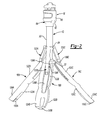
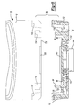
- the tripod assembly 10 includes a base 12, a neck portion 14 extending from the base 12, a head 16 removably coupled to an end of the neck portion 14, and three legs 18A, 18B, and 18C extending out from the base 12.
- the base 12 generally includes a hollow cylindrical body 20 with a cap 22 mounted on an end thereof. At an end 26 of the cylindrical body 20 opposite the cap 22, the cylindrical body 20 is open for receiving the neck 14.
- a collar 24 is mounted around the cylindrical body 20. The collar 24 and the cap 22 cooperate to allow movement of the three legs 18A, 18B, 18C as will also be described in greater detail below.
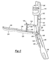
- the neck 14 telescopes between an extended position as shown in Figure 1 and a collapsed position as shown in Figure 2.
- the neck 14 includes a plurality of segments 30A, 30B, 30C, 30D, and 30E.
- the segments 30A-E are each hollow cylinders and are sized such that one of the segments 30A-E fits within another such that the neck 14 may be extended or collapsed.
- segment 30A has an outer circumference less than an inner circumference of the hollow cylindrical body 20 of the base 12
- segment 30B has an outer circumference less than an inner circumference of 30A, and so on such that segment 30E has an outer circumference less than an inner circumference of segment 30D.
- the segments 30A-E are held in place in the extended position by a detent system common to each of the segments 30A-E and the hollow cylindrical tube 20.
- this detent system indicated generally by reference numeral 32, will be described with reference to the hollow cylindrical tube 20 and segment 30A.
- the detent system 34 is used with all the segments 30A-E.
- segment 30A fits within the open end 26 of the hollow cylindrical tube 20.
- the hollow cylindrical tube 20 has a first detent 34 and a second detent 36 formed therein near the open end 26.
- the detents 34, 36 are formed around the entire circumference of the hollow cylindrical tube 20 and are spaced such that they are proximate to one another.
- a sheath 38 fits within the open end 26 and is held in place by a third detent 40 that engages a groove 42 formed in the sheath 38.
- the sheath 38 is sized to receive segment 30A.
- Segment 30A includes an end cap 44 coupled to an end of segment 30A located within the hollow cylindrical tube 20.
- the end cap 44 is held in place by a detent 46 formed in segment 30A that engages a groove 48 formed in the end cap 44.
- the end cap 44 includes a plurality of tabs 50, three in the example provided, that extend out from segment 30A.
- Each tab 50 includes a head portion 52 sized such that it engages an inner surface 54 of the hollow cylindrical tube 20.
- segments 30A-E of the neck 14 are in an extended position when the head portions 52 are located between the first and second detents 34, 36.
- urging segment 30A towards the base 12 forces the tabs 50 to deflect radially inward such that the head portions 52 move past the first detent 34. Since all the segments 30A-E use the detent system 32 described above, the neck 14 may be collapsed or extended using any combination of the segments 30A-E.
- the neck 14 further includes an incremental adjustment system 60 comprising a rack 62 formed along the length of segment 30B and a pinion collar 64 mounted on an end thereof. It is to be noted, however, that the incremental adjustment system 60 may be located on any of the segments 30A-E or the base 12.
- the fine tune adjustment system 60 incrementally moves segment 30B from its collapsed position wherein segment 30B is located within segment 30A to an extended position wherein segment 30B extends fully out from segment 30A.
- the pinion collar 64 includes a sheath portion 66 and an adjustment portion 68.
- the sheath portion 66 is sized to fit over segment 30B.
- the sheath portion 66 has a gap 70 formed in its side in alignment with a threaded mount 72 formed in the adjustment portion 68.
- a screw plate 74 is mounted within the threaded mount 72.
- the screw plate 74 includes a head 76 and a plate 78 with a threaded portion (not shown) therebetween.
- the plate 78 extends within the gap 70. Movement of the head 76 drives the screw plate 74 within the threaded mount 72 and urges the plate 78 against segment 30B, thereby allowing tightening or loosening of the pinion collar 64 relative to segment 30B.
- a pinion 82 is mounted in the adjustment portion 68 and engages the rack 62 on segment 30B.
- the pinion 82 includes an easily accessible head 84 that is used to rotate the pinion 82 and in turn drive segment 30B up or down in small increments.
- the neck 14 may be moved from its fully extended position, shown in Figure 1, to its fully collapsed position, shown in Figure 2, and any height therebetween.
- the head 16 includes a housing 90 for preferably storing a laser leveler (not shown).
- the housing 90 may be used to protect any particular application that requires mobility and versatility, such as a sight scope or camera.
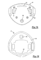
- the head 16 is mounted to a plate 92 formed at an end of segment 30E.
- Locking tabs 94 extend out from recesses 96 formed in the plate 92 and form part of a locking mechanism 98 that will be described in greater detail below.
- a centering tab 100 and a securing ridge 102 also extend out from the plate 92 and aid in the securing of the head 16 onto the plate 92.
- the head 16 has a bottom 104 essentially shaped to match the plate 92. Specifically, a centering hole 106 is formed in the bottom 100 for receiving the centering tab 100 (Figure 7A). Moreover, a contoured edge 108 is formed on the bottom 104 that is shaped to engage the securing ridge 102 ( Figure 7A).
- the locking tabs 94 are each biased by a biasing member 110, a spring in the preferred embodiment, to a locked position.
- Buttons 112 are mounted on each side of the plate 92 and engage the locking tabs 94. The buttons 112 may be pushed towards one another against the biasing force of the biasing members 110 to move the locking tabs 94 to an unlocked position.
- the bottom 104 of the head 16 includes locking tab recesses 114 sized to receive the locking tabs 94 and button recesses 116 sized to receive the buttons 112.
- buttons 112 are urged against the biasing members 110 such that the locking tabs 94 move to the unlocked position.
- the head 16 is then placed onto the plate 92 such that the centering tab 100 (Figure 7A) aligns with the centering hole 106 ( Figure 7B), the securing ridge 102 abuts the contoured edge 108, and the locking tabs 94 extend into the locking tab recesses 114.
- the buttons 112 are then released, and the locking tabs 94 move to the locked position where lips 118 formed on the locking tabs 94 engage the locking tab recess 114 and prevent removal of the head 16 from the plate 92.
- the buttons 112 must again be depressed such that the lips 118 are clear of the locking tab recesses 114, at which time the head 16 may be freely removed.
- Each leg 18A-C includes a body 120A-C having a first portion 122A-C and a second portion 124A-C. Each body 120A-C further defines an inner surface 126A-C (best seen in Figure 3) having a groove 128A-C (best seen in Figure 3) formed therein.
- the legs 18A-C are rotatingly coupled at an end of their first portions 122A-C to the cap 22 of the base 12 to form a tripod configuration.
- Rubber stoppers 130A-C are formed at an end of the second portions 124A-C opposite the first portions 122A-C to provide a gripping surface for the legs 18A-C.
- the legs 18A-C further include snap bars 132A-C that extend from the inner surface 126A-C to the base 12.
- the snap bars 132A-C have a first member 134A-C and a second member 138A-C pivotably coupled to one another.
- the first members 134A-C are each pivotably coupled to the collar 24 of the base 12 and the second members 138A-C are each pivotably coupled to the inner surfaces 126A-C of each leg 18A-C.
- a locking feature 140A-C on the snap bars 132A-C keep the first member 134A-C aligned with the second member 138A-C such that the snap bars 132A-C act as struts for the legs 18A-C and lock the legs 18A-C into their extended positions.
- the locking feature 140A-C includes a snap fit detent between the first member 134A-C and the second member 138A-C, although various other methods of locking may be employed.
- the neck 14 In order to store the tripod assembly 10, the neck 14 must be fully collapsed as illustrated in Figure 2.
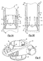
- the locking feature 140A-C is then disengaged by pulling on an end of the first member 134A-C. This releases the first and second members 134A-C, 138A-C and allows them to pivot with respect to one another. Then, as illustrated in Figure 3, the snap bars 132A-C must be moved such that the first member 134A-C no longer aligns with the second member 138A-C.
- the legs 18A-C may then be moved from the extended position to a closed position, shown in Figure 4. It should be noted legs 18A and 18C have been removed from Figure 4 for the sake of clarity.
- the legs 18A-C pivot about the cap 22 of the base 12. Simultaneously with this pivoting, the snap bars 132A-C fold such that the second members 138A-C fit within the first members 134A-C. The first members 134A-C are in turn held within the grooves 128A-C.
- the first portions 126A-C encapsulate the neck 14 and the base 12 while the second portions 128A-C encapsulate the head 16.
- the inner surfaces 126A-C of the legs 18A-C are contoured to fully enclose the base 12, neck 14, and head 16 thereby providing a protective shell.
- the legs 18A-C may be held in the closed position by any conventional locking mechanism (not shown).
- This protective shell formed by the legs 18A-C in the closed position provides a compact profile for the tripod assembly 10 thereby making the tripod assembly easily transportable. Also, the legs 18A-C serve to protect the head 16 from damage during transport or storage without requiring removal and separate storage.
Landscapes
- Engineering & Computer Science (AREA)
- General Engineering & Computer Science (AREA)
- Mechanical Engineering (AREA)
- Physics & Mathematics (AREA)
- General Physics & Mathematics (AREA)
- Radar, Positioning & Navigation (AREA)
- Remote Sensing (AREA)
- Accessories Of Cameras (AREA)
Abstract
Description
Claims (18)
- A support assembly comprising:wherein said plurality of legs form a support for said head in an upright position when in said open position and said plurality of legs at least partially enclose said base and said head when in said closed position.a base;a head mounted to said base; anda plurality of legs coupled to said base and moveable between an open position and a closed position;
- The support assembly of claim 1, wherein said legs include a first portion for enclosing said head when said legs are in said closed position.
- The support assembly of claim 2, wherein said legs include a second portion for enclosing said base when said legs are in said closed position.
- The support assembly of claim 1, wherein said legs include a snap bar extending from an inner surface of the legs to the base, said snap bar having a locking feature for locking said legs in said open position.
- The support assembly of claim 4, wherein said snap bars each have a first member and a second member pivotally coupled to one another, said first member being in alignment with said second member when said legs are in said open position, and said first member being out of alignment with said second member when said legs are in said closed position.
- The support assembly of claim 4, wherein said locking feature is formed between said first member and said second member and locks said first member into alignment with said second member when said legs are in said open position.
- The support assembly of claim 4, wherein said legs include a groove formed on the inner surface, said groove receiving said snap bar when said legs are in said closed position.
- The support assembly of claim 1, further comprising a neck coupled between said head and said base, said neck extendable and collapsible to support said head at various heights.
- The support assembly of claim 8, further comprising an incremental movement system coupled to said neck, said incremental movement system for incrementally extending or collapsing a portion of said neck.
- The support assembly of claim 9, wherein said incremental movement system includes a rack formed on said neck and a collar having a pinion, said pinion in engagement with said rack to incrementally move said neck.
- The support assembly of claim 8, further comprising a plate at an end of said neck for mounting said head.
- The support assembly of claim 11, wherein said head is removable from said neck.
- The support assembly of claim 12, wherein said head is coupled to said plate via a locking mechanism.
- The support assembly of claim 13, wherein said locking mechanism includes at least one depressible tab for engaging and disengaging the locking mechanism.
- The support assembly of claim 14, wherein said plate includes a first detent and a second detent and said head includes a recess for receiving said first detent and a rib for abutting said second detent, said detents securing said head to said plate.
- The support assembly of claim 1, wherein said head includes a laser sight.
- A tripod assembly comprising:wherein said plurality of legs form a tripod to support said body portion in an upright position when in said open position and said plurality of legs enclose said body portion when in said closed position.a body portion; anda plurality of legs coupled to said body portion and moveable between an open position and a closed position;
- A tripod assembly comprising:wherein said head is coupled to said plate via a locking mechanism including at least one depressible tab for engaging and disengaging the locking mechanism.a base;a plate mounted to said base;a head removably mounted to said plate;a plurality of legs coupled to said base and movable between an extended position for supporting said base in an upright position and a retracted position;
Applications Claiming Priority (2)
| Application Number | Priority Date | Filing Date | Title |
|---|---|---|---|
| US51670403P | 2003-11-03 | 2003-11-03 | |
| US516704P | 2003-11-03 |
Publications (2)
| Publication Number | Publication Date |
|---|---|
| EP1528311A2 true EP1528311A2 (en) | 2005-05-04 |
| EP1528311A3 EP1528311A3 (en) | 2005-08-17 |
Family
ID=34421836
Family Applications (1)
| Application Number | Title | Priority Date | Filing Date |
|---|---|---|---|
| EP04025870A Withdrawn EP1528311A3 (en) | 2003-11-03 | 2004-11-01 | Tripod assembly |
Country Status (5)
| Country | Link |
|---|---|
| US (1) | US7011280B2 (en) |
| EP (1) | EP1528311A3 (en) |
| JP (1) | JP2005140327A (en) |
| AU (1) | AU2004226925A1 (en) |
| NZ (1) | NZ552870A (en) |
Cited By (4)
| Publication number | Priority date | Publication date | Assignee | Title |
|---|---|---|---|---|
| WO2006052141A1 (en) * | 2004-11-02 | 2006-05-18 | Abyssus Marine Services As | Device for placing equipment on the sea floor |
| EP1939586A3 (en) * | 2006-12-29 | 2010-12-22 | Robert Bosch Gmbh | Laser projection device |
| US8684327B2 (en) | 2008-01-16 | 2014-04-01 | Indian Industries, Inc. | Temporary support |
| DE102022102365A1 (en) | 2022-02-01 | 2023-08-03 | Bessey Tool Gmbh & Co. Kg | Stand for a support |
Families Citing this family (42)
| Publication number | Priority date | Publication date | Assignee | Title |
|---|---|---|---|---|
| TWI321678B (en) * | 2006-04-21 | 2010-03-11 | Qisda Corp | Base for display device |
| US7718878B2 (en) * | 2006-06-09 | 2010-05-18 | Randall L May | Musical instrument stand with assisted extension |
| US7438266B2 (en) * | 2006-06-09 | 2008-10-21 | Randall L May | Stackable instrument stadium hardware stand |
| KR100966742B1 (en) * | 2007-06-12 | 2010-06-29 | 삼부기술 주식회사 | Multi-stage adjustable GPS cradle |
| USD632720S1 (en) * | 2007-08-31 | 2011-02-15 | Trek Technologies, Llc | Wide splay collapsible tripod |
| US20150330558A1 (en) * | 2008-05-15 | 2015-11-19 | Air Systems, Inc. Dba Air Systems International, Inc. | Integrated portable stand, power supply, and control panel |
| US20150152998A1 (en) * | 2013-12-02 | 2015-06-04 | Air Systems, Inc. Dba Air Systems International, Inc. | Collapsible portable stand with telescoping support and integral storage case |
| USD670752S1 (en) * | 2008-09-18 | 2012-11-13 | Edward Barber | Portable camera mount |
| KR101156171B1 (en) * | 2008-10-30 | 2012-07-03 | 강필식 | Quick shoe for Camera |
| KR100917353B1 (en) * | 2009-05-06 | 2009-09-16 | 삼부기술 주식회사 | JPPS holder for easy height adjustment |
| CN101598886B (en) * | 2009-07-07 | 2010-12-29 | 刘昊 | Four-axis photography gimbal |
| US8201979B2 (en) * | 2009-11-20 | 2012-06-19 | Pelican Products, Inc. | Collapsible light |
| US9863573B2 (en) * | 2010-02-18 | 2018-01-09 | Randall May International Incorporated | Instrument and speaker lift stand |
| US9377158B2 (en) * | 2010-12-14 | 2016-06-28 | Randall May International, Inc. | Articulating amplifier stand |
| KR101403149B1 (en) | 2012-10-02 | 2014-06-03 | 윤영휘 | Foldable tripod |
| US9243787B2 (en) | 2012-10-28 | 2016-01-26 | Measurement Ltd. | Automotive safety device |
| WO2014066839A1 (en) * | 2012-10-28 | 2014-05-01 | Measurement Ltd. | Automotive safety device |
| US9114752B2 (en) | 2012-10-28 | 2015-08-25 | Measurement Ltd. | Automotive safety device |
| CN104500841B (en) * | 2013-12-04 | 2017-02-08 | 陈蓝天 | Water pipe redirection rod |
| USD741397S1 (en) | 2014-10-17 | 2015-10-20 | Kenu, Inc. | Tripod for an electronic device |
| USD751624S1 (en) | 2014-10-17 | 2016-03-15 | Kenu, Inc. | Ball head of a tripod for an electronic device |
| US9298066B1 (en) * | 2014-10-28 | 2016-03-29 | Eagle Fan | Multi-functional support assembly |
| EP3254016B1 (en) | 2015-02-04 | 2019-10-02 | Milwaukee Electric Tool Corporation | Light |
| US9651850B2 (en) | 2015-04-20 | 2017-05-16 | Intellectual Fortress, LLC | Image processing system and method for object tracking |
| US9243741B1 (en) | 2015-04-20 | 2016-01-26 | Intellectual Fortress, LLC | Telescoping monopod apparatus for holding photographic instrument |
| US10378739B2 (en) | 2015-04-24 | 2019-08-13 | Milwaukee Electric Tool Corporation | Stand light |
| US10775032B2 (en) | 2015-07-01 | 2020-09-15 | Milwaukee Electric Tool Corporation | Area light |
| US10323831B2 (en) | 2015-11-13 | 2019-06-18 | Milwaukee Electric Tool Corporation | Utility mount light |
| USD816252S1 (en) | 2016-05-16 | 2018-04-24 | Milwaukee Electric Tool Corporation | Light |
| USD796571S1 (en) | 2016-06-16 | 2017-09-05 | Kenu, Inc. | Ball head of a portable stand for an electronic device |
| USD822092S1 (en) * | 2017-03-07 | 2018-07-03 | Gopro, Inc. | Telescoping tripod camera mount |
| CN215892050U (en) * | 2017-10-06 | 2022-02-22 | 米沃奇电动工具公司 | Floor lamp |
| US11262020B2 (en) | 2018-08-02 | 2022-03-01 | Milwaukee Electric Tool Corporation | Standing tool with telescopic arm having a guide rod |
| EP4127604B1 (en) | 2020-04-03 | 2025-11-12 | Milwaukee Electric Tool Corporation | Stand for laser projection tool |
| CN113864598B (en) * | 2021-09-27 | 2023-04-11 | 刘晓丹 | Auxiliary support of photoelectric distance measuring instrument for measuring distance |
| USD1034767S1 (en) | 2021-11-15 | 2024-07-09 | Gopro, Inc. | Camera mount |
| CA3197839A1 (en) | 2022-04-28 | 2023-10-28 | Techtronic Cordless Gp | Tripod light |
| CN115289359A (en) * | 2022-08-12 | 2022-11-04 | 深圳市艾米多技术有限公司 | Adjusting structure and shooting device support |
| US12543877B2 (en) * | 2022-08-22 | 2026-02-10 | Wobig Llc | Portable equipment stand |
| USD1085204S1 (en) | 2023-08-10 | 2025-07-22 | Gopro, Inc. | Camera mount adapter |
| US20250361971A1 (en) * | 2024-05-21 | 2025-11-27 | Alan Joonatan Rebane | Portable and Height-Adjustable Monitor Stand with Universal Magnetic Attachment Mechanism |
| CN118602252B (en) * | 2024-06-28 | 2024-12-13 | 山东管通装备科技有限公司 | Azimuth positioning mapping device for water conservancy exploration |
Family Cites Families (50)
| Publication number | Priority date | Publication date | Assignee | Title |
|---|---|---|---|---|
| US1637836A (en) * | 1922-06-24 | 1927-08-02 | Cord connecter | |
| US1573496A (en) * | 1925-04-11 | 1926-02-16 | Ansco Photoproducts Inc | Tripod |
| FR668214A (en) | 1928-12-29 | 1929-10-29 | Photographer tripod | |
| US2195391A (en) * | 1937-05-21 | 1940-03-26 | Hunter Beatrice | Portable beach stand |
| DE1169146B (en) | 1958-01-17 | 1964-04-30 | Siegfried Schiansky | Device for setting the angle of spread of tripod legs, especially for photo and cinema tripods |
| US2966107A (en) * | 1958-04-14 | 1960-12-27 | Graflex Inc | Photographic camera and adapter for mounting same |
| DE1773637C3 (en) | 1968-06-15 | 1978-06-15 | Johannes 2000 Hamburg Mueller | Collapsible stands, in particular for musical instruments |
| DE2036050A1 (en) | 1970-07-21 | 1972-01-27 | Bauermann & Soehne W | tripod |
| US3771876A (en) * | 1971-11-17 | 1973-11-13 | E Ljungdahl | Producing a plane or conical optical reference surface |
| US3722847A (en) * | 1972-03-01 | 1973-03-27 | Connor C O | Instrument support structure |
| DE2231964C2 (en) | 1972-06-30 | 1984-01-12 | Ischebeck, Döpp & Co, 5828 Ennepetal | Constructional telescopic support strut - has circlip on inner tube expanded by ramp face leading to collar |
| DE2635370B2 (en) * | 1976-08-06 | 1978-11-23 | Balda-Werke Photographische Geraete Und Kunststoff Gmbh & Co Kg, 4980 Buende | Connection for mounting flash units on photographic cameras |
| NO140922C (en) * | 1976-09-03 | 1979-12-12 | Nor Mar A S | TELESCOPIC ARM. |
| DE7636864U1 (en) | 1976-11-24 | 1977-03-03 | Huennebeck Gmbh, 4030 Ratingen | HEIGHT ADJUSTABLE SUPPORT |
| DE2757340A1 (en) | 1977-12-22 | 1979-07-05 | Paul Lambert | Adjusting mechanism for market stall awnings - has telescopic support and crank rotated gear wheel engaged with rack in inside tube |
| US4208703A (en) * | 1978-02-22 | 1980-06-17 | Orr Allie E | Device holder |
| CH625867A5 (en) | 1978-10-24 | 1981-10-15 | Gefitec Sa | |
| DE7833428U1 (en) | 1978-11-10 | 1980-04-24 | Rudolf Wittner Gmbh U. Co, 7972 Isny | FLOOR TRIPOD |
| US4324477A (en) * | 1980-11-18 | 1982-04-13 | Kabushiki Kaisha L.P.L | Photographic tripod apparatus |
| US4525052A (en) * | 1983-01-27 | 1985-06-25 | Slik Tripod Co., Ltd. | Device for fixing a camera to a tripod |
| US4578870A (en) * | 1985-02-14 | 1986-04-01 | C R Laser Corporation | Selectible beam/plane projecting laser and alignment system |
| US4637836A (en) * | 1985-09-23 | 1987-01-20 | Rca Corporation | Profile control of boron implant |
| US4691444A (en) * | 1986-04-01 | 1987-09-08 | Grover Capps | Surveyor's level with constant instrument height and method |
| US4886230A (en) * | 1986-11-03 | 1989-12-12 | Cineonix, Inc. | Camera and other instrument support stand |
| FR2629564A1 (en) * | 1988-04-01 | 1989-10-06 | Gv Sa | Mounting plates for temporarily fixing an appliance to a support |
| US4852265A (en) * | 1988-04-08 | 1989-08-01 | Spectra-Physics, Inc. | Level/plumb indicator with tilt compensation |
| US5070620A (en) * | 1990-03-01 | 1991-12-10 | Crain Stephen B | Extensible and retractable rod |
| US5222708A (en) * | 1990-06-12 | 1993-06-29 | Mclellan Francis | Tripod safety collar |
| IL98944A0 (en) * | 1991-07-24 | 1992-07-15 | Hammer Mordechai | Device which widens and narrows for multiplying and transferring movement in space |
| US5137236A (en) * | 1991-08-06 | 1992-08-11 | Burns James E | Tripod |
| DE69123157T2 (en) * | 1991-08-19 | 1997-03-13 | Kenneth Stanley Brett | TRIPOD TRIPOD |
| US5144487A (en) * | 1991-09-03 | 1992-09-01 | Pacific Laser | Portable laser device for alignment tasks |
| US5590891A (en) * | 1993-05-26 | 1997-01-07 | Remin Laboratories, Inc. | Cart and luggage handle assembly with rotatable release member |
| US5552886A (en) * | 1994-03-01 | 1996-09-03 | Nikon Corporation | Laser beam transmitting apparatus |
| FR2720138B1 (en) | 1994-05-17 | 1996-07-05 | Thomson Broadcast | Camera mounting device on a tripod. |
| DE19527829A1 (en) | 1995-07-29 | 1997-01-30 | Hannes Weigel | Angle measurement method for surveying - using time for laser radiation source to throw visible beam on surface, beam passing through adjustable shutter opening and sighting level region to be measured |
| US5560573A (en) * | 1995-09-07 | 1996-10-01 | Self-Realization Fellowship Church | Portable detachable meditation armrest support |
| DE19636413C1 (en) | 1996-09-07 | 1997-09-25 | Wolfgang Fleischer | Leg-angle adjustment for wooden tripod stand |
| DE19730928C2 (en) | 1997-07-18 | 1999-09-16 | Werner Buerklin | Holding device |
| US5954531A (en) * | 1997-10-01 | 1999-09-21 | Ericsson Inc. | Releasable locking mechanism |
| US5914778A (en) * | 1998-06-01 | 1999-06-22 | Dong; Dawei | Automatic laser level |
| US6234690B1 (en) * | 1998-08-20 | 2001-05-22 | Frank Lemieux | Camera quick-release device |
| DE29914297U1 (en) | 1999-08-14 | 1999-12-09 | Mayer & Wonisch GmbH & Co. KG, 59757 Arnsberg | Laser beam leveling device |
| DE19952390A1 (en) | 1999-10-29 | 2001-05-03 | Hilti Ag | Rotational construction laser |
| DE10026559B4 (en) | 2000-05-27 | 2004-10-14 | Daimlerchrysler Ag | Fastening arrangement for releasably securing a cover to an opening frame |
| DE10031131A1 (en) | 2000-06-30 | 2002-01-10 | Bosch Gmbh Robert | Leveling plate for construction laser, has turntable through which construction laser connected with the second carrier unit is turnable to the level of the second carrier unit |
| DE10065247A1 (en) | 2000-12-29 | 2002-07-04 | Lion Rock Trading Far East Ltd | Telescopic leg for small item of furniture comprises outer, metallic tube with guide bush mounted in its top end, in which inner tube slides, outer tube having peripheral groove into which collar on bush fits |
| DE10065250A1 (en) | 2000-12-29 | 2002-07-04 | Lion Rock Trading Far East Ltd | Telescopic leg for small item of furniture comprises outer and inner metal tube, inner tube having cap on its lower end with flexible vanes which slide along inner surface of outer tube |
| CN100416153C (en) * | 2002-03-28 | 2008-09-03 | 林诺曼弗罗托股份有限公司 | Tripod for supporting optical or photographic equipment |
| US6789772B2 (en) * | 2003-01-14 | 2004-09-14 | Ultimate Support Systems, Inc. | Off-axis reducible support structure |
-
2004
- 2004-11-01 EP EP04025870A patent/EP1528311A3/en not_active Withdrawn
- 2004-11-01 AU AU2004226925A patent/AU2004226925A1/en not_active Abandoned
- 2004-11-01 NZ NZ552870A patent/NZ552870A/en unknown
- 2004-11-02 JP JP2004319555A patent/JP2005140327A/en active Pending
- 2004-11-02 US US10/979,953 patent/US7011280B2/en not_active Expired - Fee Related
Cited By (7)
| Publication number | Priority date | Publication date | Assignee | Title |
|---|---|---|---|---|
| WO2006052141A1 (en) * | 2004-11-02 | 2006-05-18 | Abyssus Marine Services As | Device for placing equipment on the sea floor |
| EP1939586A3 (en) * | 2006-12-29 | 2010-12-22 | Robert Bosch Gmbh | Laser projection device |
| US8684327B2 (en) | 2008-01-16 | 2014-04-01 | Indian Industries, Inc. | Temporary support |
| US9050513B2 (en) | 2008-01-16 | 2015-06-09 | Indian Industries, Inc. | Temporary support |
| US10082239B2 (en) | 2008-01-16 | 2018-09-25 | Indian Industries, Inc. | Temporary support |
| DE102022102365A1 (en) | 2022-02-01 | 2023-08-03 | Bessey Tool Gmbh & Co. Kg | Stand for a support |
| WO2023148002A1 (en) | 2022-02-01 | 2023-08-10 | Bessey Tool Gmbh & Co. Kg | Holding stand for a support |
Also Published As
| Publication number | Publication date |
|---|---|
| US20050092878A1 (en) | 2005-05-05 |
| EP1528311A3 (en) | 2005-08-17 |
| NZ552870A (en) | 2007-08-31 |
| AU2004226925A1 (en) | 2005-05-19 |
| US7011280B2 (en) | 2006-03-14 |
| JP2005140327A (en) | 2005-06-02 |
Similar Documents
| Publication | Publication Date | Title |
|---|---|---|
| EP1528311A2 (en) | Tripod assembly | |
| EP1445530B1 (en) | Tripod arrangement | |
| US10982806B2 (en) | Close-pack, high-aspect-ratio camera tripod | |
| US8047481B2 (en) | Continuously angle-adjustable multifunction tripod | |
| US8708102B2 (en) | Vehicle utility ladder | |
| CA2296854C (en) | Lockable stand | |
| US8029197B2 (en) | Hand-held image stabilization and balancing system for cameras | |
| US6371495B2 (en) | Trolley with fold-out legs | |
| US20090090864A1 (en) | Thermal imager having integrated support assembly | |
| US8733712B2 (en) | Extendable, telescoping monopod | |
| US8118439B2 (en) | Repositionable lens cover | |
| US20070221797A1 (en) | Worklight Stand With Worklight Coupling Means | |
| US10527220B2 (en) | Pneumatic foot-operated monopod | |
| US20050213959A1 (en) | Adjustable optical apparatus adapter | |
| WO1992020953A1 (en) | Vertically adjustable mounting post for optical element | |
| US10996017B2 (en) | Quickly deployable tripod | |
| US4377269A (en) | Stand for optical devices, particularly cameras | |
| KR102155733B1 (en) | Anti-rotation structure, tube structure and photographing support | |
| JP2021529994A (en) | Switchable tripod for video / photographic equipment | |
| JP3581957B2 (en) | Workbench | |
| KR102089862B1 (en) | Camera supporter including horizontal centering control assembled with lighting equipment | |
| US20070223239A1 (en) | Method And Apparatus For Coupling A Worklight To A Stand | |
| EP1868380B1 (en) | Projector | |
| US20070223234A1 (en) | Worklight Power Cord and Power Cord Storage Means | |
| US9052060B1 (en) | Tripod with storage structure |
Legal Events
| Date | Code | Title | Description |
|---|---|---|---|
| PUAI | Public reference made under article 153(3) epc to a published international application that has entered the european phase |
Free format text: ORIGINAL CODE: 0009012 |
|
| AK | Designated contracting states |
Kind code of ref document: A2 Designated state(s): AT BE BG CH CY CZ DE DK EE ES FI FR GB GR HU IE IS IT LI LU MC NL PL PT RO SE SI SK TR |
|
| AX | Request for extension of the european patent |
Extension state: AL HR LT LV MK YU |
|
| PUAL | Search report despatched |
Free format text: ORIGINAL CODE: 0009013 |
|
| AK | Designated contracting states |
Kind code of ref document: A3 Designated state(s): AT BE BG CH CY CZ DE DK EE ES FI FR GB GR HU IE IS IT LI LU MC NL PL PT RO SE SI SK TR |
|
| AX | Request for extension of the european patent |
Extension state: AL HR LT LV MK YU |
|
| RIC1 | Information provided on ipc code assigned before grant |
Ipc: 7F 16M 11/18 B Ipc: 7F 16M 11/04 B Ipc: 7F 16M 11/20 A |
|
| 17P | Request for examination filed |
Effective date: 20051216 |
|
| AKX | Designation fees paid |
Designated state(s): AT BE BG CH CY CZ DE DK EE ES FI FR GB GR HU IE IS IT LI LU MC NL PL PT RO SE SI SK TR |
|
| 17Q | First examination report despatched |
Effective date: 20060727 |
|
| STAA | Information on the status of an ep patent application or granted ep patent |
Free format text: STATUS: THE APPLICATION IS DEEMED TO BE WITHDRAWN |
|
| 18D | Application deemed to be withdrawn |
Effective date: 20100601 |