CN215892050U - Floor lamp - Google Patents
Floor lamp Download PDFInfo
- Publication number
- CN215892050U CN215892050U CN202120008264.7U CN202120008264U CN215892050U CN 215892050 U CN215892050 U CN 215892050U CN 202120008264 U CN202120008264 U CN 202120008264U CN 215892050 U CN215892050 U CN 215892050U
- Authority
- CN
- China
- Prior art keywords
- light
- head
- lamp
- support arm
- head assembly
- Prior art date
- Legal status (The legal status is an assumption and is not a legal conclusion. Google has not performed a legal analysis and makes no representation as to the accuracy of the status listed.)
- Active
Links
Images


Classifications
-
- F—MECHANICAL ENGINEERING; LIGHTING; HEATING; WEAPONS; BLASTING
- F21—LIGHTING
- F21L—LIGHTING DEVICES OR SYSTEMS THEREOF, BEING PORTABLE OR SPECIALLY ADAPTED FOR TRANSPORTATION
- F21L4/00—Electric lighting devices with self-contained electric batteries or cells
- F21L4/04—Electric lighting devices with self-contained electric batteries or cells characterised by the provision of a light source housing portion adjustably fixed to the remainder of the device
-
- F—MECHANICAL ENGINEERING; LIGHTING; HEATING; WEAPONS; BLASTING
- F21—LIGHTING
- F21S—NON-PORTABLE LIGHTING DEVICES; SYSTEMS THEREOF; VEHICLE LIGHTING DEVICES SPECIALLY ADAPTED FOR VEHICLE EXTERIORS
- F21S6/00—Lighting devices intended to be free-standing
- F21S6/005—Lighting devices intended to be free-standing with a lamp housing maintained at a distance from the floor or ground via a support, e.g. standing lamp for ambient lighting
- F21S6/006—Lighting devices intended to be free-standing with a lamp housing maintained at a distance from the floor or ground via a support, e.g. standing lamp for ambient lighting for direct lighting only, e.g. task lighting
-
- F—MECHANICAL ENGINEERING; LIGHTING; HEATING; WEAPONS; BLASTING
- F21—LIGHTING
- F21S—NON-PORTABLE LIGHTING DEVICES; SYSTEMS THEREOF; VEHICLE LIGHTING DEVICES SPECIALLY ADAPTED FOR VEHICLE EXTERIORS
- F21S9/00—Lighting devices with a built-in power supply; Systems employing lighting devices with a built-in power supply
- F21S9/02—Lighting devices with a built-in power supply; Systems employing lighting devices with a built-in power supply the power supply being a battery or accumulator
-
- F—MECHANICAL ENGINEERING; LIGHTING; HEATING; WEAPONS; BLASTING
- F21—LIGHTING
- F21V—FUNCTIONAL FEATURES OR DETAILS OF LIGHTING DEVICES OR SYSTEMS THEREOF; STRUCTURAL COMBINATIONS OF LIGHTING DEVICES WITH OTHER ARTICLES, NOT OTHERWISE PROVIDED FOR
- F21V11/00—Screens not covered by groups F21V1/00, F21V3/00, F21V7/00 or F21V9/00
- F21V11/16—Screens not covered by groups F21V1/00, F21V3/00, F21V7/00 or F21V9/00 using sheets without apertures, e.g. fixed
-
- F—MECHANICAL ENGINEERING; LIGHTING; HEATING; WEAPONS; BLASTING
- F21—LIGHTING
- F21V—FUNCTIONAL FEATURES OR DETAILS OF LIGHTING DEVICES OR SYSTEMS THEREOF; STRUCTURAL COMBINATIONS OF LIGHTING DEVICES WITH OTHER ARTICLES, NOT OTHERWISE PROVIDED FOR
- F21V21/00—Supporting, suspending, or attaching arrangements for lighting devices; Hand grips
- F21V21/14—Adjustable mountings
- F21V21/22—Adjustable mountings telescopic
-
- F—MECHANICAL ENGINEERING; LIGHTING; HEATING; WEAPONS; BLASTING
- F21—LIGHTING
- F21V—FUNCTIONAL FEATURES OR DETAILS OF LIGHTING DEVICES OR SYSTEMS THEREOF; STRUCTURAL COMBINATIONS OF LIGHTING DEVICES WITH OTHER ARTICLES, NOT OTHERWISE PROVIDED FOR
- F21V21/00—Supporting, suspending, or attaching arrangements for lighting devices; Hand grips
- F21V21/14—Adjustable mountings
- F21V21/26—Pivoted arms
-
- F—MECHANICAL ENGINEERING; LIGHTING; HEATING; WEAPONS; BLASTING
- F21—LIGHTING
- F21V—FUNCTIONAL FEATURES OR DETAILS OF LIGHTING DEVICES OR SYSTEMS THEREOF; STRUCTURAL COMBINATIONS OF LIGHTING DEVICES WITH OTHER ARTICLES, NOT OTHERWISE PROVIDED FOR
- F21V21/00—Supporting, suspending, or attaching arrangements for lighting devices; Hand grips
- F21V21/40—Hand grips
-
- F—MECHANICAL ENGINEERING; LIGHTING; HEATING; WEAPONS; BLASTING
- F21—LIGHTING
- F21V—FUNCTIONAL FEATURES OR DETAILS OF LIGHTING DEVICES OR SYSTEMS THEREOF; STRUCTURAL COMBINATIONS OF LIGHTING DEVICES WITH OTHER ARTICLES, NOT OTHERWISE PROVIDED FOR
- F21V23/00—Arrangement of electric circuit elements in or on lighting devices
- F21V23/06—Arrangement of electric circuit elements in or on lighting devices the elements being coupling devices, e.g. connectors
-
- F—MECHANICAL ENGINEERING; LIGHTING; HEATING; WEAPONS; BLASTING
- F21—LIGHTING
- F21V—FUNCTIONAL FEATURES OR DETAILS OF LIGHTING DEVICES OR SYSTEMS THEREOF; STRUCTURAL COMBINATIONS OF LIGHTING DEVICES WITH OTHER ARTICLES, NOT OTHERWISE PROVIDED FOR
- F21V21/00—Supporting, suspending, or attaching arrangements for lighting devices; Hand grips
- F21V21/14—Adjustable mountings
- F21V21/30—Pivoted housings or frames
-
- F—MECHANICAL ENGINEERING; LIGHTING; HEATING; WEAPONS; BLASTING
- F21—LIGHTING
- F21W—INDEXING SCHEME ASSOCIATED WITH SUBCLASSES F21K, F21L, F21S and F21V, RELATING TO USES OR APPLICATIONS OF LIGHTING DEVICES OR SYSTEMS
- F21W2131/00—Use or application of lighting devices or systems not provided for in codes F21W2102/00-F21W2121/00
- F21W2131/40—Lighting for industrial, commercial, recreational or military use
- F21W2131/402—Lighting for industrial, commercial, recreational or military use for working places
-
- F—MECHANICAL ENGINEERING; LIGHTING; HEATING; WEAPONS; BLASTING
- F21—LIGHTING
- F21Y—INDEXING SCHEME ASSOCIATED WITH SUBCLASSES F21K, F21L, F21S and F21V, RELATING TO THE FORM OR THE KIND OF THE LIGHT SOURCES OR OF THE COLOUR OF THE LIGHT EMITTED
- F21Y2105/00—Planar light sources
- F21Y2105/10—Planar light sources comprising a two-dimensional array of point-like light-generating elements
- F21Y2105/14—Planar light sources comprising a two-dimensional array of point-like light-generating elements characterised by the overall shape of the two-dimensional array
- F21Y2105/16—Planar light sources comprising a two-dimensional array of point-like light-generating elements characterised by the overall shape of the two-dimensional array square or rectangular, e.g. for light panels
-
- F—MECHANICAL ENGINEERING; LIGHTING; HEATING; WEAPONS; BLASTING
- F21—LIGHTING
- F21Y—INDEXING SCHEME ASSOCIATED WITH SUBCLASSES F21K, F21L, F21S and F21V, RELATING TO THE FORM OR THE KIND OF THE LIGHT SOURCES OR OF THE COLOUR OF THE LIGHT EMITTED
- F21Y2115/00—Light-generating elements of semiconductor light sources
- F21Y2115/10—Light-emitting diodes [LED]
Abstract
A floor lamp includes a telescoping body having a main central axis, an extension pole extendable from the main central axis, and a sleeve movably supported on the main central axis. The head assembly is supported by the extension rod and includes a light source. The plurality of legs are pivotally coupled to the telescoping body and are movable with the sleeve from a collapsed position to an extended position in which the distal ends of the plurality of legs are moved away from the telescoping body. The lamp housing is coupled to an end of the main central shaft and is configured to receive the head assembly when the extension rod is retracted into the main central shaft. The light head is rotatable 180 degrees relative to the support arm, and when the head assembly is received in the light shade, the head assembly can be rotated to a position where the light source is directed toward the telescoping body.
Description
The application is divisional application of patent applications with application number of 201890001406.3, application date of 2018, 10 and 5 months and name of' floor lamp
Technical Field
The present invention relates to work lights and, more particularly, to work lights, i.e., floor lights, that include a foldable stand.
Background
Floor lamps may be used to provide illumination to work areas that are difficult to illuminate. These work areas include, for example, workplaces, ceiling spaces, basement areas, and the like.
SUMMERY OF THE UTILITY MODEL
In a first aspect, the present invention provides a floor lamp including a telescoping body including a primary central shaft, an extension pole defining a central longitudinal axis and extendable from the primary central shaft, and a sleeve movably supported on the primary central shaft. A head assembly supported by the extension pole, the head assembly including a lamp head, a support arm coupled to opposing sides of the lamp head, and a light source coupled to the lamp head. A plurality of legs pivotally coupled to the telescoping body, the plurality of legs movable with the sleeve from a collapsed position to an extended position, wherein in the extended position, distal ends of the plurality of legs move away from the telescoping body. And a light housing coupled to an end of the primary central shaft, the light housing configured to receive the head assembly when the extension rod is retracted into the primary central shaft. The light head is rotatable relative to the support arm about a first axis perpendicular to the central longitudinal axis, wherein the light head is rotatable 180 degrees relative to the support arm, and wherein the head assembly is rotatable to a position where the light source is directed towards the telescoping body when the head assembly is received in the light shade.
Optionally, the lamp head comprises a boss coupled to the support arm and positioned coaxially with the first axis, wherein the lamp head is rotatable about the boss.
Optionally, the floor lamp further comprises a washer located between the boss and the support arm, wherein the washer holds the lamp head in any rotational position relative to the support arm.
Optionally, the support arm is rotatable relative to the extension bar about the central longitudinal axis.
Optionally, the support arm surrounds and supports the lighthead and forms a generally U-shaped cradle.
In a second aspect, the present invention provides a floor lamp that includes a telescoping body that includes a primary central shaft, an extension pole extendable from the primary central shaft, and a sleeve movably supported on the primary central shaft. A head assembly supported by the extension pole, the head assembly including a support arm, a light head rotatably coupled to the support arm, a light source supported by the light head, and a lens supported by the light head. A plurality of legs pivotally coupled to the telescoping body, the plurality of legs movable with the sleeve from a collapsed position to an extended position in which distal ends of the plurality of legs move away from the telescoping body. And a light housing coupled to an end of the primary central shaft, the light housing configured to receive the head assembly when the extension rod is retracted into the primary central shaft. Wherein the light source and the lens face the telescoping body when the head assembly is received in the lamp housing.
Optionally, the light head is movable between a first position in which the light head is positioned on top of the light housing and a second position in which the light head is received within the light housing.
Optionally, the lighthead is rotatable relative to the support arm about a first axis, and wherein the support arm is rotatable relative to the extension bar about a second axis perpendicular to the first axis.
Optionally, the canopy prevents rotation of the head assembly about the first axis and the second axis when the head assembly is received within the canopy.
Optionally, the light head comprises a boss coupled to the support arm and a washer located between the boss and the support arm, and wherein the washer holds the light head in any rotational position relative to the support arm.
Optionally, the light cover includes cutouts formed in opposing sides of the light cover, and wherein the cutouts receive the support arms when the extension bar is retracted into the primary central axis.
Optionally, the light shade includes a plurality of notches formed on an inner surface of the light shade between the cutouts, and wherein the plurality of notches receive portions of the support arm when the head assembly is in a lowermost rest position in which the light head rests on top of the light shade.
Optionally, the canopy includes a detent mechanism to releasably retain the support arm when the extension rod is retracted into the main central shaft.
Optionally, the lamp housing and the head assembly are bonded to each other.
In a third aspect, the present invention provides a floor lamp that includes a telescoping body that includes a primary central shaft, an extension pole extendable from the primary central shaft, and a sleeve movably supported on the primary central shaft. A head assembly supported by the extension rod, the head assembly including a support arm, a light head coupled to the support arm, and a light source coupled to the light head. A plurality of legs pivotally coupled to the telescoping body, the plurality of legs movable with the sleeve from a collapsed position to an extended position in which distal ends of the plurality of legs move away from the telescoping body. And a canopy coupled to an end of the main central shaft, the canopy configured to receive the head assembly when the extension rod is retracted into the main central shaft, and wherein the canopy includes a detent mechanism having a detent arm that engages the support arm when the head assembly is received in the canopy.
Optionally, the head assembly is movable between a first position in which the lighthead is positioned on top of the light housing and a second position in which the lighthead is received within the light housing.
Optionally, the light cover includes cutouts formed in opposing sides of the light cover, and wherein the cutouts receive the support arms when the extension bar is retracted into the primary central axis.
Optionally, the light shade includes a plurality of notches formed on an inner surface of the light shade between the cutouts, and wherein the plurality of notches receive portions of the support arm when the head assembly is in the first position.
Optionally, the lamp housing is coupled to the main central shaft at a fixed distance.
Other aspects of the utility model will become apparent by consideration of the detailed description and accompanying drawings.
Drawings
Fig. 1A is a side view of a floor lamp in a collapsed position, the floor lamp including a leg and a head assembly.
Fig. 1B is a side view of the floor lamp with the legs in an extended position.
Fig. 1C is a side view of the floor lamp with the legs in an extended position and the head assembly in an extended position.
Fig. 2A is a side view of the floor lamp of fig. 1A-1C in a folded position.
Fig. 2B is a side view of the floor lamp of fig. 1A-1C in a folded position.
Fig. 2C is a side view of the floor lamp of fig. 1A-1C in a folded position.
Fig. 2D is a side view of the floor lamp of fig. 1A-1C in a folded position.
Fig. 3 is a side view of the floor lamp of fig. 1A-1C in an extended position.
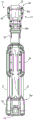
Fig. 4 is a cross-sectional view of the floor lamp in a folded position.
Fig. 5 is a cross-sectional view of a portion of the floor lamp.
Fig. 6 is a side view of the cover and head assembly of the floor lamp.
Fig. 7 is an enlarged view of the main housing of the floor lamp, showing the power outlet port.
Fig. 8 is a perspective view of the lower portion of the floor lamp showing the legs in an extended position and extension wires connected to the power port.
Fig. 9 is a side view of the lower portion of the floor lamp showing the battery pack attached to the main housing.
Fig. 10 is a perspective view of the lower portion of the floor lamp showing the battery pack removed from the main housing.
Fig. 11 is a perspective view of the lower portion of the floor lamp showing the legs forming the handle.
Fig. 12A is a front view of a head assembly of the floor lamp.
Fig. 12B is a rear view of the head assembly of the floor lamp.
Fig. 12C is a side view of the head assembly of the floor lamp.
Fig. 13 is a top perspective view of the head assembly and hood of the floor lamp.
Fig. 14 is a side view of the head assembly and hood of the floor lamp with the head assembly in a lowest rest position.
FIG. 15 is a cross-sectional view of the head assembly and the hood.
Figure 16 is an exploded view of the extension pole and main center shaft of the floor lamp.
Fig. 17 is a front perspective view of one of the legs of the floor lamp.
Fig. 18 is a rear perspective view of one of the legs of the floor lamp.
FIG. 19 is a top perspective view of the cap and head assembly with the lamp head removed.
FIG. 20 is a cross-sectional view of the cap and head assembly with the lamp head removed.
Detailed Description
Before any embodiments of the utility model are explained in detail, it is to be understood that the utility model is not limited in its application to the details of construction and the arrangement of components set forth in the following description or illustrated in the following drawings. The utility model is capable of other embodiments and of being practiced or of being carried out in various ways.
Fig. 1A to 3 illustrate a floor lamp 10 according to one embodiment of the present invention. The floor lamp 10 shown includes a main body 14, a main housing 18, legs 22, and a head assembly 26. The floor lamp 10 is movable between a collapsed position (fig. 1A and 2A-2D) and a plurality of extended positions (fig. 1B, 1C, and 3). When in the folded position, the floor lamp 10 is relatively compact for storage and transportation. When in one of the extended positions, the legs 22 of the floor lamp 10 are unfolded such that the lamp 10 is self-supporting on a surface, and the head assembly 26 may extend away from the body 14.
The illustrated body 14 is a telescoping body that includes an extension pole 30 and a main central shaft 34 that allows the body 14 to extend in length. In the illustrated embodiment, the body 14 includes two extension rods 30, the two extension rods 30 sliding into and out of the central shaft 34 and sliding relative to each other to extend the length of the body 14. In other embodiments, the body 14 may include more than two extension rods 30. As shown in fig. 1A and 1C, main body 14 extends from a first, minimum height H1 (i.e., a collapsed position, fig. 1A) to a second, maximum height H2 (i.e., an extended position, fig. 1C). When in the folded position, the first height H1 is the most compact, which is about 30 inches, and when in the extended position, the second height H2 is about 60 inches. When in the collapsed position, the extension pole 30 is disposed within the primary central axis 34. The main central shaft 34 has the same cross-sectional shape as the extension rod 30 and has a larger diameter and allows the extension rod 30 to nest therein. In the illustrated embodiment, the primary central shaft 34 and the extension rod 30 have a generally hexagonal cross-section. In other embodiments, the main central shaft 34 and the extension rod 30 may have other suitable cross-sectional shapes that prevent relative rotation between the main central shaft 34 and the extension rod 30 (e.g., square, D-shaped, oval, etc.), or the main central shaft 34 and the extension rod 30 may have a generally circular cross-section with anti-rotation features (e.g., ribs and grooves).
As shown in FIG. 16, the body 14 includes a detent mechanism to releasably secure the extension pole 30 in the maximum extended position. The illustrated brake mechanism includes a first brake member 200, a second brake member 204, a third brake member 208, and a fourth brake member 212, the first brake member 200 being coupled to an upper end of the main central shaft 34, the second brake member 204 being coupled to a lower end of the middle extension rod 30, the third brake member 208 being coupled to an upper end of the middle extension rod 30, and the fourth brake member 212 being coupled to a lower end of the inner extension rod 30. Depending on the number of extension rods 30, the braking mechanism may include fewer or more braking members. The first brake member 200 is secured to the inner surface of the primary central shaft 34 and includes a finger 216 having an enlarged head. The second stop member 204 is secured to an outer surface of the intermediate extender 30 and defines a recess 220, the recess 220 being configured to receive the enlarged head of the finger 216. The third brake member 208 is secured to the inner surface of the intermediate extender 30 and includes a finger 224 having an enlarged head. The fourth brake member 212 is secured to the outer surface of the inner extension rod 30 and defines a recess 228, the recess 228 being configured to receive the enlarged head of the finger 224.
In operation, the finger 216 of the first brake member 200 contacts the second brake member 204 as the intermediate extension rod 30 slides relative to the primary central shaft 34 to move the lower end of the intermediate extension rod 30 adjacent the upper end of the primary central shaft 34. The shape of the second brake member 204 flexes the finger 216 until the finger 216 snaps into the notch 220 of the second brake member 204. In this position, the middle extender 30 is releasably secured in an extended position relative to the main central axis 34. The fingers 216 may be released from the notches 220 by applying sufficient force to collapse the middle extender 30.
Similarly, when the inner extender 30 slides relative to the middle extender 30 to move the lower end of the inner extender 30 adjacent the upper end of the middle extender 30, the finger 224 of the third brake member 208 contacts the fourth brake member 212. The shape of fourth brake member 212 flexes fingers 224 until fingers 224 snap into notches 228 of fourth brake member 212. In this position, the inner extender 30 is releasably secured in the extended position relative to the intermediate extender 30. The fingers 224 may be released from the notches 228 by applying sufficient force to collapse the inner extension rod 30. With this arrangement, the body 14 does not include a manual actuator (e.g., a cam lock) for releasing and securing the extension bar 30 for sliding movement.
The body 14 may also extend to and remain at any height (i.e., an intermediate position) between the first height (i.e., the folded position) and the second height (i.e., the maximum extended position). The extension rods 30 are held in place relative to each other and relative to the main central shaft 34 by friction. In particular, the second and fourth brake members 204, 212 are shown to include outwardly projecting surfaces 232, 236, the surfaces 232, 236 engaging the inner surfaces of the primary central shaft 34 and the intermediate extension bar 30 as the extension bar 30 is extended and collapsed. The outwardly projecting surfaces 232, 236 generate sufficient force to hold the extension pole 30 in a neutral position against the force of gravity. The first and second brake members 200, 208 may also or alternatively include inwardly projecting surfaces that engage the outer surface of the extension pole 30 to hold the extension pole in a neutral position. In other embodiments, the body 14 may include additional detent members to releasably secure the extension bar 30 in discrete intermediate positions.
Alternative mechanisms may additionally be implemented to hold the extension pole 30 in place. For example, the lever 30 may include a friction plate to prevent the lever 30 from falling due to gravity, but this may be overcome by the user with sufficient force. In further embodiments, the extension rod 30 may include a cam adjustment mechanism to selectively tension and release two or more rods 30 of the body 14 to allow for height adjustment. In some embodiments, plastic spacers may be positioned between the extension rods 30 to create friction so that the extension rods 30 will not automatically retract when the cam adjustment is opened.
In an alternative embodiment, one extension rod 30 may include an actuator (e.g., a button) and another larger diameter extension rod 30 may include a notch. When the extension rod 30 is extended to the desired length, the actuator may engage the notch, thereby locking the rod 30 in place. To collapse the rod 30, the user may depress the actuator, thereby disengaging the actuator from the notch and collapsing the light assembly 10. In yet another embodiment, the extension bar 30 may include only friction plates to maintain the position of the bar 30 in an infinitely adjustable manner.
As shown in FIG. 4, the electrical cord 32 is positioned within the extension pole 30 and extends through the extension pole 30. Electrical wires 32 connect the head assembly 26 to the main housing 18 to provide power to the head assembly 26. More specifically, the electrical wires 32 extend between the lamp head assembly 26 of the lamp 10 and the circuit board 40. In the illustrated embodiment, the wire 32 includes a coiled portion 36. The coiled portion 36 encloses a rigid guide tube 44 that extends throughout the extension pole 30 and allows the wires 32 to expand and contract during extension and folding of the floor lamp 10. For example, the coiled portion 36 of the wire 32 may be uncoiled when the light 10 is moved to one of the extended positions, and the coiled portion 36 of the wire 32 may be retracted when the light 10 is moved to the collapsed position. The rigid guide tube 44 provides support for the coiled portion 36 so that the coiled portion 36 does not bend out of alignment or kink during extension and retraction. In addition, the coiled portion 36 allows the lamp head assembly 26 to rotate without causing significant damage to the electrical wires 32.
As shown in fig. 2A to 2D and 6, the main body 14 includes a lamp housing 46 fixed to the main center shaft 34 at a fixed distance from the main housing 18. The extension pole 30 extends from a first end 46a of the lamp housing 46 and the primary central axis 34 extends from a second end 46b of the lamp housing 46. First end 46a of lamp casing 46 defines an area for supporting head assembly 26. More specifically, first end 46a of lamp casing 46 includes cutouts 48 or apertures located on opposite sides of casing 46. The cutout 48 extends through the first end 46a of the shroud 46 and is shaped to receive the arm 102 of the lamp head assembly 26 and provide clearance for the arm 102 when the lamp 10 is in the folded position. Thus, when the lamp 10 is folded, the lamp head assembly 26 is disposed within the shroud 46 and partially surrounded by the shroud 46. In an alternative embodiment, the shroud 46 may completely surround the arm 102 of the lamp head assembly 26 without providing the cutout 48. In further embodiments, first end 46a of light housing 46 may include a mechanism (e.g., latch, detent, recess, etc.) for releasably securing head assembly 26 within housing 46 when floor lamp 10 is fully collapsed. In some embodiments, the head assembly 26 and the hood 46 may be keyed to one another to position the head assembly 26 relative to the hood 46 and prevent rotation of the head assembly 26 relative to the hood 46.
As shown in fig. 2A-2D and 3, the body 14 further includes a sleeve 50. The sleeve 50 surrounds a portion of the primary central axis 34 and is movable relative to the primary central axis 34. In the illustrated embodiment, the sleeve 50 is slidable along the major central axis 34 toward and away from the lamp casing 46. The ends of the legs 22 are coupled to the sleeve 50 for movement with the sleeve 50 between the extended and folded positions. When the floor lamp 10 is moved to the extended position, the sleeve 50 is moved axially away from the lamp housing 46, thereby moving the legs 22 away from the main housing 18. When the floor lamp 10 is moved to the collapsed position, the sleeve 50 is moved axially toward the lamp housing 46, thereby moving the legs 22 toward the main housing 18.
As shown in fig. 5, the sleeve 50 includes one or more actuators 54. In the illustrated embodiment, the sleeve 50 includes two actuators 54 located on opposite sides of the sleeve 50. The actuator 54 shown is a button that is movably coupled to the sleeve 50, but may alternatively be another type of suitable actuator. The actuator 54 is pivotable relative to the sleeve 50 about a pivot axis defined by the respective pivot pin 60. The actuator 54 is operable to hold the floor lamp 10 in the collapsed position or one of the plurality of extended positions. Each actuator 54 includes a protrusion 52. The protrusion 52 is configured to engage with a hole 56 formed in the primary central shaft 34. The illustrated actuator 54 is biased to the engaged position such that the projection 52 is received in the aperture 56, but may be manually actuated (e.g., depressible) to move the projection 52 out of the aperture 56. In the illustrated embodiment, the actuator 54 is biased by a leaf spring 57. In other embodiments, the actuator 54 may be biased by other suitable springs (e.g., torsion springs, compression springs, etc.).
When the lamp 10 is in the collapsed position such that the sleeve 50 is adjacent the lamp casing 46 (fig. 1A), the protrusion 52 extends into a hole 56 formed in the primary central shaft 34 adjacent the lamp casing 46 to lock the sleeve 50 in the collapsed position. The actuator 54 may be actuated to disengage the protrusion 52 from the aperture 56, thereby allowing the sleeve 50 to slide along the primary central axis 34 away from the lamp casing 46 and move the legs 22 toward the extended position. When the lamp 10 is in the extended position such that the sleeve 50 is adjacent the main housing 18 (fig. 1B), the protrusion 52 extends into a hole 56 formed in the main central shaft 34 adjacent the main housing 18 to lock the sleeve 50 in the extended position. Actuator 54 may be actuated again to disengage projection 52 from aperture 56, thereby allowing sleeve 50 to slide along primary central axis 34 toward lamp casing 46 and move legs 22 toward the collapsed position.
In order to disengage the projection 52 from the aperture 56 and move the sleeve 50, both actuators 54 need to be actuated simultaneously. In the illustrated embodiment, the actuators 54 are positioned on diametrically opposite sides of the sleeve 50, but are designed such that a user can engage and actuate both actuators 54 simultaneously with one hand. For example, actuator 54 has a relatively large engagement area that may be depressed by a user's thumb, a user's finger, and/or a user's palm to actuate actuator 54. With this arrangement, a user may grasp sleeve 50 and actuate actuator 54 with one hand while grasping lamp housing 46 (or other suitable structure of lamp 10) with the other hand to move sleeve 50 along primary central axis 34 to extend or collapse legs 22.
As shown in fig. 6, the lamp 10 further includes a fuel gauge 58 and a power button 62. The fuel gauge 58 and power button 62 are shown supported on the lamp housing 46. In other embodiments, the fuel gauge 58 and the power button 62 may alternatively be located elsewhere on the lamp 10.
The fuel gauge 58 includes a light or Light Emitting Diode (LED)66 to display the amount of power remaining in a battery pack 70 (fig. 1A-1C) connected to the light 10. In the illustrated embodiment, the fuel gauge 58 includes four LEDs 66 to indicate four different charge levels of the battery pack 70. For example, four illuminated LEDs 66 may indicate a battery state of charge of 100%, three illuminated LEDs 66 may indicate a battery state of charge of 75%, two illuminated LEDs 66 may indicate a battery state of charge of 50%, one illuminated LED 66 may indicate a battery state of charge of 25%, and zero illuminated LEDs 66 may indicate a battery state of charge of 0%.
The power button 62 is operable to change the lamp 10 between various states (e.g., high power, low power, and off). In the illustrated embodiment, pressing the power button 62 for a predetermined extended period of time turns off the floor lamp 10 regardless of which state is being activated when the power button 62 is pressed. In further embodiments, the lamp 10 may include more or less than two additional states. For example, the lamp 10 may include a separate actuator to change the lamp between various intensity states. In a further alternative embodiment, the light 10 may include an intensity indicator to display the intensity status of the light 10.
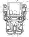
As shown in fig. 3 and 7-10, the main housing 18 is supported at the first end 14a of the main body. The main housing 18 is configured to support a battery pack 70 to supply power to the lamp 10. More specifically, the main housing 18 includes a battery receptacle 78 for receiving the battery pack 70. In the illustrated embodiment, the battery pack 70 is a rechargeable power tool battery pack, for example, a 12V lithium ion battery pack.
As shown in fig. 7 and 8, main housing 18 also includes a power port 74. The illustrated power port 74 is an input port, such as an Alternating Current (AC) power input port. For example, the power port 74 may be connected to an extension cord 76 for powering the lamp 10 via an ac power source. In some embodiments, main housing 18 may also or alternatively include a power output port. The output port allows another device (e.g., a light, a power tool, etc.) to be inserted into the light 10 to power the other device. In such embodiments, multiple devices may be daisy-chained together.
As shown in fig. 10, the main housing 18 is also shown supporting a charging circuit 80. The charging circuit 80 electrically couples the power input port 74 to the battery pack 70 to charge the battery pack 70. If the battery pack 70 and AC power source are connected to the lamp, the AC power source will charge the battery pack 70 and power the lamp 10. When the ac power source is disconnected from the lamp 10, the battery pack 70 will automatically begin powering the lamp 10 if the battery pack 70 has sufficient power.
Referring back to fig. 1A-1C, the legs 22 are pivotally coupled to the body 14 for movement between a folded position (fig. 1A) and an extended position (fig. 1B and 1C). More specifically, a first or proximal end of each leg 22 is pivotally coupled to the sleeve 50, and a second or distal end of each leg 22 is configured to contact a ground or other surface supporting the lamp 10. As the legs 22 move from the collapsed position to the extended position, the distal ends of the legs 22 move away from the body 14. In the illustrated embodiment, the floor lamp 10 includes three legs 22. In other embodiments, the floor lamp 10 may include fewer or more legs 22. In some embodiments, the legs 22 may telescope independently of one another to lengthen or shorten. For example, each leg 22 may be adjusted to a different length to support the lamp 10 when the lamp 10 is placed on an uneven surface.
As shown in fig. 8 and 10, a leg link 82 extends between each leg 22 and the body 14 to limit movement of the legs 22. In the illustrated embodiment, the leg links 82 are linear. The leg links 82 extend from the rear side of the legs 22 to a flange 84 that projects from the main housing 18. Each leg 22 includes two leg links 82 such that each leg link 82 extends from either side of a flange 84. In some embodiments, each set of two leg links 82 may be integrally formed as a U-shaped leg link.
At least one of the legs 22 includes a notch 92 or cut-out formed in the distal end of the leg 22. The notch 92 provides clearance for the extension wire 76 (fig. 8) to pass under the leg 22 and connect to the power input port 74. Specifically, at least the leg 22 aligned on the same side of the lamp 10 as the power input port 74 includes a notch 92. In the illustrated embodiment, all three legs 22 include notches 92. In other embodiments, only one or some of the legs 22 may include a notch 92.
As shown in fig. 11, each leg 22 includes a central portion 96 extending down the center of the leg 22 and two apertures 90 spaced on either side of the central portion 96. The apertures 90 extend through the legs 22 and form side portions 100 that extend away from the body 14. More specifically, the central portion 96 and the side portions 100 are angled or curved away from the main body 14 such that the aperture 90 is large enough to receive a user's hand. When in the folded position, the side portions 100 of two adjacent legs 22 are adjacent to each other to form one continuous leg handle 94. The user may slide his or her hand through one of the apertures 90 of each adjacent leg 22 and grasp the handle 94 to carry the lantern 10. Because the handle 94 is formed from two separate legs 22, a user holding the handle 94 holds the legs 22 in the folded position. In other words, two adjacent legs 22 cannot move apart from each other and toward the extended position.
In the illustrated embodiment, each leg 22 includes a main portion 96, two apertures 90, and two side portions 100. Thus, when the light 10 is in the folded position, the light 10 includes three separate handles 94, the handles 94 being formed by pairs of adjacent legs 22. The handles 94 are circumferentially spaced about the body 14. However, in an alternative embodiment, only two of the legs 22 may include the main portion 96, the aperture 90, and the two side portions 100, thus forming only one handle 94. In an alternative embodiment, the legs 22 may additionally or alternatively include a handle formed on only one of the legs 22.
Fig. 17 and 18 show one of the legs 22 in more detail. Each side portion 100 includes a gripping surface having features (e.g., ribs) configured to facilitate gripping and carrying of the lamp 10 by the handle 94. In addition, the main portion 96 includes apertures 101 that receive the ends of the respective leg links 82. Protrusions 103 are formed on the inner surface of the main portion 96 between the holes 101. The protrusion 103 helps to retain the leg link 82 within the aperture 101 when, for example, the leg 22 is in a folded position for storage or transportation. In particular, the protrusion 103 prevents the leg link 82 from bending or flexing inward and popping out of the aperture 101. In the illustrated embodiment, the protrusion 103 is integrally formed as a single piece (e.g., by molding) on the inner surface of the leg 22. In other embodiments, the protrusion 103 may be a separate component that is permanently coupled to the inner surface of the leg 22.
In an alternative embodiment, the legs 22 of the lamp 10 may be automatically deployed by a triggered release mechanism when the main housing 18 is disposed on a support surface. The user may manually adjust the height and position of the legs 22 relative to the main housing 18 by using a release mechanism or an alternative adjustment mechanism. In some embodiments, the legs 22 automatically deploy to the extended position when a user lifts the main housing 18, a handle mechanism (e.g., which is used for transporting area lights and floor lights), or a release mechanism. When the release mechanism is deployed, the legs 22 do not deploy to the locked position until the head assembly 26 is moved away from the lamp housing 46. For example, the user places the light 10 on a support surface and depresses the automatic release mechanism. The legs 22 will then be extended, and the user will have to manually slide the extension bar 30 to the desired position.
Fig. 12A-12C illustrate the head assembly 26 of the floor lamp 10. Head assembly 26 is supported on second end 14b of the body opposite main housing 18. Head assembly 26 includes a main lamp head 98, a support arm 102, a lens 106, and a light source 110. In the illustrated embodiment, the light source 110 includes a plurality of light emitting diodes 112 (LEDs) arranged in a grid. The light emitting diodes 112 are coupled to a heat sink 113 (fig. 15) located within the lamp head 98. In other embodiments, the light source 110 may include other suitable types of light sources, such as incandescent bulbs, halogen bulbs, and the like.
The lamp head 98 is semi-circular such that the portion of the lamp head 98 including the lens 106 is generally flat. In addition, the lens 106 is substantially rectangular with beveled edges. However, in alternative embodiments, the lamp head 98 and lens 106 may comprise other shapes (e.g., circular, square, etc.).
The support arm 102 is coupled to the end of the uppermost extension rod 30 opposite the lamp housing 46. The support arm 102 surrounds and supports the lighthead 98 and forms a generally U-shaped cradle. In the illustrated embodiment, the support arm 102 surrounds the bottom and sides of the lighthead 98. However, in alternative embodiments, the support arm 102 may cover more or less of the lighthead 98.
The light head 98 is rotatable relative to the support arm 102 about a first axis 114 (the first axis 114 being generally horizontal when the light 10 is supported on a surface). The first axis 114 intersects the lamp head 98 where the support arm 102 is coupled to the lamp head 98. For example, the lamp head 98 may be rotated up to 180 degrees about the first axis 114. In other embodiments, the lighthead 98 may rotate about the first axis 114 through a greater or lesser range. As shown in fig. 15, the lamp head 98 includes two bosses 116, the bosses 116 being coaxial with the first axis 114 and coupled to the support arm 102 for rotation about the two bosses 116. A gasket 117 is positioned around each boss 116 between the boss 116 and the support arm 102. Washer 117 creates friction between lamp head 98 and support arm 102 to help hold lamp head 98 in any rotational position relative to support arm 102 without the need for a positive locking engagement. In addition, the center of gravity of the lamp head 98 (and in particular the heat sink 113, the LED 112, and the lens 106) is designed to be located on the first axis 114 or near the first axis 114, thereby reducing moments about the first axis 114. In the illustrated embodiment, the gasket 117 is an O-ring. The washer 117 reduces the number of components (e.g., washers, springs, nuts, etc.) used to maintain the position of the lamp head 98 as compared to conventional lamp heads, which reduces the complexity and assembly time of the lamp 10. In other embodiments, the washer 117 may be another suitable member to create sufficient friction between the light head 98 and the support arm 102. In some embodiments, the head assembly 24 and/or the support arm 102 may include a series of detents that releasably hold the lighthead 98 in a limited number of positions.
Referring again to fig. 12A-12C, the support arm 102 is also rotatable about a second axis 118 (the second axis 118 being generally vertical when the lamp 10 is supported on a surface) relative to the uppermost extension bar 30. The second axis 118 is perpendicular to the first axis 114 and is collinear with the central longitudinal axis of the extension rod 30. In some embodiments, the light 10 may include a slip ring between the support arm 102 and the uppermost extension bar 30 to maintain an electrical connection to the light head 98 as the support arm 102 rotates relative to the extension bar 30. In such embodiments, the support arm 102 (and thus the lighthead 98) may be continuously rotated relative to the extension pole 30 by more than 360 degrees. In other embodiments, the rotation of the support arm 102 relative to the extension bar 30 may be limited to less than 360 degrees.
When in the folded position, head assembly 26 is at least partially received in lamp casing 46. In this position, the support arm 102 is received in the cutout 48 (fig. 2B and 2D) of the lamp enclosure 46. Support arms 102 and cutouts 48 ensure that head assembly 26 is properly aligned when lowered into lamp enclosure 46. When in the collapsed position, light shade 46 also prevents rotation of light head assembly 26 about either of axes 114, 118. As shown in fig. 13, the head assembly 26 also faces downward (e.g., toward the main body 14 and the main housing 18) when received in the lamp enclosure 46. That is, the lens 106 and the light source 110 face the bottom of the lamp enclosure 46 to help further protect the lens 106 and the light source 110. In alternative embodiments, more or fewer lamp head assemblies 26 may be received in lamp enclosure 46. For example, in some alternative embodiments, the lamp head assembly 26 may engage the top of the lamp casing 46, rather than being received within the lamp casing 46.
With continued reference to fig. 13, lamp casing 46 further includes notches 122 formed on the inner surface of side walls 126 of lamp casing 46 between cutouts 48. The recess 122 is shaped and sized to receive a portion of the support arm 102. In particular, as shown in fig. 14, the recess 122 receives a portion of the support arm 102 when the head assembly 26 is in the lowest rest position. In this position, the extension rod 30 is almost fully retracted into the main central shaft 34, but the lamp head 98 is not received in the lamp housing 46. Instead, the support arm 102 is rotated 90 degrees relative to the housing 46 so that the lighthead 98 rests on top of the housing 46. Recess 122 provides a keying feature that helps to retain head assembly 26 in this position and prevents rotation of head assembly 26 relative to lamp casing 46.
As shown in fig. 19 and 20, the canopy 46 also includes a detent mechanism to releasably retain the lighthead 98 in the collapsed position. The illustrated brake mechanism includes two brake arms 300 located on opposite sides of the support arm 102. Each arm 300 includes an enlarged lip 304 that engages the support arm 102 when the lighthead 98 is fully received in the light housing 46. The user may move the lighthead 98 out of the shroud 46 by lifting (e.g., pulling) the lighthead 98 with sufficient force to temporarily flex the detent arms 300 away from the support arms 102. Instead, the user may move lighthead 98 into shroud 46 by lowering (e.g., pushing) lighthead 98 with sufficient force to cause detent arms 300 to temporarily flex away from support arm 102 until support arm 102 clears enlarged lip 304 and snaps into place.
Although the utility model has been described in detail with reference to certain preferred embodiments, variations and modifications exist within the scope and spirit of one or more independent aspects of the utility model as described. Various features and advantages of the utility model are set forth in the following claims.
Claims (19)
1. A floor lamp, comprising:
a telescoping body including a main central shaft, an extension rod defining a central longitudinal axis and extendable from the main central shaft, and a sleeve movably supported on the main central shaft;
a head assembly supported by the extension pole, the head assembly including a lamp head, a support arm coupled to opposing sides of the lamp head, and a light source coupled to the lamp head;
a plurality of legs pivotally coupled to the telescoping body, the plurality of legs being movable with the sleeve from a collapsed position to an extended position, wherein in the extended position, distal ends of the plurality of legs move away from the telescoping body; and
a light housing coupled to an end of the primary central shaft, the light housing configured to receive the head assembly when the extension rod is retracted into the primary central shaft;
wherein the light head is rotatable relative to the support arm about a first axis perpendicular to the central longitudinal axis, wherein the light head is rotatable 180 degrees relative to the support arm, and wherein the head assembly is rotatable to a position where the light source is directed towards the telescoping body when the head assembly is received in the light shade.
2. A floor lamp as set forth in claim 1, wherein the lamp head includes a boss coupled to the support arm and positioned coaxially with the first axis, wherein the lamp head is rotatable about the boss.
3. A floor lamp as set forth in claim 2, further comprising a washer between the boss and the support arm, wherein the washer maintains the lamp head in any rotational position relative to the support arm.
4. A floor lamp as set forth in claim 1, wherein the support arm is rotatable relative to the extension pole about the central longitudinal axis.
5. A floor lamp as set forth in claim 1, wherein the support arm surrounds and supports the base and forms a generally U-shaped bracket.
6. A floor lamp, comprising:
a telescopic body including a main central shaft, an extension rod extendable from the main central shaft, and a sleeve movably supported on the main central shaft;
a head assembly supported by the extension pole, the head assembly including a support arm, a light head rotatably coupled to the support arm, a light source supported by the light head, and a lens supported by the light head;
a plurality of legs pivotally coupled to the telescoping body, the plurality of legs being movable with the sleeve from a collapsed position to an extended position in which distal ends of the plurality of legs are moved away from the telescoping body; and
a light housing coupled to an end of the primary central shaft, the light housing configured to receive the head assembly when the extension rod is retracted into the primary central shaft;
wherein the light source and the lens face the telescoping body when the head assembly is received in the lamp housing.
7. A floor lamp as set forth in claim 6, wherein the light head is movable between a first position in which the light head rests on top of the light housing and a second position in which the light head is received within the light housing.
8. A floor lamp as set forth in claim 6, wherein the lamp head is rotatable relative to the support arm about a first axis, and wherein the support arm is rotatable relative to the extension bar about a second axis perpendicular to the first axis.
9. A floor lamp as set forth in claim 8, wherein the canopy prevents rotation of the head assembly about the first axis and the second axis when the head assembly is received within the canopy.
10. A floor lamp as set forth in claim 6, wherein the lamp head includes a boss coupled to the support arm and a washer positioned between the boss and the support arm, and wherein the washer maintains the lamp head in any rotational position relative to the support arm.
11. A floor lamp as set forth in claim 6, wherein the light shade includes cutouts formed in opposing sides of the light shade, and wherein the cutouts receive the support arms when the extension bar is retracted into the primary central axis.
12. A floor lamp as set forth in claim 11, wherein the light shade includes a plurality of notches formed on an inner surface of the light shade between the cutouts, and wherein the plurality of notches receive portions of the support arm when the head assembly is in a lowermost rest position in which the light head rests on top of the light shade.
13. A floor lamp as set forth in claim 11, wherein the light shade includes a detent mechanism to releasably retain the support arm when the extension pole is retracted into the primary center shaft.
14. A floor lamp as set forth in claim 6, wherein the lamp cover and the head assembly are keyed to one another.
15. A floor lamp, comprising:
a telescopic body including a main central shaft, an extension rod extendable from the main central shaft, and a sleeve movably supported on the main central shaft;
a head assembly supported by the extension pole, the head assembly including a support arm, a light head coupled to the support arm, and a light source coupled to the light head;
a plurality of legs pivotally coupled to the telescoping body, the plurality of legs being movable with the sleeve from a collapsed position to an extended position in which distal ends of the plurality of legs are moved away from the telescoping body; and
a canopy coupled to an end of the primary central shaft, the canopy configured to receive the head assembly when the extension rod is retracted into the primary central shaft, and wherein the canopy includes a detent mechanism having a detent arm that engages the support arm when the head assembly is received in the canopy.
16. A floor lamp as claimed in claim 15, wherein the head assembly is movable between a first position in which the light head rests on top of the light housing and a second position in which the light head is received within the light housing.
17. A floor lamp as set forth in claim 16, wherein the light shade includes cutouts formed in opposing sides of the light shade, and wherein the cutouts receive the support arms when the extension bar is retracted into the primary central axis.
18. A floor lamp as set forth in claim 17, wherein the light shade includes a plurality of notches formed on an inner surface of the light shade between the cutouts, and wherein the plurality of notches receive portions of the support arm when the head assembly is in the first position.
19. A floor lamp as set forth in claim 15, wherein the light shade is coupled to the primary center shaft at a fixed distance.
Applications Claiming Priority (3)
| Application Number | Priority Date | Filing Date | Title |
|---|---|---|---|
| US201762569317P | 2017-10-06 | 2017-10-06 | |
| US62/569,317 | 2017-10-06 | ||
| CN201890001406.3U CN212298876U (en) | 2017-10-06 | 2018-10-05 | Floor lamp |
Related Parent Applications (1)
| Application Number | Title | Priority Date | Filing Date |
|---|---|---|---|
| CN201890001406.3U Division CN212298876U (en) | 2017-10-06 | 2018-10-05 | Floor lamp |
Publications (1)
| Publication Number | Publication Date |
|---|---|
| CN215892050U true CN215892050U (en) | 2022-02-22 |
Family
ID=65993120
Family Applications (2)
| Application Number | Title | Priority Date | Filing Date |
|---|---|---|---|
| CN202120008264.7U Active CN215892050U (en) | 2017-10-06 | 2018-10-05 | Floor lamp |
| CN201890001406.3U Active CN212298876U (en) | 2017-10-06 | 2018-10-05 | Floor lamp |
Family Applications After (1)
| Application Number | Title | Priority Date | Filing Date |
|---|---|---|---|
| CN201890001406.3U Active CN212298876U (en) | 2017-10-06 | 2018-10-05 | Floor lamp |
Country Status (4)
| Country | Link |
|---|---|
| US (5) | US10690304B2 (en) |
| EP (2) | EP3692301B1 (en) |
| CN (2) | CN215892050U (en) |
| WO (1) | WO2019071159A1 (en) |
Families Citing this family (14)
| Publication number | Priority date | Publication date | Assignee | Title |
|---|---|---|---|---|
| US10690304B2 (en) * | 2017-10-06 | 2020-06-23 | Milwaukee Electric Tool Corporation | Stand light |
| DE102019004044A1 (en) * | 2019-06-08 | 2020-12-10 | ProcServ GmbH | lamp |
| WO2021016196A1 (en) | 2019-07-19 | 2021-01-28 | Milwaukee Electric Tool Corporation | Stand light |
| USD1010203S1 (en) * | 2019-07-25 | 2024-01-02 | Milwaukee Electric Tool Corporation | Light stand |
| US11506332B2 (en) * | 2019-10-01 | 2022-11-22 | Furious Designs LLC | Mated dual support stand assembly |
| JP7323431B2 (en) * | 2019-11-07 | 2023-08-08 | 株式会社マキタ | portable light |
| USD1018956S1 (en) * | 2019-11-18 | 2024-03-19 | Milwaukee Electric Tool Corporation | Stand light |
| US20220069399A1 (en) * | 2020-08-31 | 2022-03-03 | Techtronic Cordless Gp | Tripod system |
| USD943322S1 (en) * | 2020-11-20 | 2022-02-15 | Ofala, Inc. | Guitar support |
| USD986461S1 (en) * | 2021-01-26 | 2023-05-16 | Ningbo UTEC Electric Co. Ltd. | Work light |
| EP4067727A1 (en) * | 2021-03-30 | 2022-10-05 | Nanjing Chervon Industry Co., Ltd. | Standing light |
| KR20230002152U (en) * | 2022-01-19 | 2023-11-10 | 선전 해비태트 테크놀로지 컴퍼니 리미티드 | lighting device |
| CN114738684B (en) * | 2022-03-31 | 2023-09-05 | 深圳市乐惠光电科技有限公司 | working lamp |
| CN114673970B (en) * | 2022-04-02 | 2023-01-20 | 深圳市尚为照明有限公司 | Emergency rescue lifting working lamp |
Family Cites Families (79)
| Publication number | Priority date | Publication date | Assignee | Title |
|---|---|---|---|---|
| US4324477A (en) | 1980-11-18 | 1982-04-13 | Kabushiki Kaisha L.P.L | Photographic tripod apparatus |
| US4390933A (en) * | 1980-12-11 | 1983-06-28 | I. W. Industries, Inc. | Multiple position lamp |
| DE58906599D1 (en) | 1989-09-11 | 1994-02-10 | Siemens Ag | Toggle switch with switching hysteresis. |
| US4989123A (en) | 1990-03-27 | 1991-01-29 | Best Christopher F | Collapsible light shade for a portable light |
| US5400234A (en) | 1994-03-09 | 1995-03-21 | Yu; Abraham | Light |
| US5428520A (en) | 1994-08-03 | 1995-06-27 | Skief; Mark W. | Adjustable protable utility light stand |
| US5630660A (en) | 1996-05-16 | 1997-05-20 | Chen; Wei-Fu | Warning light |
| US5934628A (en) | 1997-01-23 | 1999-08-10 | Bosnakovic; Frederick | Portable vertical support |
| US5964524A (en) | 1998-01-22 | 1999-10-12 | Regent Lighting Corporation | Worklight with stand |
| US6213626B1 (en) | 1998-06-05 | 2001-04-10 | Regent Lighting Corporation | Convertible worklight |
| DE29811569U1 (en) | 1998-06-29 | 1998-10-08 | Liu Chen An | Multi-purpose lamp |
| EP0997684B1 (en) * | 1998-10-29 | 2005-03-30 | Arnold & Richter Cine Technik Gmbh & Co. Betriebs Kg | Headlamp |
| CA2296859A1 (en) * | 2000-01-21 | 2001-07-21 | Hung-Ming Shih | Warning device for motor vehicle |
| US6801267B2 (en) | 2000-11-10 | 2004-10-05 | Semiconductor Energy Laboratory Co., Ltd. | Liquid crystal display device |
| GB0029254D0 (en) | 2000-11-30 | 2001-01-17 | Wolfe Designs Ltd | Retractable towers |
| US20030090904A1 (en) | 2001-01-03 | 2003-05-15 | Yueh Ching | Adjustable height stand with cam-lever |
| US20020136005A1 (en) | 2001-03-26 | 2002-09-26 | Lee Dong H. | Emergency flashlight with a stand |
| US6554459B2 (en) | 2001-03-28 | 2003-04-29 | Lowel-Light Manufacturing, Inc. | Support bracket for light stand |
| US6474844B1 (en) | 2001-04-10 | 2002-11-05 | Test-Rite Products Corporation | Stand with work light that can be directed at multiple positions |
| US20020167814A1 (en) | 2001-04-10 | 2002-11-14 | Yueh Ching | Portable work light |
| US6824297B1 (en) | 2001-08-10 | 2004-11-30 | Eml Technologies Llc | Portable worklight assembly |
| US6926428B1 (en) | 2001-10-25 | 2005-08-09 | Eml Technologies Llc | Worklight case |
| US20030137847A1 (en) | 2002-01-23 | 2003-07-24 | Roston Cooper | Portable telescoping light stand |
| US6637904B2 (en) | 2002-02-25 | 2003-10-28 | Refugio E. Hernandez | Wireless quick release lighting system with supports, mounting brackets, lights, and accessories |
| CN2562065Y (en) | 2002-03-12 | 2003-07-23 | 特力股份有限公司 | Tool light stand |
| US6873249B2 (en) | 2002-12-31 | 2005-03-29 | Wu-Lung Chu | Luminous alarm device |
| US6854862B1 (en) | 2003-01-24 | 2005-02-15 | Steven L. Hopf | Adjustable light |
| US6877881B2 (en) | 2003-05-14 | 2005-04-12 | Frank Tsao | Worklight |
| US7073926B1 (en) | 2003-06-30 | 2006-07-11 | Kremers Bernard J | Adjustable overhead trouble light stand |
| US6899441B2 (en) | 2003-08-04 | 2005-05-31 | Hsiu Chin Chen | Multifunction warning device |
| US7001044B2 (en) | 2003-08-08 | 2006-02-21 | Leen Monte A | Multiple head worklight |
| US6902294B2 (en) * | 2003-08-13 | 2005-06-07 | Michael N. Wright | Light stand |
| AU2004226925A1 (en) | 2003-11-03 | 2005-05-19 | Black & Decker, Inc. | Tripod assembly |
| US7063444B2 (en) | 2004-02-17 | 2006-06-20 | Eml Technologies Llc | Omni-directional worklight |
| US7503530B1 (en) | 2004-05-11 | 2009-03-17 | Lonnie Ray Brown | Lighting stand |
| TWM264427U (en) | 2004-06-24 | 2005-05-11 | Shiun-Teng Wang | Illuminant alarm device with a directing function |
| US7342360B2 (en) | 2004-10-20 | 2008-03-11 | The Stanley Works | Flashlight |
| US20060146550A1 (en) | 2004-12-30 | 2006-07-06 | Simpson Charlie L | Fixture-holding component, light fixture and pole light including the same |
| US7195377B2 (en) | 2005-06-09 | 2007-03-27 | Peter Tsai | Worklight support with stand |
| US20060279948A1 (en) | 2005-06-09 | 2006-12-14 | Peter Tsai | Worklight support with stand |
| US7152997B1 (en) | 2005-10-04 | 2006-12-26 | Alert Safety Lite Products Co., Inc. | LED utility light with stand |
| US20070252067A1 (en) * | 2006-04-26 | 2007-11-01 | Wade Lee | Locking Latch for Telescoping Tripod |
| US7484858B2 (en) | 2007-03-28 | 2009-02-03 | Pelican Products, Inc. | Lighting system |
| US8599097B2 (en) | 2008-05-15 | 2013-12-03 | Air Systems, Inc. | Collapsible portable stand with telescoping support and integral storage case |
| US8087797B2 (en) | 2008-07-18 | 2012-01-03 | Stanley Black & Decker, Inc. | Illumination device with detachable light sources |
| US20100142213A1 (en) | 2008-09-30 | 2010-06-10 | Cooper Technologies Company | Methods And Apparatus For Enhancing Portable Worklight Features |
| US8007145B2 (en) | 2008-12-11 | 2011-08-30 | Leen Monte A | Worklight with a hands-free mounting system |
| US8328398B2 (en) | 2009-01-20 | 2012-12-11 | Gary Van Deursen | Multi-leg rotatable head flashlight |
| US7997753B2 (en) | 2009-03-19 | 2011-08-16 | Phillip Walesa | Dual mode portable lighting system |
| US8142045B2 (en) | 2009-05-04 | 2012-03-27 | Jason Peak | Utility light with articulating mounting legs adapted with suction cup fasteners |
| US8047481B2 (en) | 2009-05-11 | 2011-11-01 | Suzhou Synta Optical Technology Co., Ltd. | Continuously angle-adjustable multifunction tripod |
| US8659443B2 (en) | 2009-10-28 | 2014-02-25 | Bruce Mandel | Treatment area zoning system |
| US8201979B2 (en) * | 2009-11-20 | 2012-06-19 | Pelican Products, Inc. | Collapsible light |
| US8262248B2 (en) | 2009-12-24 | 2012-09-11 | Wessel Elmer A | Convertible work light |
| US8939602B2 (en) | 2009-12-24 | 2015-01-27 | Elmer A. Wessel | Convertible work light |
| CN201672431U (en) | 2010-05-10 | 2010-12-15 | 珠海麟盛电子科技有限公司 | Novel LED lamp unit |
| US8696177B1 (en) | 2010-07-23 | 2014-04-15 | Timothy Lee Frost | Workshop accessory |
| TW201224358A (en) | 2010-12-06 | 2012-06-16 | Foxsemicon Integrated Tech Inc | Lighting lamp |
| US9539952B2 (en) * | 2011-09-08 | 2017-01-10 | Golight, Inc. | Rotatable optical device housing and mounting platform |
| FR2987544B1 (en) | 2012-02-29 | 2014-03-07 | Pellenc Sa | INTELLIGENT PORTABLE LIGHTING DEVICE |
| US20130265780A1 (en) | 2012-04-05 | 2013-10-10 | Black & Decker Inc. | Light module and light stand assembly |
| US20130322073A1 (en) | 2012-05-21 | 2013-12-05 | Magnum Power Products, Llc | Light source assembly for portable lighting system |
| US9090202B2 (en) | 2012-06-24 | 2015-07-28 | John E. McLoughlin | Convertible emergency lighting apparatus having interchangeable scene illumination and traffic control configurations |
| US8801226B2 (en) | 2012-08-20 | 2014-08-12 | Michael Moore | Portable light system |
| US9552751B1 (en) | 2012-09-26 | 2017-01-24 | Page Barker | Light tower marketing display |
| US9091401B2 (en) | 2012-11-21 | 2015-07-28 | Milwaukee Electric Tool Corporation | Work light |
| DE102012023162A1 (en) | 2012-11-28 | 2014-05-28 | Blue Object Ohg | Collapsible tripod for carrying devices |
| US9170006B2 (en) | 2013-01-15 | 2015-10-27 | Foxfury Llc | Light fixture reconfigurable between area lighting and spot lighting configurations |
| DE102013002202A1 (en) | 2013-02-07 | 2014-08-07 | Wacker Neuson Produktion GmbH & Co. KG | Portable lighting device |
| US9222633B2 (en) | 2013-04-09 | 2015-12-29 | Mathew Inskeep | Multi-axis tilting light stand with removable light |
| CN103244913B (en) * | 2013-04-26 | 2015-09-30 | 李伟达 | Portable lamp |
| CA2933894C (en) | 2014-01-09 | 2020-09-15 | Streamlight, Inc. | Portable lantern and scene light |
| CN104565725A (en) | 2015-01-13 | 2015-04-29 | 佛山市开信光电有限公司 | Tripod with rapid and stepless lifting and locking functions |
| US20160258601A1 (en) | 2015-03-02 | 2016-09-08 | Apollo Energy Services Corp. | Transportable lighting system |
| US9810408B2 (en) | 2015-04-09 | 2017-11-07 | Ningbo Utec Electric Co., Ltd. | Portable lighting apparatus |
| US10378739B2 (en) * | 2015-04-24 | 2019-08-13 | Milwaukee Electric Tool Corporation | Stand light |
| CN206036765U (en) * | 2016-08-29 | 2017-03-22 | 宁波天瑞电器有限公司 | LED (Light emitting diode) frame lamp |
| US10551043B1 (en) * | 2016-12-08 | 2020-02-04 | Brent Mullin | Portable lighting system |
| US10690304B2 (en) * | 2017-10-06 | 2020-06-23 | Milwaukee Electric Tool Corporation | Stand light |
-
2018
- 2018-10-05 US US16/153,291 patent/US10690304B2/en active Active
- 2018-10-05 CN CN202120008264.7U patent/CN215892050U/en active Active
- 2018-10-05 CN CN201890001406.3U patent/CN212298876U/en active Active
- 2018-10-05 EP EP18864169.0A patent/EP3692301B1/en active Active
- 2018-10-05 EP EP23168714.6A patent/EP4249801A3/en active Pending
- 2018-10-05 WO PCT/US2018/054658 patent/WO2019071159A1/en unknown
-
2020
- 2020-05-18 US US16/876,470 patent/US11015773B2/en active Active
-
2021
- 2021-05-20 US US17/325,584 patent/US11512820B2/en active Active
-
2022
- 2022-11-15 US US18/055,619 patent/US11873967B2/en active Active
-
2023
- 2023-10-24 US US18/493,148 patent/US20240052982A1/en active Pending
Also Published As
| Publication number | Publication date |
|---|---|
| EP3692301B1 (en) | 2023-10-04 |
| CN212298876U (en) | 2021-01-05 |
| EP3692301A4 (en) | 2021-09-08 |
| US20210270432A1 (en) | 2021-09-02 |
| EP4249801A3 (en) | 2023-12-06 |
| US11512820B2 (en) | 2022-11-29 |
| US20240052982A1 (en) | 2024-02-15 |
| EP3692301A1 (en) | 2020-08-12 |
| US20190107263A1 (en) | 2019-04-11 |
| US10690304B2 (en) | 2020-06-23 |
| EP4249801A2 (en) | 2023-09-27 |
| US20200278094A1 (en) | 2020-09-03 |
| US11015773B2 (en) | 2021-05-25 |
| US11873967B2 (en) | 2024-01-16 |
| US20230070557A1 (en) | 2023-03-09 |
| WO2019071159A1 (en) | 2019-04-11 |
Similar Documents
| Publication | Publication Date | Title |
|---|---|---|
| CN215892050U (en) | Floor lamp | |
| EP2325552B1 (en) | Collapsible light | |
| US11946625B2 (en) | Site light | |
| US11933481B2 (en) | Site light | |
| US20070221797A1 (en) | Worklight Stand With Worklight Coupling Means | |
| CN215411173U (en) | Tripod system | |
| US20070223234A1 (en) | Worklight Power Cord and Power Cord Storage Means | |
| US8632231B1 (en) | Mechanic's light | |
| US20070223237A1 (en) | Extendable Worklight Stand With Securing Means | |
| EP1541919A2 (en) | Lantern with internal converter circuit |
Legal Events
| Date | Code | Title | Description |
|---|---|---|---|
| GR01 | Patent grant | ||
| GR01 | Patent grant |