EP1528273A1 - Direct drive unit - Google Patents
Direct drive unit Download PDFInfo
- Publication number
- EP1528273A1 EP1528273A1 EP02760604A EP02760604A EP1528273A1 EP 1528273 A1 EP1528273 A1 EP 1528273A1 EP 02760604 A EP02760604 A EP 02760604A EP 02760604 A EP02760604 A EP 02760604A EP 1528273 A1 EP1528273 A1 EP 1528273A1
- Authority
- EP
- European Patent Office
- Prior art keywords
- retaining piece
- rolling
- rolling element
- steel balls
- retaining
- Prior art date
- Legal status (The legal status is an assumption and is not a legal conclusion. Google has not performed a legal analysis and makes no representation as to the accuracy of the status listed.)
- Withdrawn
Links
Images


Classifications
-
- F—MECHANICAL ENGINEERING; LIGHTING; HEATING; WEAPONS; BLASTING
- F16—ENGINEERING ELEMENTS AND UNITS; GENERAL MEASURES FOR PRODUCING AND MAINTAINING EFFECTIVE FUNCTIONING OF MACHINES OR INSTALLATIONS; THERMAL INSULATION IN GENERAL
- F16C—SHAFTS; FLEXIBLE SHAFTS; ELEMENTS OR CRANKSHAFT MECHANISMS; ROTARY BODIES OTHER THAN GEARING ELEMENTS; BEARINGS
- F16C33/00—Parts of bearings; Special methods for making bearings or parts thereof
- F16C33/30—Parts of ball or roller bearings
- F16C33/37—Loose spacing bodies
- F16C33/3706—Loose spacing bodies with concave surfaces conforming to the shape of the rolling elements, e.g. the spacing bodies are in sliding contact with the rolling elements
-
- F—MECHANICAL ENGINEERING; LIGHTING; HEATING; WEAPONS; BLASTING
- F16—ENGINEERING ELEMENTS AND UNITS; GENERAL MEASURES FOR PRODUCING AND MAINTAINING EFFECTIVE FUNCTIONING OF MACHINES OR INSTALLATIONS; THERMAL INSULATION IN GENERAL
- F16C—SHAFTS; FLEXIBLE SHAFTS; ELEMENTS OR CRANKSHAFT MECHANISMS; ROTARY BODIES OTHER THAN GEARING ELEMENTS; BEARINGS
- F16C29/00—Bearings for parts moving only linearly
- F16C29/04—Ball or roller bearings
- F16C29/06—Ball or roller bearings in which the rolling bodies circulate partly without carrying load
- F16C29/0633—Ball or roller bearings in which the rolling bodies circulate partly without carrying load with a bearing body defining a U-shaped carriage, i.e. surrounding a guide rail or track on three sides
- F16C29/0635—Ball or roller bearings in which the rolling bodies circulate partly without carrying load with a bearing body defining a U-shaped carriage, i.e. surrounding a guide rail or track on three sides whereby the return paths are provided as bores in a main body of the U-shaped carriage, e.g. the main body of the U-shaped carriage is a single part with end caps provided at each end
- F16C29/0638—Ball or roller bearings in which the rolling bodies circulate partly without carrying load with a bearing body defining a U-shaped carriage, i.e. surrounding a guide rail or track on three sides whereby the return paths are provided as bores in a main body of the U-shaped carriage, e.g. the main body of the U-shaped carriage is a single part with end caps provided at each end with balls
-
- F—MECHANICAL ENGINEERING; LIGHTING; HEATING; WEAPONS; BLASTING
- F16—ENGINEERING ELEMENTS AND UNITS; GENERAL MEASURES FOR PRODUCING AND MAINTAINING EFFECTIVE FUNCTIONING OF MACHINES OR INSTALLATIONS; THERMAL INSULATION IN GENERAL
- F16H—GEARING
- F16H25/00—Gearings comprising primarily only cams, cam-followers and screw-and-nut mechanisms
- F16H25/18—Gearings comprising primarily only cams, cam-followers and screw-and-nut mechanisms for conveying or interconverting oscillating or reciprocating motions
- F16H25/20—Screw mechanisms
- F16H25/22—Screw mechanisms with balls, rollers, or similar members between the co-operating parts; Elements essential to the use of such members
- F16H25/2204—Screw mechanisms with balls, rollers, or similar members between the co-operating parts; Elements essential to the use of such members with balls
- F16H25/2233—Screw mechanisms with balls, rollers, or similar members between the co-operating parts; Elements essential to the use of such members with balls with cages or means to hold the balls in position
- F16H25/2238—Screw mechanisms with balls, rollers, or similar members between the co-operating parts; Elements essential to the use of such members with balls with cages or means to hold the balls in position using ball spacers, i.e. spacers separating the balls, e.g. by forming a chain supporting the balls
Definitions
- the present invention concerns a linear moving apparatus such as a linear guide device, ball screw device, ball spline device, or linear ball bush device used in industrial machines.
- a linear guide device comprising, for example, as shown in Fig. 9, a guide rail (guide shaft) 1 extending longitudinally in an axial direction and a slider (movable member) 2 movably mounted overriding the guide rail has been known.
- Rolling element rolling grooves 3 extending axially are formed on both lateral sides of the guide rail 1, respectively, and a slider main body 2A of the slider 2 has rolling element rolling grooves (not illustrated) formed to the inner lateral surfaces of both sleeves 4 being opposed to the rolling element rolling grooves 3, respectively.
- a plurality of steel balls as rolling elements are loaded rotationally between both of the opposed rolling element rolling grooves, and the slider 2 can be moved axially on the guide rail 1 by way of the rolling movement of the steel balls.
- the steel balls put between the guide rail 1 and the slider 2 conduct rolling movement and move to the end of the slider main body 2A of the slider 2 and, in order to axially move the slider 2 continuously, the steel balls have to be circulated endlessly.
- linear rolling element channels (not illustrated) penetrating in the axial direction are further formed in the sleeves 4 of the slider main body 2A, end caps 5 are formed on both front and rear ends of the slider main body 2A and rolling element circulation R portions 6 curved in a semi-arcuate shape communicating both of the rolling element rolling grooves and the linear rolling element channels (refer to Fig. 10) are formed to the end caps 5, to constitute a rolling element endless circulation tracks 7.
- a retaining piece 9 having concaved surfaces 8 on both lateral surfaces opposing to the steel balls B is formed such that it is in contact at the concaved surfaces 8 with the steel ball B. It has been proposed, for example, as shown in Japanese Unexamined Patent Application No. 2000-120825, a retaining piece that does not reduce the load capacity and the rigidity even in a case where the spacer (retaining piece) is disposed between loaded balls and that can decrease friction between the loaded ball and the spacer to improve the circularity of the spacer.
- the rolling element endless circulation track 7 comprises a linear rolling element channel and a curved rolling element circulation R portion 6, and the rigidity value of the retaining piece is large as well, a difference is caused between a minute moving amount dx 1 of a steel ball that moves finely from the linear rolling element channel on the loaded side to the curved rolling element circulation R portion 6 on the non-loaded side, and a minute moving amount dx 2 of a steel ball that moves finely from the curved rolling element circulation R portion 6 on the non-loaded side to the linear rolling element channel on the loaded side, corresponding to the minute moving amount dx 1 in view of a geometrical relation, to result in problems that the difference causes zig-zag phenomenon or fluctuation in the dynamic friction of the steel balls to hinder the smooth revolutional movement of the steel ball (motion along the circulation channel) making it difficult to improve the operability further.
- the retaining piece is swollen with oil and fats such as lubricants to greatly fluctuate the pitch between steel balls depending on the position of contact between the steel ball and the retaining piece.
- the fluctuation may possibly change the amount of gap in a series of row of rolling elements (comprising rolling elements and retaining pieces put between the rolling elements) that circulate through the rolling element endless circulation track 7 to result in problems of giving undesired effects on the operability and the low noise property and also giving undesired effects on the durability in a case where the change of the gap amount is remarkable.
- the present invention has been accomplished in order to overcome such disadvantages and it is an object thereof to provide a linear moving device capable of suppressing the fluctuation of a pitch between rolling elements due to the effect of swelling caused by oil and fats such as lubricants also in a case of using an elastomeric material for the material of the retaining piece thereby providing a further improvement for the operability, low noise property and durability at a reduced cost and easily.
- the present invention provides a linear moving device comprising a guide shaft with a rolling element rolling groove and a movable member, the movable member having rolling element rolling groove opposed to the rolling element rolling groove of the guide shaft, moving relatively being guided by the guide shaft by way of rolling motion of a plurality of rolling elements inserted between the rolling element rolling grooves, having a rolling element endless circulation track for endlessly circulating the rolling elements, and having a retaining piece interposed between each of the rolling elements adjacent with each other in the circulating direction, wherein the retaining piece is in contact with the rolling element adjacent with the retaining piece at a position for 50% or less of the diameter for the rolling element.
- other invention has a feature in which the retaining piece is in contact with the rolling member at a position for 30 to 50% of the diameter for the rolling element adjacent with the retaining piece.
- the rigidity value of the retaining piece is 0.053 N/ ⁇ m or more and 0.175 N/ ⁇ m or less.
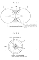
- Fig. 1 is an explanatory cross sectional view for explaining a retaining piece of a linear guide device as an example of an embodiment according to the present invention
- Fig. 2 is a right side elevational view of Fig. 1
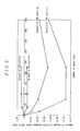
- Fig. 3 is a graph showing a relation for the amount of change of a pitch between steel balls, the number of days and the contact position of the retaining piece with the steel ball
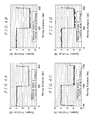
- Figs. 4A to 4D are graphs showing the fluctuation of dynamic friction in a linear guide device in a case of interposing four kinds of retaining pieces having a rigidity value lower than the existent case between the steel balls
- Fig. 1 is an explanatory cross sectional view for explaining a retaining piece of a linear guide device as an example of an embodiment according to the present invention
- Fig. 2 is a right side elevational view of Fig. 1
- Fig. 3 is a graph showing a relation for the amount of change of a pitch between steel balls, the number of days and the contact position of the retaining
- FIG. 5 is a graph showing the fluctuation of dynamic friction in a linear guide device in which an extent retaining pieces is interposed between steel balls
- Fig. 6 is a graph showing a relation between the size of peaky components and the rigidity value of the retaining piece
- Fig. 7 is a graph showing a relation between the moving distance and the amount of change for each of retaining pieces with different rigidity values
- Fig. 8 is a graph showing a relation between the rigidity value and the amount of change for each of retaining pieces. Since the linear guide device of this embodiment is different from the existent linear guide devices shown in Fig. 9 only in that the retaining piece interposed between the steel balls adjacent with each other in the rolling element endless circulation track, description is to be made only for the different portions.
- a retaining piece 100 is interposed between steel balls B adjacent with each other in a rolling element endless circulation track 7.
- the retaining piece 100 is formed into a short cylindrical shape, for example, with an elastomeric material HIGHTREL or PERPREN (trade name of products manufactured by Toyo Boseki Co.) and formed with a concaved surface 101 having a predetermined radius of curvature on both axial end faces.
- the concaved surface 101 of the retaining piece 100 is in contact with a steel ball B adjacent with the retaining piece 100 at a position for 30 to 50% of the diameter A 1 of the steel ball B (position where A 2 /A 1 x 100% is 30 to 50% in Fig. 2), and the rigidity value of the retaining piece 100 is defined as 0.054 N/ ⁇ m or more and 0.175 N/ ⁇ m or less.
- This can suppress the fluctuation of the pitch between the steel balls B due to the effect of swelling caused by oil and fats such as lubricants and can attain a further improvement of operability, low noise property and endurance, at a reduced cost and easily even in a case of using the elastomeric material as the material of the retaining piece 100.
- Fig. 3 shows the result of an immersion test in which four types of test retaining pieces were provided such that the positions of contact between the steel ball and the concaved surface of the retaining piece made of the elastomeric material were set to 70%, 60%, 50%, and 30% for the steel ball diameter respectively, and the extent of swelling caused by the lubricant (Showa Shell AV2 grease).
- the ordinate expresses the amount of dimensional change of the pitch between steel balls and the abscissa expresses a number of day lapsed in a case of using a test retaining piece.
- the amount of change of the pitch between the steel balls is within ⁇ 10 ⁇ m or less, there is no more undesired effect on the durability and undesired effect on the operability and the low noise property can be decreased remarkably. Further, in a case where the amount of change of the pitch between the steel balls is ⁇ 5 ⁇ m or less, there is no more undesired effects on the operability or the low noise property. Accordingly, the amount of change of the pitch between the steel balls is preferably ⁇ 10 ⁇ m or less and, in view of the operability and the low noise property, the amount of change of the pitch between the steel balls is more preferably ⁇ 5 ⁇ m or less.
- the retaining piece is adapted to have such a concaved shape that the steel ball adjacent with the retaining piece is in contact at a position for 50% or less of the steel ball diameter to provide a stable pitch between the steel balls, fluctuation of the pitch between the steel balls due to the effect of the swelling caused by oil and fats such as lubricants can be minimized and deterioration of the operability, low noise property and endurance due to the increase or decrease of the gap in the row of steel balls can be prevented even in a case of forming the retaining piece with the material such as the elastomeric material.
- the ground for determining the rigidity value of the retaining piece as 0.053 N/ ⁇ m or more and 0.175 N/ ⁇ m or less is to be described.
- Figs. 4A to 4D show fluctuation of dynamic friction of a linear guide device in a case of interposing four types of retaining pieces a - d having lower rigidity values than usual (rigidity value of 0.05, 0.075, 0.1, 0.2 N/ ⁇ m)
- Fig. 5 shows fluctuation of dynamic friction of a linear guide device in a case of interposing an existent retaining piece (at a rigidity value of 2 N/ ⁇ m) between the steel balls
- Fig. 6 shows a relation between the magnitude of the peaky components as a measure for the operability based on the data of Figs. 4A to 4D and Fig. 5 (minute fluctuation of dynamic friction: the operability is better as fluctuation is smaller), and the rigidity value of the retaining piece.
- the rigidity value is 0.175 N/ ⁇ m or less which is smaller than the magnitude of the peaky component of 1 N in a case of using the existent retaining piece and, accordingly, it can be seen that the operability is improved in a region where the rigidity value of the retaining piece is 0.175 N/ ⁇ m or less. Further, in view of Fig.
- Fig. 7 shows a relation between the moving distance of each of the retaining pieces and the amount of deformation that expresses the durability for retaining pieces a - d
- Fig. 8 shows a relation between the amount of change of the pitch between the steel balls and the rigidity value of the retaining piece at the moving distance of about 125 km.
- the rigidity value of the retaining piece is defined as 0.053 N/ ⁇ m or more and 0.175 N/ ⁇ m or less.
- the retaining piece having the rigidity value as described above is interposed between the rolling elements, even in a case where compressive force exerts in the row of rolling elements due to the scattering of the track length caused by fabrication errors or the like for components, it is possible to ensure the operability and noise characteristics at the level being equal with that of linear guide devices incorporated with existent retaining pieces.
- the present invention when the present invention is applied, while it is desirable that the retaining pieces of the invention are interposed between all of the steel balls, also in a case where the retaining piece of the invention is not interposed in one or small number of plural portions, the effect of improving the operability and the noise characteristics can be recognized more than the existent products not using the retaining piece of the invention.
- the portions not interposed with the retaining pieces of the invention are in symmetry with each other in view of the row of steel balls (so that not interposed portions are not in contiguous).
- the shape of the concaved surface of the retaining piece is defined as an R shape of a curvature similar with the radius of the steel ball but it is not restricted only thereto.
- the shape for the concaved surface of the retaining piece at a portion in contact with the steel ball may be a gothic shape or a conical shape, or a spherical shape such that contact may be made at the edge of the spherical surface and the steel ball. It is important for the accuracy control of the retaining piece that it has such a concaved surface shape to provide a stable pitch between steel balls upon in contact with the steel ball. Further, in a case of using the retaining piece for the linear guide device, the retaining pieces may be separated individually or connected with each other.
- a cylindrical retaining piece is used but it is not limitative and, for example, a columnar retaining piece may also be used.
- steel ball is shown as the example of the rolling element, it is not limitative but may be a ball such as of ceramic ball or the present invention is applicable also in a case of using rolls.
- the present invention is applicable also to a linear moving device such as a ball screw device, ball spline device or linear ball bush device.
Landscapes
- Engineering & Computer Science (AREA)
- General Engineering & Computer Science (AREA)
- Mechanical Engineering (AREA)
- Bearings For Parts Moving Linearly (AREA)
- Rolling Contact Bearings (AREA)
Abstract
Description
the retaining piece is in contact with the rolling element adjacent with the retaining piece at a position for 50% or less of the diameter for the rolling element.
Claims (3)
- A linear moving device comprising a guide shaft with a rolling element rolling groove and a movable member, the movable member having a rolling element rolling groove opposed to the rolling element rolling groove of the guide shaft, moving relatively being guided by the guide shaft by way of rolling motion of a plurality of rolling elements inserted between the rolling element rolling grooves, having a rolling element endless circulation track for endlessly circulating the rolling elements, and having a retaining piece intervened between each of the rolling elements adjacent with each other in the circulating direction, wherein
the retaining piece is in contact with the rolling element adjacent with the retaining piece at a position for 50% or less of the diameter for the rolling element. - A linear moving device according to claim 1, wherein the retaining piece is in contact with the rolling element adjacent with the retaining piece at a position for 30 to 50% of the diameter for the rolling element.
- A linear moving device according to claim 1 or 2, wherein a rigidity value of the retaining piece is defined as 0.053 N/µm or more and 0.175 N/µm or less.
Applications Claiming Priority (1)
| Application Number | Priority Date | Filing Date | Title |
|---|---|---|---|
| PCT/JP2002/008184 WO2004015287A1 (en) | 2002-08-09 | 2002-08-09 | Direct drive unit |
Publications (2)
| Publication Number | Publication Date |
|---|---|
| EP1528273A1 true EP1528273A1 (en) | 2005-05-04 |
| EP1528273A4 EP1528273A4 (en) | 2006-10-04 |
Family
ID=31513599
Family Applications (1)
| Application Number | Title | Priority Date | Filing Date |
|---|---|---|---|
| EP02760604A Withdrawn EP1528273A4 (en) | 2002-08-09 | 2002-08-09 | Direct drive unit |
Country Status (4)
| Country | Link |
|---|---|
| EP (1) | EP1528273A4 (en) |
| CN (1) | CN100378354C (en) |
| AU (1) | AU2002327393A1 (en) |
| WO (1) | WO2004015287A1 (en) |
Families Citing this family (2)
| Publication number | Priority date | Publication date | Assignee | Title |
|---|---|---|---|---|
| CN100578027C (en) * | 2007-04-11 | 2010-01-06 | 上银科技股份有限公司 | Linear sliding rail with synchronous connector |
| CN106402155A (en) * | 2016-11-17 | 2017-02-15 | 上海莱必泰数控机床股份有限公司 | Efficient linear guide rail |
Family Cites Families (10)
| Publication number | Priority date | Publication date | Assignee | Title |
|---|---|---|---|---|
| JPH0514009Y2 (en) * | 1987-03-26 | 1993-04-14 | ||
| JP3695195B2 (en) | 1998-06-02 | 2005-09-14 | 日本精工株式会社 | Ball screw mechanism and linear motion device |
| CN2366607Y (en) * | 1998-08-21 | 2000-03-01 | 上海达邦科工贸有限公司 | Rolling type bearing |
| JP2000203324A (en) | 1999-01-14 | 2000-07-25 | Toyota Motor Corp | Seated occupant detection device |
| JP2000274435A (en) * | 1999-03-24 | 2000-10-03 | Nsk Ltd | Rolling bearing |
| JP4459328B2 (en) * | 1999-07-28 | 2010-04-28 | 株式会社ツバキ・ナカシマ | Rolling linear motion device |
| TW412620B (en) * | 2000-03-03 | 2000-11-21 | Hiwin Tech Corp | Linear slide rail with spacer |
| JP2002021849A (en) * | 2000-07-05 | 2002-01-23 | Nsk Ltd | Linear motion bearing device |
| JP4365522B2 (en) * | 2000-10-18 | 2009-11-18 | 日本トムソン株式会社 | Linear motion guidance unit with separator connection |
| JP2003269464A (en) * | 2002-03-18 | 2003-09-25 | Nsk Ltd | Linear motion device |
-
2002
- 2002-08-09 EP EP02760604A patent/EP1528273A4/en not_active Withdrawn
- 2002-08-09 AU AU2002327393A patent/AU2002327393A1/en not_active Abandoned
- 2002-08-09 WO PCT/JP2002/008184 patent/WO2004015287A1/en not_active Ceased
- 2002-08-09 CN CNB028288033A patent/CN100378354C/en not_active Expired - Fee Related
Also Published As
| Publication number | Publication date |
|---|---|
| AU2002327393A1 (en) | 2004-02-25 |
| WO2004015287A1 (en) | 2004-02-19 |
| CN100378354C (en) | 2008-04-02 |
| CN1625658A (en) | 2005-06-08 |
| EP1528273A4 (en) | 2006-10-04 |
Similar Documents
| Publication | Publication Date | Title |
|---|---|---|
| US7000493B2 (en) | Screw device having lubricant applying portion | |
| US20030061893A1 (en) | Ball screw device and linear motion device | |
| US8100025B2 (en) | Rolling element retainer | |
| DE10101262A1 (en) | Improved linear guide bearing apparatus with separator means interleaved between adjacent ball bearings | |
| JP3263005B2 (en) | Rolling guide device | |
| JP7567627B2 (en) | Rolling guide device | |
| US7401978B2 (en) | Linear motion guiding apparatus | |
| US7090400B2 (en) | Separator, linear guide using the separator and linear motion apparatus | |
| US6941831B2 (en) | Ball screw apparatus | |
| US7021828B2 (en) | Direct drive unit | |
| US20070009188A1 (en) | Linear guide apparatus | |
| JPWO2009011282A1 (en) | Motion guide device and screw device | |
| JP2003239964A (en) | Linear motion device | |
| WO2019150923A1 (en) | Motion guiding device and method for manufacturing same | |
| JP4954065B2 (en) | Ball screw, motion guide device | |
| JP4142771B2 (en) | Ball bearing for linear motion | |
| EP1677016B1 (en) | Linear guide device | |
| CN100378354C (en) | linear moving device | |
| US20100101347A1 (en) | Roller screw and method of manufacturing the same | |
| US6655839B2 (en) | Linear guide device | |
| EP1318331B1 (en) | Ball screw apparatus | |
| DE10002818A1 (en) | Linear guide comprises balls rolling in guiding groove with endless belt around them which is moved along as they roll and spacers between them to maintain standard distance | |
| JP4372320B2 (en) | Combination of rollers, roller screw using the combination, and rolling guide device | |
| US5649769A (en) | Linear motion rolling guide unit | |
| US5490729A (en) | Ball spline |
Legal Events
| Date | Code | Title | Description |
|---|---|---|---|
| PUAI | Public reference made under article 153(3) epc to a published international application that has entered the european phase |
Free format text: ORIGINAL CODE: 0009012 |
|
| 17P | Request for examination filed |
Effective date: 20040526 |
|
| AK | Designated contracting states |
Kind code of ref document: A1 Designated state(s): AT BE BG CH CY CZ DE DK EE ES FI FR GB GR IE IT LI LU MC NL PT SE SK TR |
|
| AX | Request for extension of the european patent |
Extension state: AL LT LV MK RO SI |
|
| DAX | Request for extension of the european patent (deleted) | ||
| RBV | Designated contracting states (corrected) |
Designated state(s): DE GB |
|
| A4 | Supplementary search report drawn up and despatched |
Effective date: 20060831 |
|
| 17Q | First examination report despatched |
Effective date: 20070730 |
|
| STAA | Information on the status of an ep patent application or granted ep patent |
Free format text: STATUS: THE APPLICATION HAS BEEN WITHDRAWN |
|
| 18W | Application withdrawn |
Effective date: 20090511 |