EP1528161A2 - Access covers - Google Patents
Access covers Download PDFInfo
- Publication number
- EP1528161A2 EP1528161A2 EP04256683A EP04256683A EP1528161A2 EP 1528161 A2 EP1528161 A2 EP 1528161A2 EP 04256683 A EP04256683 A EP 04256683A EP 04256683 A EP04256683 A EP 04256683A EP 1528161 A2 EP1528161 A2 EP 1528161A2
- Authority
- EP
- European Patent Office
- Prior art keywords
- cover
- extension
- plate
- roof
- pillar
- Prior art date
- Legal status (The legal status is an assumption and is not a legal conclusion. Google has not performed a legal analysis and makes no representation as to the accuracy of the status listed.)
- Withdrawn
Links
- 230000000295 complement effect Effects 0.000 claims description 3
- 230000002093 peripheral effect Effects 0.000 claims description 3
- 238000010276 construction Methods 0.000 claims description 2
- 210000002105 tongue Anatomy 0.000 description 12
- 238000004378 air conditioning Methods 0.000 description 2
- 238000000034 method Methods 0.000 description 2
- 239000000446 fuel Substances 0.000 description 1
- 238000009434 installation Methods 0.000 description 1
- 238000004519 manufacturing process Methods 0.000 description 1
- 239000002184 metal Substances 0.000 description 1
- 230000037361 pathway Effects 0.000 description 1
- 230000000737 periodic effect Effects 0.000 description 1
- 238000000926 separation method Methods 0.000 description 1
- 239000000758 substrate Substances 0.000 description 1
- 238000003466 welding Methods 0.000 description 1
Images



Classifications
-
- E—FIXED CONSTRUCTIONS
- E02—HYDRAULIC ENGINEERING; FOUNDATIONS; SOIL SHIFTING
- E02D—FOUNDATIONS; EXCAVATIONS; EMBANKMENTS; UNDERGROUND OR UNDERWATER STRUCTURES
- E02D29/00—Independent underground or underwater structures; Retaining walls
- E02D29/12—Manhole shafts; Other inspection or access chambers; Accessories therefor
- E02D29/14—Covers for manholes or the like; Frames for covers
Definitions
- the invention relates to access covers, in particular, to covers which are able to bear loads or which are load bearing.
- An access cover comprises a main body of metal in a frame which is secured to the edge of a hole in a substrate.
- the hole may contain utility equipment or air conditioning equipment or the like. Often, such an access hole is in a pedestrian or vehicle pathway and there is a need to provide a cover which can withstand a heavy applied load, e.g. a laden truck or trailer.
- a load-bearing cover for an access hole, the cover comprising a plurality of plates joined in side-by-side relation, each plate comprising a generally planar body, each plate having at one side a tongue extension in the form of a depending post from a side of which extends a generally horizontal ledge below and parallel to the plate body, the plate having at the opposite side an extension projecting beyond the plate, the extension depending from the plate and having a groove portion shaped and dimensioned to receive and engage the tongue of the neighbouring plate.
- the lower end of the groove extension comprises a socket to receive the head portion of a load-bearing pillar; preferably the pillar has a T-shaped head to be received in a complementary socket in the groove extension.
- the pillar has a foot portion adapted to engage a bridge member at each side whereby adjacent pillars may be joined together at their foot.
- the invention provides a load-bearing cover for an access hole, the cover comprising a plurality of box sections joined in side-by-side relation, each section comprising a generally planar roof, each roof having at one side a tongue extension in the form of a depending post from a side of which extends a generally horizontal ledge below and parallel to the roof, the roof having at the opposite side an extension projecting beyond the roof, the extension depending from the roof and having a groove portion shaped and dimensioned to receive and engage the tongue extension of the neighbouring roof, the lower end of the groove extension comprising a socket which receives the head portion of a pillar to define a side wall of the box section, the pillar having a foot portion which engages a bridge member at each side to define a floor of the box section.
- the tongue and groove extensions extend the full width of the cover roof, but the pillar is of reduced length, leaving a gap at each end.
- a connector is received in each of those gaps and is adapted to connect the cover to a peripheral frame to form a unitary construction.
- the invention also extends to weld-free methods of assembling the cover, as disclosed herein.
- An access hole may have a span of about 4 metres and has a cover C which is designed to withstand an applied load in excess of 11 tonnes, for example, from the wheel of a heavily laden goods transporter.
- the access hole may contain fuel pipes, e.g. for the refuelling of ships, or utility services or major installations in need of periodic servicing such as air conditioning units.
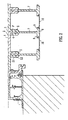
- the cover C is made up of three rectangular bodies each of which consists of a row of interlinked box sections B. Each has a plate or roof 1, the upper surface of which is the exposed surface; this may have deformations 2 to prevent skidding or the like. At one side the plate 1 has a depending leg 3 which ends in a rectangular foot 4 below the plate 1 which defines a tongue or peg type connector P; at the other side the plate 1 has a longer leg 5 which projects below and beyond the edge of the plate 1 to define a socket S having two socket parts S1, S2.
- the first and upper socket part S1 is a groove or U-shaped to complement the tongue P of the neighbouring plate so that when the tongue P and the socket part S1 are engaged a locked connection is formed.
- the second and lower socket part S2 is shaped and dimensioned to receive the head 6 of a T-shaped pillar 7 in locking fashion; the engagement of this socket S2 and the head 6 of the pillar 7 is immediately below the connection of tongue P and groove part socket S1.
- the pillars 7 form the sides of the box sections B.
- the pillar 7 has a foot 8 with side extensions 9 and these engage with locking members 10 on each side to provide the floor of the box section. Because the pillar 7 is detachable from the socket part S2, pillars 7 of different load bearing capacity can be fitted according to local requirement.
- the tongues P and groove sockets S extend across the roof (as shown in Figure 4) from one side to the other but the pillars 7 are shorter. At each end a connector 11 is inserted to fill the gap.
- the connector is shown in Figure 3 and comprises a T-shaped head 12 and a body 13 having two side slots 14.
- the head 12 is about half the width of the connector body 13 to define a slot 15 to receive an end portion of the adjacent pillar.
- a frame 20 surrounds the underside the cover and this has four walls each having a longitudinal slot 21.
- the head 22 of a bolt 23 is received in the slot 21 and the shank passes through a side slot 14 of the connector 11 and has a nut 24 at the other end. Two such bolts 23 are present, one per slot 14 of the connectors 11. In this way the cover (C) is connected to its frame.
- One side of the frame is connected by hinges to the perimeter of the access hole in known fashion.
- the tongue P and groove S1 connection is of a locking type and the same applies to the connection of the socket S2 and pillar 7, the components will not separate when a heavy load is applied to the top of the cover. Instead, the box section beams of the cover will deflect under the load as a unit and there will be little, if any, separation of the components. This contrasts with a welded system in which the weld connections are liable to break.
- the cover C is built up from the underside.
- the plates 1 are joined together in side-by-side relation by connecting the tongue P to the groove socket parts S1.
- the pillars 7 are then added followed by the connectors 11 to join the pillars to the frame 20. All the connections are made by sliding parts together to join them in locking fashion but no welding is required. This reduces the manufacturing time substantially compared to known techniques of assembling a load bearing cover. It also means that components can be replaced or substituted as required, according to requirements.
- the invention is not limited to the embodiment shown.
- the engagement of the components may be any locking system which is capable of easy assembly. Fittings may be present, examples being gas springs, locks and the like.
Landscapes
- Engineering & Computer Science (AREA)
- Environmental & Geological Engineering (AREA)
- Life Sciences & Earth Sciences (AREA)
- General Life Sciences & Earth Sciences (AREA)
- Mining & Mineral Resources (AREA)
- Paleontology (AREA)
- Civil Engineering (AREA)
- General Engineering & Computer Science (AREA)
- Structural Engineering (AREA)
- Body Structure For Vehicles (AREA)
- Roof Covering Using Slabs Or Stiff Sheets (AREA)
Abstract
Description
Claims (8)
- A load-bearing cover (C) for an access hole, the cover (C) comprising a plurality of plates (1) joined in side-by-side relation, each plate (1) comprising a generally planar body, each plate (1) having at one side a tongue extension (P) in the form of a depending post (3) from a side of which extends a generally horizontal ledge (4) below and parallel to the plate (1) body, the plate (1) having at the opposite side an extension (5) projecting beyond the plate (1), the extension (5) depending from the plate (1) and having a groove portion (S1) shaped and dimensioned to receive and engage the ledge (4) of the neighbouring plate (1).
- A cover (C) according to Claim 1, wherein the lower end of the extension (5) comprises a socket (S2) in which is received or receivable the head portion (6) of a load-bearing pillar (7).
- A cover (C) according to Claim 2, wherein the pillar (7) has a T-shaped head (6) to receive, or in which is receivable, a complementary socket (S2) in the extension (5).
- A cover (C) according to Claim 2 or 3, wherein the pillar (7) has a foot portion (8) adapted to engage a bridge member (10) at each side (9) whereby adjacent pillars (7) are joined or joinable together at their foot portions (8).
- A cover (C) according to any of Claims 2, 3 or 4, wherein the pillar (7) does not extend the full width of the cover (C) and connectors (11) are present at each end.
- A cover (C) according to Claim 5, wherein the connectors (11) connect, or enable connection of, the cover (C) to a peripheral frame.
- A load-bearing cover (C) for an access hole, the cover (C) comprising a plurality of box sections (B) joined in side-by-side relation, each section (B) comprising a generally planar roof (1), each roof (1) having at one side a tongue extension (P) in the form of a depending post (3) from a side of which extends a generally horizontal ledge (4) below and parallel to the roof (1), the roof (1) having at the opposite side an extension (5) projecting beyond the roof (1), the extension (5) depending from the roof (1) and having a groove portion (S1) shaped and dimensioned to receive and engage the tongue extension (P) of the neighbouring roof (1), the lower end of the groove extension (5) comprising a socket (S2) which receives the head portion (6) of a pillar (7) to define a side wall of the box section (B), the pillar (7) having a foot portion (8) which engages a bridge member (10) at a side to define a floor of the box section (B).
- A cover (C) according to Claim 7, wherein the tongue (P) and groove extensions (5) extend the full width of the cover roof but the pillars (7) are of reduced length, leaving a gap at each end in which a connector (11) is received or receivable and which connects or enables connection of, the cover (C) to a peripheral frame to form a unitary construction.
Applications Claiming Priority (2)
| Application Number | Priority Date | Filing Date | Title |
|---|---|---|---|
| GB0325387 | 2003-10-30 | ||
| GB0325387A GB2407605A (en) | 2003-10-30 | 2003-10-30 | Load-bearing cover for an access hole |
Publications (2)
| Publication Number | Publication Date |
|---|---|
| EP1528161A2 true EP1528161A2 (en) | 2005-05-04 |
| EP1528161A3 EP1528161A3 (en) | 2006-01-11 |
Family
ID=29725671
Family Applications (1)
| Application Number | Title | Priority Date | Filing Date |
|---|---|---|---|
| EP04256683A Withdrawn EP1528161A3 (en) | 2003-10-30 | 2004-10-28 | Access covers |
Country Status (2)
| Country | Link |
|---|---|
| EP (1) | EP1528161A3 (en) |
| GB (1) | GB2407605A (en) |
Families Citing this family (2)
| Publication number | Priority date | Publication date | Assignee | Title |
|---|---|---|---|---|
| CN101586348B (en) * | 2008-05-22 | 2013-07-03 | 王基坜 | Embedded type well tool |
| CN103452140B (en) * | 2013-09-11 | 2015-06-24 | 青岛林川工程技术咨询有限公司 | Manhole cover system for airport and its application method |
Family Cites Families (5)
| Publication number | Priority date | Publication date | Assignee | Title |
|---|---|---|---|---|
| US3555762A (en) * | 1968-07-08 | 1971-01-19 | Aluminum Plastic Products Corp | False floor of interlocked metal sections |
| US3884328A (en) * | 1973-10-01 | 1975-05-20 | Chester I Williams | Scaffold plank |
| US5185193A (en) * | 1991-01-04 | 1993-02-09 | Case Designers Corporation | Interlockable structural members and foldable double wall containers assembled therefrom |
| JPH1060933A (en) * | 1996-08-16 | 1998-03-03 | Kajima Corp | manhole |
| ITTO20010715A1 (en) * | 2001-07-20 | 2003-01-20 | Fonderie Viterbesi Di Belli & | COVER FOR ROAD FLOOR INSPECTION. |
-
2003
- 2003-10-30 GB GB0325387A patent/GB2407605A/en not_active Withdrawn
-
2004
- 2004-10-28 EP EP04256683A patent/EP1528161A3/en not_active Withdrawn
Also Published As
| Publication number | Publication date |
|---|---|
| GB2407605A (en) | 2005-05-04 |
| GB0325387D0 (en) | 2003-12-03 |
| EP1528161A3 (en) | 2006-01-11 |
Similar Documents
| Publication | Publication Date | Title |
|---|---|---|
| US10344436B2 (en) | Modular access structure | |
| US4226465A (en) | Load supporting frame assembly | |
| US20210194409A1 (en) | Adjustment fitting and carrier system for solar panels | |
| US3080021A (en) | Floor structure | |
| US6082810A (en) | Cargo vehicle floor construction and method | |
| US20180001940A1 (en) | Cargo body and method of assembling the same | |
| US8506005B2 (en) | Trailer floor having extruded panels | |
| US20030164112A1 (en) | Undercar assembly for a railcar | |
| US20230382471A1 (en) | Spline joints and container having same | |
| US20040221533A1 (en) | Floor structure | |
| US20080272164A1 (en) | Roof rack for vehicles | |
| CA2586858A1 (en) | System and method for fastening floor deck to semi-trailer cross members | |
| JPWO2012081697A1 (en) | Container and connecting jig for container | |
| WO2009082274A1 (en) | Attachment arrangement | |
| KR20120042984A (en) | Pallet that can be assembled with sliding boards and a locking spine member | |
| KR102000114B1 (en) | Modular truss girder for temporary bridge and installation structure thereof | |
| GB2407605A (en) | Load-bearing cover for an access hole | |
| US7065926B2 (en) | Manufactured home frame | |
| US5979139A (en) | Lightweight, self-supporting paneling | |
| US5547321A (en) | Combined sidewall and tie-down for pallet | |
| RU2494889C2 (en) | Vehicle detachable step | |
| US4549833A (en) | Frame members for supporting covers or gratings | |
| GB2234991A (en) | Demountable flooring, platforms and staging | |
| CN105164007A (en) | Modular floor for a utility vehicle and method for producing said modular floor | |
| CN222009647U (en) | Primary and secondary beam connection structure and overhanging type unloading platform |
Legal Events
| Date | Code | Title | Description |
|---|---|---|---|
| PUAI | Public reference made under article 153(3) epc to a published international application that has entered the european phase |
Free format text: ORIGINAL CODE: 0009012 |
|
| AK | Designated contracting states |
Kind code of ref document: A2 Designated state(s): AT BE BG CH CY CZ DE DK EE ES FI FR GB GR HU IE IT LI LU MC NL PL PT RO SE SI SK TR |
|
| AX | Request for extension of the european patent |
Extension state: AL HR LT LV MK |
|
| PUAL | Search report despatched |
Free format text: ORIGINAL CODE: 0009013 |
|
| AK | Designated contracting states |
Kind code of ref document: A3 Designated state(s): AT BE BG CH CY CZ DE DK EE ES FI FR GB GR HU IE IT LI LU MC NL PL PT RO SE SI SK TR |
|
| AX | Request for extension of the european patent |
Extension state: AL HR LT LV MK |
|
| 17P | Request for examination filed |
Effective date: 20060706 |
|
| AKX | Designation fees paid |
Designated state(s): AT BE BG CH CY CZ DE DK EE ES FI FR GB GR HU IE IT LI LU MC NL PL PT RO SE SI SK TR |
|
| 17Q | First examination report despatched |
Effective date: 20080215 |
|
| STAA | Information on the status of an ep patent application or granted ep patent |
Free format text: STATUS: THE APPLICATION IS DEEMED TO BE WITHDRAWN |
|
| 18D | Application deemed to be withdrawn |
Effective date: 20080926 |