EP1527995B1 - Kühlereinheit - Google Patents
Kühlereinheit Download PDFInfo
- Publication number
- EP1527995B1 EP1527995B1 EP20040025444 EP04025444A EP1527995B1 EP 1527995 B1 EP1527995 B1 EP 1527995B1 EP 20040025444 EP20040025444 EP 20040025444 EP 04025444 A EP04025444 A EP 04025444A EP 1527995 B1 EP1527995 B1 EP 1527995B1
- Authority
- EP
- European Patent Office
- Prior art keywords
- valve
- air
- opening
- drain
- chiller unit
- Prior art date
- Legal status (The legal status is an assumption and is not a legal conclusion. Google has not performed a legal analysis and makes no representation as to the accuracy of the status listed.)
- Expired - Lifetime
Links
Images


Classifications
-
- B—PERFORMING OPERATIONS; TRANSPORTING
- B64—AIRCRAFT; AVIATION; COSMONAUTICS
- B64D—EQUIPMENT FOR FITTING IN OR TO AIRCRAFT; FLIGHT SUITS; PARACHUTES; ARRANGEMENT OR MOUNTING OF POWER PLANTS OR PROPULSION TRANSMISSIONS IN AIRCRAFT
- B64D11/00—Passenger or crew accommodation; Flight-deck installations not otherwise provided for
- B64D11/04—Galleys
-
- B—PERFORMING OPERATIONS; TRANSPORTING
- B64—AIRCRAFT; AVIATION; COSMONAUTICS
- B64D—EQUIPMENT FOR FITTING IN OR TO AIRCRAFT; FLIGHT SUITS; PARACHUTES; ARRANGEMENT OR MOUNTING OF POWER PLANTS OR PROPULSION TRANSMISSIONS IN AIRCRAFT
- B64D13/00—Arrangements or adaptations of air-treatment apparatus for aircraft crew or passengers, or freight space
- B64D13/06—Arrangements or adaptations of air-treatment apparatus for aircraft crew or passengers, or freight space the air being conditioned
-
- F—MECHANICAL ENGINEERING; LIGHTING; HEATING; WEAPONS; BLASTING
- F24—HEATING; RANGES; VENTILATING
- F24F—AIR-CONDITIONING; AIR-HUMIDIFICATION; VENTILATION; USE OF AIR CURRENTS FOR SCREENING
- F24F13/00—Details common to, or for air-conditioning, air-humidification, ventilation or use of air currents for screening
- F24F13/22—Means for preventing condensation or evacuating condensate
- F24F13/222—Means for preventing condensation or evacuating condensate for evacuating condensate
-
- B—PERFORMING OPERATIONS; TRANSPORTING
- B64—AIRCRAFT; AVIATION; COSMONAUTICS
- B64D—EQUIPMENT FOR FITTING IN OR TO AIRCRAFT; FLIGHT SUITS; PARACHUTES; ARRANGEMENT OR MOUNTING OF POWER PLANTS OR PROPULSION TRANSMISSIONS IN AIRCRAFT
- B64D13/00—Arrangements or adaptations of air-treatment apparatus for aircraft crew or passengers, or freight space
- B64D13/06—Arrangements or adaptations of air-treatment apparatus for aircraft crew or passengers, or freight space the air being conditioned
- B64D2013/0603—Environmental Control Systems
- B64D2013/0629—Environmental Control Systems with subsystems for cooling food, catering or special loads
-
- B—PERFORMING OPERATIONS; TRANSPORTING
- B64—AIRCRAFT; AVIATION; COSMONAUTICS
- B64D—EQUIPMENT FOR FITTING IN OR TO AIRCRAFT; FLIGHT SUITS; PARACHUTES; ARRANGEMENT OR MOUNTING OF POWER PLANTS OR PROPULSION TRANSMISSIONS IN AIRCRAFT
- B64D13/00—Arrangements or adaptations of air-treatment apparatus for aircraft crew or passengers, or freight space
- B64D13/06—Arrangements or adaptations of air-treatment apparatus for aircraft crew or passengers, or freight space the air being conditioned
- B64D2013/0603—Environmental Control Systems
- B64D2013/0674—Environmental Control Systems comprising liquid subsystems
-
- F—MECHANICAL ENGINEERING; LIGHTING; HEATING; WEAPONS; BLASTING
- F16—ENGINEERING ELEMENTS AND UNITS; GENERAL MEASURES FOR PRODUCING AND MAINTAINING EFFECTIVE FUNCTIONING OF MACHINES OR INSTALLATIONS; THERMAL INSULATION IN GENERAL
- F16K—VALVES; TAPS; COCKS; ACTUATING-FLOATS; DEVICES FOR VENTING OR AERATING
- F16K15/00—Check valves
- F16K15/14—Check valves with flexible valve members
- F16K15/144—Check valves with flexible valve members the closure elements being fixed along all or a part of their periphery
Definitions
- the present invention relates to an air chiller unit (air cooling device) equipped within a body of an aircraft, for supplying cooled air to foods or the like.
- Passenger aircrafts that travel long distances, such as international flights, are equipped with service carts storing meals etc. to be served to passengers, and galleys (kitchen areas) storing the service carts for preparing beverages and doing easy food preparation.
- the meals are cooked in advance in service facilities on the ground, placed on trays to be stored in service carts, and brought on board.
- Patent Document 1 USP No. 5491979
- the air chiller unit is equipped with an evaporator for heat exchange disposed within a refrigeration cycle unit, dew condensation tends to occur on the surface of the evaporator.
- the dew condensation drips from the evaporator in forms of water drops.
- the water drops are received by a drain pan, and discharged through a drain.
- the noise generated inside the air chiller unit is leaked through the drain to the passenger cabin, and highly moist outside air enters the air chiller unit through the drain, causing further dew condensation.
- the present invention provides an air chiller unit equipped with a drain valve that automatically opens and closes according to the operation status of the air chiller unit.
- the air chiller unit includes a refrigeration cycle unit, a casing for storing the refrigeration cycle unit, a drain pan for receiving the dew condensation on an evaporator in the refrigeration cycle unit, and a drain valve disposed on a drain of the drain pan.
- the drain valve is equipped with a ring-shaped valve seat member having an opening at the center thereof, and a valve member disposed underneath the valve seat member for opening and closing the opening of the valve seat member.
- the valve member is made of a thin silicon rubber material, and the valve means for opening and closing the opening of the valve seat member is designed to contact the opening of the valve seat member with a small spring constant.
- the present air chiller unit is equipped with a drain valve disposed on the drain of the drain pan for receiving water drops condensed on the evaporator in the refrigeration cycle unit, and discharges the water only when water exists.
- the valve is closed to prevent outside moisture from entering.
- dew condensation can be reduced, and the number of times for dehumidifying the device can be reduced.
- the drain valve is closed due to negative pressure, preventing noise from leaking.
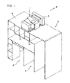
- FIG. 1 is an explanatory view showing the general structure of a galley equipped with an air chiller unit according to the present invention.
- the galley denoted as a whole by reference number 2 is formed of panel members, and equipped with multiple shelves and storages for storing cooking devices and the like.
- Storage spaces 3 provided on the floor of the galley 2 are for storing service carts (not shown) storing trays for meals.
- the air chiller unit 1 is not exposed to the cabin, and is arranged in the ceiling of the aircraft.
- Arrow F of FIG. 1 shows the front direction of the aircraft body, and a passage for cooled air for cooling the service cart is formed on the back side of the galley 2 positioned at the forward direction of the aircraft body.
- the cool air circulated within the galley is recycled to the air chiller unit 1, where it is cooled to predetermined temperature and sent out into the galley again.
- a duct device 5 connected to the air chiller unit 1 is equipped with a passage returning from the interior of the galley and a passage for sending freshly cooled air toward the galley.
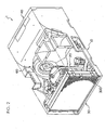
- FIGS. 2 and 3 are explanatory views showing the exterior of the air chiller unit according to the present invention and the general structure of the refrigeration cycle unit.
- An air chiller unit referred to as a whole by reference number 1 is equipped with a casing 10, a compressor 20 for a refrigerant disposed within the casing 10, a condenser 30, an evaporator 40 and a blower device 60 for blowing air.
- the refrigeration cycle unit of the air chiller unit is equipped with a compressor 20 driven by a motor, for compressing the refrigerant and sending out the same toward the condenser 30.
- the condenser 30 is equipped with a heat exchanger 300 for exchanging the gaseous refrigerant to a liquid-phase refrigerant.
- the liquid-phase refrigerant is stored in a receiver drier 310 disposed adjacent to the heat exchanger.
- the liquid-phase refrigerant in the receiver drier 310 is sent via a piping to an evaporator 40 disposed within the air cooling chamber defined by the wall of the casing 10.
- the liquid-phase refrigerant travels through an expansion valve 410 equipped to the evaporator 40 and sent to a heat exchanger 400 of the evaporator.
- the refrigerant is then evaporated in the heat exchanger 400 and cools the air passing through the heat exchanger 400.
- the expansion valve 410 changes the opening of the valve according to the pressure and temperature of the refrigerant returning toward the compressor 20 from the evaporator 40, to thereby control the flow rate of the refrigerant being sent to the evaporator.
- the blower device 60 has two fans mounted on both ends of a shaft of a motor, and blows air toward the condenser 30 and also blows the cooled air generated in the air cooling chamber toward the service carts placed in the passenger cabin.
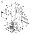
- FIGS. 4 and 5 are explanatory views showing the structure of a casing of the air chiller unit according to the present invention.
- the casing 10 comprises a base plate 100, and on the base plate 100 are mounted devices such as the compressor 20.
- Thebaseplate 100 is formed of a honeycomb panel manufactured by sandwiching a core member having a honeycomb structure between two parallel plate members.
- the honeycomb panel is light weight and has superior flexural rigidity, so the base plate 100 is capable of supporting devices such as the compressor 20 by itself.
- the honeycomb panel Since the honeycomb panel is formed to have air sealed in the honeycomb core, it has high heat insulating property. Therefore, it is suitable for forming the air cooling chamber or the like.
- Apartitionmember 110 formedof ahoneycombpanel is disposed on the base plate 100.
- This partition member 110 is for dividing the air chiller unit into a side having the condenser and a side having the evaporator, and on this partitionmember 110 is mounted the blower device 60.
- the partition member constitutes a portion of the air cooling chamber 130.
- a lid member 120 is mounted on the opening of the partition member 110.
- the lid member 120 connected to a duct device 5 is equipped with a first opening 122 and a second opening 124.
- the first opening 122 is connected to a passage for sending the cool air returning from the galley to the air cooling chamber 130
- the second opening 124 is connected to a passage for sending the freshly cooled air cooled in the air cooling chamber 130 toward the galley.
- a cover member 140 is mounted above the base plate 100, by which the compressor 20 and the blower device 60 are covered.
- the cover member 140 has rectangular openings 144 and 146 on the upper surface and side surface thereof. The openings 144 and 146 are used as exhaust outlets of air having cooled the condenser 30 and the compressor 20.
- a mesh member 148 is attached to the end of the cover member 140, by which the front face of the condenser 30 is covered.
- a round hole 142 for the blower device is provided to the partition member 110. Further, a drain pan 150 for receiving water drops condensed on the evaporator is attached to the bottom of the air cooling chamber.
- the drain pan 150 is equipped with a drain valve 160.
- FIG. 6 is an explanatory view showing the structure of the blower device 60.
- the blower device 60 has a housing 630 constituting a passage for sending out cooled air, and a motor 600 disposed within the housing 630.
- the motor 600 has a drive shaft 602 whose both ends protrude therefrom, and on both ends of the driving shaft are fixed a first fan 610 and a second fan 620.
- the first fan 610 is for sending the air for cooling the side having the condenser 30.
- the second fan 620 is for blowing the air cooled in the air cooling chamber toward the galley.
- the opening of the housing 630 is covered with a cover 640.
- An opening portion 642 of the cover 640 is connected to the second opening 124 of the lid member 120 for sending the freshly cooled air toward the galley.
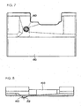
- FIG. 7 is a plan view of the drain pan 150 for receiving dew drops from the evaporator
- FIG. 8 is a front view thereof.
- the drain pan 150 has a drain 152 opening to the bottom portion thereof, and a drain valve 160 attached to the upper portion of the drain 152.
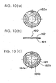
- FIG. 9 shows a plan view and a cross-sectional view of the drain valve 160.
- the drain valve 160 is composed of a ring-shaped valve seat member 162 made from a metal plate, and a valve member 164 gripped by the valve seat member.
- FIG. 10 shows the structure of a drain valve 160.
- the valve seat member 162 has a round opening 162a formed to the center thereof, and a bent portion 162b formed to the outer circumference thereof for gripping the valve member 164.
- FIG. 11 shows the plan shape of the valve member 164.
- the valve member 164 is formed by creating three slits 164a on a thin silicon rubber disk. Three arms 164b defined by the three slits 164a support the valve means 164e at the center portion.
- the valve means 164e is elastically supported with small spring constant by the very flexible arms 164b formed of thin silicon rubber.
- the blower device 60 sends the cooled air within the air cooling chamber 130 toward the galley, so the interior of the air cooling chamber 130 becomes negative pressure.
- the valve means 164e of the valve member 164 in the drain valve 160 is sucked toward the valve seat member 162 and shuts the opening 162a of the valve seat member 162.
- the drain valve 160 is shut, preventing highly moist outside air from entering the device and also preventing noise generated in the air chiller unit from leaking to the exterior.
- frost occurs on the surface of the evaporator, deteriorating the cooling effect.
- frost removal cycle in which high-temperature refrigerant is sent into the evaporator.
- valve means 164e When the water on the valve means 164e are gone, the valve means returns to the position shutting the opening 162a of the valve seat member 162, preventing outside moist from entering.
- the drain valve is closed at once, preventing highlymoist outside air from entering and noise from leaking to the exterior.
Landscapes
- Engineering & Computer Science (AREA)
- Aviation & Aerospace Engineering (AREA)
- Health & Medical Sciences (AREA)
- Combustion & Propulsion (AREA)
- Mechanical Engineering (AREA)
- General Engineering & Computer Science (AREA)
- Chemical & Material Sciences (AREA)
- General Health & Medical Sciences (AREA)
- Pulmonology (AREA)
- Removal Of Water From Condensation And Defrosting (AREA)
- Cold Air Circulating Systems And Constructional Details In Refrigerators (AREA)
- Lift Valve (AREA)
- Self-Closing Valves And Venting Or Aerating Valves (AREA)
Claims (1)
- Luftkühler-Einheit, die in einem Flugzeug zur Zuleitung gekühlter Luft zu einem Lagerbereich zur Lagerung von Nahrungsmitteln oder dergleichen anbringbar ist, umfassend:eine Kühlmittelkreislauf-Einheit;ein Gehäuse (10) zur Aufnahme der Kühlmittelkreislauf-Einheit; undeine Tropfwanne (150) zur Aufnahme von Kondensationswasser, die an einem Verdampfer (40) der Kühlmittelkreislauf-Einheit vorgesehen ist;ferner gekennzeichnet durch ein Ablaufventil (160), das an einem Ablauf der Tropfwanne (150) angebracht ist, welches Ablaufventil (160) mit einem ringförmigen Ventilsitzelement (162) versehen ist, das in seinem Mittelbereich eine Öffnung aufweist, wobei ein Ventilelement (164) unterhalb des Ventilsitzelements (162) zum Öffnen und Schliessen der Öffnung des Ventilsitzelements (162) angeordnet ist,wobei das Ventilsitzelement (164) aus einem dünnen Silikon-Element besteht und ein Ventilorgan (164e) und drei Arme (164b) zum Halten des Ventilorgans (164e) im Mittelbereich des Ventilelements (164) umfasst, welches Ventilorgan (164e) zum Öffnen und Schliessen der Öffnung des Ventilsitzelements (162) vorgesehen ist und zur Berührung der Öffnung des Ventilsitzelements (162) mit einer kleinen Federkonstante gestaltet ist, zum Auslassen der Wassertropfen in der Tropfwanne (150), wenn das Gebläse der Luftkühlereinheit angehalten ist, wobei dann, wenn das Gebläse der Luftkühlereinheit wieder gestartet ist, das Entwässerungsventil (160) sofort geschlossen wird, damit keine Luft von aussen eindringt.
Applications Claiming Priority (2)
| Application Number | Priority Date | Filing Date | Title |
|---|---|---|---|
| JP2003368299A JP2005134002A (ja) | 2003-10-29 | 2003-10-29 | エアチラー装置 |
| JP2003368299 | 2003-10-29 |
Publications (3)
| Publication Number | Publication Date |
|---|---|
| EP1527995A2 EP1527995A2 (de) | 2005-05-04 |
| EP1527995A3 EP1527995A3 (de) | 2006-10-18 |
| EP1527995B1 true EP1527995B1 (de) | 2008-03-19 |
Family
ID=34420150
Family Applications (1)
| Application Number | Title | Priority Date | Filing Date |
|---|---|---|---|
| EP20040025444 Expired - Lifetime EP1527995B1 (de) | 2003-10-29 | 2004-10-26 | Kühlereinheit |
Country Status (4)
| Country | Link |
|---|---|
| US (1) | US7174739B2 (de) |
| EP (1) | EP1527995B1 (de) |
| JP (1) | JP2005134002A (de) |
| DE (1) | DE602004012509T2 (de) |
Families Citing this family (11)
| Publication number | Priority date | Publication date | Assignee | Title |
|---|---|---|---|---|
| US8720217B2 (en) * | 2006-07-10 | 2014-05-13 | Mag Aerospace Industries, Inc. | Galley cooling heat sink through water system |
| DE202006013229U1 (de) * | 2006-08-29 | 2006-10-26 | BSH Bosch und Siemens Hausgeräte GmbH | Kältegerät mit Druckausgleichsventil |
| US8839630B2 (en) * | 2008-10-17 | 2014-09-23 | Hoffman Enclosures, Inc. | Thermoelectric dehumidifier and enclosure vent drain assembly |
| EP2879551B1 (de) | 2012-08-01 | 2016-12-28 | Carrier Corporation | Verkaufskühlvitrine |
| US9359076B2 (en) * | 2013-02-11 | 2016-06-07 | B/E Aerospace, Inc. | Compact aircraft galley and lavatory arrangement and articulating lavatory partition for an aircraft |
| CN106133465A (zh) * | 2014-03-24 | 2016-11-16 | B/E航空公司 | 具有液体散热系统的交通工具制冷设备 |
| DE102017130722A1 (de) * | 2017-12-20 | 2019-06-27 | Airbus Operations Gmbh | Flugzeugbordküche |
| CN107940729A (zh) * | 2017-12-22 | 2018-04-20 | 广东美的制冷设备有限公司 | 空调器的排水管组件及空调器 |
| US11286049B2 (en) | 2019-11-12 | 2022-03-29 | B/E Aerospace, Inc. | Standard unit meal box compartment including air chiller |
| WO2022172376A1 (ja) * | 2021-02-10 | 2022-08-18 | 三菱電機株式会社 | 熱交換換気装置 |
| CN115164286B (zh) * | 2022-06-13 | 2023-09-29 | 泰豪科技股份有限公司 | 一种空调外机散热铜管除霜组件 |
Family Cites Families (12)
| Publication number | Priority date | Publication date | Assignee | Title |
|---|---|---|---|---|
| GB1272756A (en) * | 1968-07-13 | 1972-05-03 | Gen Motors Ltd | Liquid filter units |
| US3845779A (en) * | 1973-05-10 | 1974-11-05 | Waldon Devices Inc | Garden hose evacuating device |
| US4361014A (en) * | 1981-03-19 | 1982-11-30 | Sundstrand Corporation | Panel air chiller |
| US4843835A (en) * | 1988-09-27 | 1989-07-04 | Amana Refrigeration, Inc. | Refrigerator drain funnel |
| KR930006392A (ko) * | 1991-09-02 | 1993-04-21 | 이우에 사또시 | 공기 조화기 |
| DE4340317C2 (de) * | 1993-11-26 | 1996-03-21 | Daimler Benz Aerospace Airbus | Kühlsystem zur Kühlung von Lebensmitteln in einem Flugzeug |
| DE4340316C2 (de) | 1993-11-26 | 1996-03-21 | Daimler Benz Aerospace Airbus | Anordnung zur Kühlung von Lebensmitteln in einem Flugzeug |
| US5797426A (en) * | 1997-04-10 | 1998-08-25 | Powell; Edwin O. | Check valve and trap assembly |
| US6301917B1 (en) * | 1998-06-11 | 2001-10-16 | Marvin Lacoste | Condensate blowout tool |
| US6334761B1 (en) * | 2000-03-02 | 2002-01-01 | California Institute Of Technology | Check-valved silicon diaphragm pump and method of fabricating the same |
| FR2820196B1 (fr) * | 2001-01-29 | 2006-12-29 | Claude Antoine Blaizat | Procede de maintien sous froid des trolleys a bord des avions assurant aussi le chauffage ou le maintien a chaud ainsi que l'ensemble du dispositif correspondant |
| US6698225B2 (en) * | 2001-08-22 | 2004-03-02 | Manuel J. Chaves | Biased condensation trap |
-
2003
- 2003-10-29 JP JP2003368299A patent/JP2005134002A/ja active Pending
-
2004
- 2004-10-26 EP EP20040025444 patent/EP1527995B1/de not_active Expired - Lifetime
- 2004-10-26 DE DE200460012509 patent/DE602004012509T2/de not_active Expired - Lifetime
- 2004-10-28 US US10/974,749 patent/US7174739B2/en not_active Expired - Fee Related
Also Published As
| Publication number | Publication date |
|---|---|
| JP2005134002A (ja) | 2005-05-26 |
| US20050092008A1 (en) | 2005-05-05 |
| US7174739B2 (en) | 2007-02-13 |
| EP1527995A2 (de) | 2005-05-04 |
| DE602004012509T2 (de) | 2009-04-30 |
| EP1527995A3 (de) | 2006-10-18 |
| DE602004012509D1 (de) | 2008-04-30 |
Similar Documents
| Publication | Publication Date | Title |
|---|---|---|
| US7251952B2 (en) | Air chiller unit | |
| EP1527995B1 (de) | Kühlereinheit | |
| JP5826034B2 (ja) | 航空機のギャレーカートコンパートメント用の壁掛け型ポイントオブユース空気冷却器 | |
| US4361014A (en) | Panel air chiller | |
| US8171749B2 (en) | Ultra small air chiller for aircraft galley | |
| EP2920074B1 (de) | Kühlsystem eines bordküchenfachs mit türverriegelungssensor | |
| US7059148B2 (en) | Air chiller unit | |
| CN109987232A (zh) | 飞行器机上厨房 | |
| US9080809B2 (en) | Cooling device with a fan, a partition and a multiple air flow colliding aperture in the partition for defrosting purposes | |
| CN112298575B (zh) | 受限空间的空气冷却器 | |
| US7225631B2 (en) | Air chiller unit | |
| US7137273B2 (en) | Air chiller unit | |
| JP2000258037A (ja) | 冷凍機構の送風装置 | |
| JP2005287325A (ja) | 加湿解凍装置 | |
| JP2025527252A (ja) | 現地取付可能な冷蔵キャビネットキット、冷蔵販売機、及び使用方法 | |
| WO2023279180A1 (en) | Refrigeration cassette | |
| GB2186671A (en) | A refrigerating and freezing appliance | |
| HK32294A (en) | Aircraft | |
| HK1166291B (en) | Aircraft galley cart compartment with point-of-use air chiller |
Legal Events
| Date | Code | Title | Description |
|---|---|---|---|
| PUAI | Public reference made under article 153(3) epc to a published international application that has entered the european phase |
Free format text: ORIGINAL CODE: 0009012 |
|
| AK | Designated contracting states |
Kind code of ref document: A2 Designated state(s): AT BE BG CH CY CZ DE DK EE ES FI FR GB GR HU IE IT LI LU MC NL PL PT RO SE SI SK TR |
|
| AX | Request for extension of the european patent |
Extension state: AL HR LT LV MK |
|
| PUAL | Search report despatched |
Free format text: ORIGINAL CODE: 0009013 |
|
| AK | Designated contracting states |
Kind code of ref document: A3 Designated state(s): AT BE BG CH CY CZ DE DK EE ES FI FR GB GR HU IE IT LI LU MC NL PL PT RO SE SI SK TR |
|
| AX | Request for extension of the european patent |
Extension state: AL HR LT LV MK |
|
| 17P | Request for examination filed |
Effective date: 20070118 |
|
| 17Q | First examination report despatched |
Effective date: 20070221 |
|
| AKX | Designation fees paid |
Designated state(s): DE FR GB |
|
| GRAP | Despatch of communication of intention to grant a patent |
Free format text: ORIGINAL CODE: EPIDOSNIGR1 |
|
| GRAS | Grant fee paid |
Free format text: ORIGINAL CODE: EPIDOSNIGR3 |
|
| GRAA | (expected) grant |
Free format text: ORIGINAL CODE: 0009210 |
|
| AK | Designated contracting states |
Kind code of ref document: B1 Designated state(s): DE FR GB |
|
| REG | Reference to a national code |
Ref country code: GB Ref legal event code: FG4D |
|
| REF | Corresponds to: |
Ref document number: 602004012509 Country of ref document: DE Date of ref document: 20080430 Kind code of ref document: P |
|
| ET | Fr: translation filed | ||
| PLBE | No opposition filed within time limit |
Free format text: ORIGINAL CODE: 0009261 |
|
| STAA | Information on the status of an ep patent application or granted ep patent |
Free format text: STATUS: NO OPPOSITION FILED WITHIN TIME LIMIT |
|
| 26N | No opposition filed |
Effective date: 20081222 |
|
| PGFP | Annual fee paid to national office [announced via postgrant information from national office to epo] |
Ref country code: DE Payment date: 20091031 Year of fee payment: 6 |
|
| PGFP | Annual fee paid to national office [announced via postgrant information from national office to epo] |
Ref country code: FR Payment date: 20091015 Year of fee payment: 6 Ref country code: GB Payment date: 20091006 Year of fee payment: 6 |
|
| GBPC | Gb: european patent ceased through non-payment of renewal fee |
Effective date: 20101026 |
|
| PG25 | Lapsed in a contracting state [announced via postgrant information from national office to epo] |
Ref country code: FR Free format text: LAPSE BECAUSE OF NON-PAYMENT OF DUE FEES Effective date: 20101102 |
|
| REG | Reference to a national code |
Ref country code: FR Ref legal event code: ST Effective date: 20110630 |
|
| PG25 | Lapsed in a contracting state [announced via postgrant information from national office to epo] |
Ref country code: GB Free format text: LAPSE BECAUSE OF NON-PAYMENT OF DUE FEES Effective date: 20101026 |
|
| REG | Reference to a national code |
Ref country code: DE Ref legal event code: R119 Ref document number: 602004012509 Country of ref document: DE Effective date: 20110502 |
|
| PG25 | Lapsed in a contracting state [announced via postgrant information from national office to epo] |
Ref country code: DE Free format text: LAPSE BECAUSE OF NON-PAYMENT OF DUE FEES Effective date: 20110502 |