EP1527759B1 - Künstliche Bandscheibe - Google Patents
Künstliche Bandscheibe Download PDFInfo
- Publication number
- EP1527759B1 EP1527759B1 EP04256781A EP04256781A EP1527759B1 EP 1527759 B1 EP1527759 B1 EP 1527759B1 EP 04256781 A EP04256781 A EP 04256781A EP 04256781 A EP04256781 A EP 04256781A EP 1527759 B1 EP1527759 B1 EP 1527759B1
- Authority
- EP
- European Patent Office
- Prior art keywords
- bearing
- disc
- housing
- recess
- bearing means
- Prior art date
- Legal status (The legal status is an assumption and is not a legal conclusion. Google has not performed a legal analysis and makes no representation as to the accuracy of the status listed.)
- Expired - Lifetime
Links
- 230000033001 locomotion Effects 0.000 claims abstract description 94
- 238000010521 absorption reaction Methods 0.000 claims abstract description 8
- 239000000463 material Substances 0.000 claims description 25
- 229920000642 polymer Polymers 0.000 claims description 13
- 239000000203 mixture Substances 0.000 claims description 10
- 229920001971 elastomer Polymers 0.000 claims description 8
- 210000000988 bone and bone Anatomy 0.000 claims description 7
- 238000000576 coating method Methods 0.000 claims description 7
- 239000000919 ceramic Substances 0.000 claims description 6
- 239000000806 elastomer Substances 0.000 claims description 6
- 229910052751 metal Inorganic materials 0.000 claims description 6
- 239000002184 metal Substances 0.000 claims description 6
- 229920003023 plastic Polymers 0.000 claims description 6
- 239000004033 plastic Substances 0.000 claims description 6
- NRTOMJZYCJJWKI-UHFFFAOYSA-N Titanium nitride Chemical compound [Ti]#N NRTOMJZYCJJWKI-UHFFFAOYSA-N 0.000 claims description 4
- 239000011248 coating agent Substances 0.000 claims description 4
- 230000035939 shock Effects 0.000 claims description 4
- 150000003673 urethanes Chemical class 0.000 claims description 4
- VYZAMTAEIAYCRO-UHFFFAOYSA-N Chromium Chemical compound [Cr] VYZAMTAEIAYCRO-UHFFFAOYSA-N 0.000 claims description 3
- 150000002739 metals Chemical class 0.000 claims description 3
- 229920001296 polysiloxane Polymers 0.000 claims description 3
- 229920002635 polyurethane Polymers 0.000 claims description 3
- 239000004814 polyurethane Substances 0.000 claims description 3
- 239000003575 carbonaceous material Substances 0.000 claims description 2
- 229910052804 chromium Inorganic materials 0.000 claims description 2
- 239000011651 chromium Substances 0.000 claims description 2
- 229910003460 diamond Inorganic materials 0.000 claims description 2
- 239000010432 diamond Substances 0.000 claims description 2
- 230000007246 mechanism Effects 0.000 abstract description 28
- 230000006835 compression Effects 0.000 description 11
- 238000007906 compression Methods 0.000 description 11
- 238000000034 method Methods 0.000 description 10
- 230000008901 benefit Effects 0.000 description 9
- 238000003780 insertion Methods 0.000 description 8
- 230000037431 insertion Effects 0.000 description 8
- 238000007667 floating Methods 0.000 description 7
- 230000004927 fusion Effects 0.000 description 7
- 239000007943 implant Substances 0.000 description 7
- 238000011065 in-situ storage Methods 0.000 description 6
- 238000011068 loading method Methods 0.000 description 5
- 230000002093 peripheral effect Effects 0.000 description 5
- -1 polyethylene Polymers 0.000 description 4
- 238000001356 surgical procedure Methods 0.000 description 4
- 210000002105 tongue Anatomy 0.000 description 4
- 239000000853 adhesive Substances 0.000 description 3
- 230000001070 adhesive effect Effects 0.000 description 3
- 230000001010 compromised effect Effects 0.000 description 3
- 239000013536 elastomeric material Substances 0.000 description 3
- 238000005516 engineering process Methods 0.000 description 3
- 230000007774 longterm Effects 0.000 description 3
- 230000006641 stabilisation Effects 0.000 description 3
- 238000011105 stabilization Methods 0.000 description 3
- 210000002517 zygapophyseal joint Anatomy 0.000 description 3
- 206010061246 Intervertebral disc degeneration Diseases 0.000 description 2
- 239000004698 Polyethylene Substances 0.000 description 2
- 238000013459 approach Methods 0.000 description 2
- 238000013016 damping Methods 0.000 description 2
- 238000013461 design Methods 0.000 description 2
- 230000000694 effects Effects 0.000 description 2
- 230000008030 elimination Effects 0.000 description 2
- 238000003379 elimination reaction Methods 0.000 description 2
- 238000001727 in vivo Methods 0.000 description 2
- 210000003041 ligament Anatomy 0.000 description 2
- 210000004705 lumbosacral region Anatomy 0.000 description 2
- 229920000573 polyethylene Polymers 0.000 description 2
- 239000002861 polymer material Substances 0.000 description 2
- 238000002360 preparation method Methods 0.000 description 2
- 230000004044 response Effects 0.000 description 2
- 238000010079 rubber tapping Methods 0.000 description 2
- 125000006850 spacer group Chemical group 0.000 description 2
- 238000013519 translation Methods 0.000 description 2
- 208000000875 Spinal Curvatures Diseases 0.000 description 1
- RTAQQCXQSZGOHL-UHFFFAOYSA-N Titanium Chemical compound [Ti] RTAQQCXQSZGOHL-UHFFFAOYSA-N 0.000 description 1
- 230000032683 aging Effects 0.000 description 1
- 230000004075 alteration Effects 0.000 description 1
- 210000003484 anatomy Anatomy 0.000 description 1
- 230000002917 arthritic effect Effects 0.000 description 1
- 230000000712 assembly Effects 0.000 description 1
- 238000000429 assembly Methods 0.000 description 1
- 238000005452 bending Methods 0.000 description 1
- 230000015572 biosynthetic process Effects 0.000 description 1
- 238000005422 blasting Methods 0.000 description 1
- 230000008468 bone growth Effects 0.000 description 1
- 230000008859 change Effects 0.000 description 1
- 238000003486 chemical etching Methods 0.000 description 1
- 229910017052 cobalt Inorganic materials 0.000 description 1
- 239000010941 cobalt Substances 0.000 description 1
- GUTLYIVDDKVIGB-UHFFFAOYSA-N cobalt atom Chemical compound [Co] GUTLYIVDDKVIGB-UHFFFAOYSA-N 0.000 description 1
- 239000002131 composite material Substances 0.000 description 1
- 230000006378 damage Effects 0.000 description 1
- 230000007423 decrease Effects 0.000 description 1
- 230000007850 degeneration Effects 0.000 description 1
- 238000006073 displacement reaction Methods 0.000 description 1
- 238000009826 distribution Methods 0.000 description 1
- 235000012489 doughnuts Nutrition 0.000 description 1
- 238000005553 drilling Methods 0.000 description 1
- 230000009977 dual effect Effects 0.000 description 1
- 238000002513 implantation Methods 0.000 description 1
- 239000004615 ingredient Substances 0.000 description 1
- 208000014674 injury Diseases 0.000 description 1
- 230000002427 irreversible effect Effects 0.000 description 1
- 210000003127 knee Anatomy 0.000 description 1
- 238000003754 machining Methods 0.000 description 1
- 238000003801 milling Methods 0.000 description 1
- 238000012986 modification Methods 0.000 description 1
- 230000004048 modification Effects 0.000 description 1
- 230000000921 morphogenic effect Effects 0.000 description 1
- 230000007935 neutral effect Effects 0.000 description 1
- 238000005457 optimization Methods 0.000 description 1
- 230000000149 penetrating effect Effects 0.000 description 1
- 230000002980 postoperative effect Effects 0.000 description 1
- 102000004169 proteins and genes Human genes 0.000 description 1
- 108090000623 proteins and genes Proteins 0.000 description 1
- 230000000284 resting effect Effects 0.000 description 1
- 238000004513 sizing Methods 0.000 description 1
- 239000007779 soft material Substances 0.000 description 1
- 239000007921 spray Substances 0.000 description 1
- 230000003019 stabilising effect Effects 0.000 description 1
- 238000010561 standard procedure Methods 0.000 description 1
- 238000011477 surgical intervention Methods 0.000 description 1
- 238000012360 testing method Methods 0.000 description 1
- 210000001519 tissue Anatomy 0.000 description 1
- 239000010936 titanium Substances 0.000 description 1
- 229910052719 titanium Inorganic materials 0.000 description 1
- 230000008733 trauma Effects 0.000 description 1
Images


Classifications
-
- A—HUMAN NECESSITIES
- A61—MEDICAL OR VETERINARY SCIENCE; HYGIENE
- A61F—FILTERS IMPLANTABLE INTO BLOOD VESSELS; PROSTHESES; DEVICES PROVIDING PATENCY TO, OR PREVENTING COLLAPSING OF, TUBULAR STRUCTURES OF THE BODY, e.g. STENTS; ORTHOPAEDIC, NURSING OR CONTRACEPTIVE DEVICES; FOMENTATION; TREATMENT OR PROTECTION OF EYES OR EARS; BANDAGES, DRESSINGS OR ABSORBENT PADS; FIRST-AID KITS
- A61F2/00—Filters implantable into blood vessels; Prostheses, i.e. artificial substitutes or replacements for parts of the body; Appliances for connecting them with the body; Devices providing patency to, or preventing collapsing of, tubular structures of the body, e.g. stents
- A61F2/02—Prostheses implantable into the body
- A61F2/30—Joints
- A61F2/44—Joints for the spine, e.g. vertebrae, spinal discs
- A61F2/442—Intervertebral or spinal discs, e.g. resilient
- A61F2/4425—Intervertebral or spinal discs, e.g. resilient made of articulated components
-
- A—HUMAN NECESSITIES
- A61—MEDICAL OR VETERINARY SCIENCE; HYGIENE
- A61F—FILTERS IMPLANTABLE INTO BLOOD VESSELS; PROSTHESES; DEVICES PROVIDING PATENCY TO, OR PREVENTING COLLAPSING OF, TUBULAR STRUCTURES OF THE BODY, e.g. STENTS; ORTHOPAEDIC, NURSING OR CONTRACEPTIVE DEVICES; FOMENTATION; TREATMENT OR PROTECTION OF EYES OR EARS; BANDAGES, DRESSINGS OR ABSORBENT PADS; FIRST-AID KITS
- A61F2/00—Filters implantable into blood vessels; Prostheses, i.e. artificial substitutes or replacements for parts of the body; Appliances for connecting them with the body; Devices providing patency to, or preventing collapsing of, tubular structures of the body, e.g. stents
- A61F2/02—Prostheses implantable into the body
- A61F2/30—Joints
- A61F2/30767—Special external or bone-contacting surface, e.g. coating for improving bone ingrowth
-
- A—HUMAN NECESSITIES
- A61—MEDICAL OR VETERINARY SCIENCE; HYGIENE
- A61F—FILTERS IMPLANTABLE INTO BLOOD VESSELS; PROSTHESES; DEVICES PROVIDING PATENCY TO, OR PREVENTING COLLAPSING OF, TUBULAR STRUCTURES OF THE BODY, e.g. STENTS; ORTHOPAEDIC, NURSING OR CONTRACEPTIVE DEVICES; FOMENTATION; TREATMENT OR PROTECTION OF EYES OR EARS; BANDAGES, DRESSINGS OR ABSORBENT PADS; FIRST-AID KITS
- A61F2/00—Filters implantable into blood vessels; Prostheses, i.e. artificial substitutes or replacements for parts of the body; Appliances for connecting them with the body; Devices providing patency to, or preventing collapsing of, tubular structures of the body, e.g. stents
- A61F2/02—Prostheses implantable into the body
- A61F2/28—Bones
- A61F2002/2817—Bone stimulation by chemical reactions or by osteogenic or biological products for enhancing ossification, e.g. by bone morphogenetic or morphogenic proteins [BMP] or by transforming growth factors [TGF]
-
- A—HUMAN NECESSITIES
- A61—MEDICAL OR VETERINARY SCIENCE; HYGIENE
- A61F—FILTERS IMPLANTABLE INTO BLOOD VESSELS; PROSTHESES; DEVICES PROVIDING PATENCY TO, OR PREVENTING COLLAPSING OF, TUBULAR STRUCTURES OF THE BODY, e.g. STENTS; ORTHOPAEDIC, NURSING OR CONTRACEPTIVE DEVICES; FOMENTATION; TREATMENT OR PROTECTION OF EYES OR EARS; BANDAGES, DRESSINGS OR ABSORBENT PADS; FIRST-AID KITS
- A61F2/00—Filters implantable into blood vessels; Prostheses, i.e. artificial substitutes or replacements for parts of the body; Appliances for connecting them with the body; Devices providing patency to, or preventing collapsing of, tubular structures of the body, e.g. stents
- A61F2/02—Prostheses implantable into the body
- A61F2/30—Joints
- A61F2002/30001—Additional features of subject-matter classified in A61F2/28, A61F2/30 and subgroups thereof
- A61F2002/30003—Material related properties of the prosthesis or of a coating on the prosthesis
- A61F2002/30004—Material related properties of the prosthesis or of a coating on the prosthesis the prosthesis being made from materials having different values of a given property at different locations within the same prosthesis
- A61F2002/30014—Material related properties of the prosthesis or of a coating on the prosthesis the prosthesis being made from materials having different values of a given property at different locations within the same prosthesis differing in elasticity, stiffness or compressibility
-
- A—HUMAN NECESSITIES
- A61—MEDICAL OR VETERINARY SCIENCE; HYGIENE
- A61F—FILTERS IMPLANTABLE INTO BLOOD VESSELS; PROSTHESES; DEVICES PROVIDING PATENCY TO, OR PREVENTING COLLAPSING OF, TUBULAR STRUCTURES OF THE BODY, e.g. STENTS; ORTHOPAEDIC, NURSING OR CONTRACEPTIVE DEVICES; FOMENTATION; TREATMENT OR PROTECTION OF EYES OR EARS; BANDAGES, DRESSINGS OR ABSORBENT PADS; FIRST-AID KITS
- A61F2/00—Filters implantable into blood vessels; Prostheses, i.e. artificial substitutes or replacements for parts of the body; Appliances for connecting them with the body; Devices providing patency to, or preventing collapsing of, tubular structures of the body, e.g. stents
- A61F2/02—Prostheses implantable into the body
- A61F2/30—Joints
- A61F2002/30001—Additional features of subject-matter classified in A61F2/28, A61F2/30 and subgroups thereof
- A61F2002/30108—Shapes
- A61F2002/30199—Three-dimensional shapes
- A61F2002/302—Three-dimensional shapes toroidal, e.g. rings
-
- A—HUMAN NECESSITIES
- A61—MEDICAL OR VETERINARY SCIENCE; HYGIENE
- A61F—FILTERS IMPLANTABLE INTO BLOOD VESSELS; PROSTHESES; DEVICES PROVIDING PATENCY TO, OR PREVENTING COLLAPSING OF, TUBULAR STRUCTURES OF THE BODY, e.g. STENTS; ORTHOPAEDIC, NURSING OR CONTRACEPTIVE DEVICES; FOMENTATION; TREATMENT OR PROTECTION OF EYES OR EARS; BANDAGES, DRESSINGS OR ABSORBENT PADS; FIRST-AID KITS
- A61F2/00—Filters implantable into blood vessels; Prostheses, i.e. artificial substitutes or replacements for parts of the body; Appliances for connecting them with the body; Devices providing patency to, or preventing collapsing of, tubular structures of the body, e.g. stents
- A61F2/02—Prostheses implantable into the body
- A61F2/30—Joints
- A61F2002/30001—Additional features of subject-matter classified in A61F2/28, A61F2/30 and subgroups thereof
- A61F2002/30316—The prosthesis having different structural features at different locations within the same prosthesis; Connections between prosthetic parts; Special structural features of bone or joint prostheses not otherwise provided for
- A61F2002/30329—Connections or couplings between prosthetic parts, e.g. between modular parts; Connecting elements
- A61F2002/30331—Connections or couplings between prosthetic parts, e.g. between modular parts; Connecting elements made by longitudinally pushing a protrusion into a complementarily-shaped recess, e.g. held by friction fit
- A61F2002/30332—Conically- or frustoconically-shaped protrusion and recess
-
- A—HUMAN NECESSITIES
- A61—MEDICAL OR VETERINARY SCIENCE; HYGIENE
- A61F—FILTERS IMPLANTABLE INTO BLOOD VESSELS; PROSTHESES; DEVICES PROVIDING PATENCY TO, OR PREVENTING COLLAPSING OF, TUBULAR STRUCTURES OF THE BODY, e.g. STENTS; ORTHOPAEDIC, NURSING OR CONTRACEPTIVE DEVICES; FOMENTATION; TREATMENT OR PROTECTION OF EYES OR EARS; BANDAGES, DRESSINGS OR ABSORBENT PADS; FIRST-AID KITS
- A61F2/00—Filters implantable into blood vessels; Prostheses, i.e. artificial substitutes or replacements for parts of the body; Appliances for connecting them with the body; Devices providing patency to, or preventing collapsing of, tubular structures of the body, e.g. stents
- A61F2/02—Prostheses implantable into the body
- A61F2/30—Joints
- A61F2002/30001—Additional features of subject-matter classified in A61F2/28, A61F2/30 and subgroups thereof
- A61F2002/30316—The prosthesis having different structural features at different locations within the same prosthesis; Connections between prosthetic parts; Special structural features of bone or joint prostheses not otherwise provided for
- A61F2002/30329—Connections or couplings between prosthetic parts, e.g. between modular parts; Connecting elements
- A61F2002/30383—Connections or couplings between prosthetic parts, e.g. between modular parts; Connecting elements made by laterally inserting a protrusion, e.g. a rib into a complementarily-shaped groove
-
- A—HUMAN NECESSITIES
- A61—MEDICAL OR VETERINARY SCIENCE; HYGIENE
- A61F—FILTERS IMPLANTABLE INTO BLOOD VESSELS; PROSTHESES; DEVICES PROVIDING PATENCY TO, OR PREVENTING COLLAPSING OF, TUBULAR STRUCTURES OF THE BODY, e.g. STENTS; ORTHOPAEDIC, NURSING OR CONTRACEPTIVE DEVICES; FOMENTATION; TREATMENT OR PROTECTION OF EYES OR EARS; BANDAGES, DRESSINGS OR ABSORBENT PADS; FIRST-AID KITS
- A61F2/00—Filters implantable into blood vessels; Prostheses, i.e. artificial substitutes or replacements for parts of the body; Appliances for connecting them with the body; Devices providing patency to, or preventing collapsing of, tubular structures of the body, e.g. stents
- A61F2/02—Prostheses implantable into the body
- A61F2/30—Joints
- A61F2002/30001—Additional features of subject-matter classified in A61F2/28, A61F2/30 and subgroups thereof
- A61F2002/30316—The prosthesis having different structural features at different locations within the same prosthesis; Connections between prosthetic parts; Special structural features of bone or joint prostheses not otherwise provided for
- A61F2002/30329—Connections or couplings between prosthetic parts, e.g. between modular parts; Connecting elements
- A61F2002/30426—Bayonet coupling
-
- A—HUMAN NECESSITIES
- A61—MEDICAL OR VETERINARY SCIENCE; HYGIENE
- A61F—FILTERS IMPLANTABLE INTO BLOOD VESSELS; PROSTHESES; DEVICES PROVIDING PATENCY TO, OR PREVENTING COLLAPSING OF, TUBULAR STRUCTURES OF THE BODY, e.g. STENTS; ORTHOPAEDIC, NURSING OR CONTRACEPTIVE DEVICES; FOMENTATION; TREATMENT OR PROTECTION OF EYES OR EARS; BANDAGES, DRESSINGS OR ABSORBENT PADS; FIRST-AID KITS
- A61F2/00—Filters implantable into blood vessels; Prostheses, i.e. artificial substitutes or replacements for parts of the body; Appliances for connecting them with the body; Devices providing patency to, or preventing collapsing of, tubular structures of the body, e.g. stents
- A61F2/02—Prostheses implantable into the body
- A61F2/30—Joints
- A61F2002/30001—Additional features of subject-matter classified in A61F2/28, A61F2/30 and subgroups thereof
- A61F2002/30316—The prosthesis having different structural features at different locations within the same prosthesis; Connections between prosthetic parts; Special structural features of bone or joint prostheses not otherwise provided for
- A61F2002/30329—Connections or couplings between prosthetic parts, e.g. between modular parts; Connecting elements
- A61F2002/30448—Connections or couplings between prosthetic parts, e.g. between modular parts; Connecting elements using adhesives
-
- A—HUMAN NECESSITIES
- A61—MEDICAL OR VETERINARY SCIENCE; HYGIENE
- A61F—FILTERS IMPLANTABLE INTO BLOOD VESSELS; PROSTHESES; DEVICES PROVIDING PATENCY TO, OR PREVENTING COLLAPSING OF, TUBULAR STRUCTURES OF THE BODY, e.g. STENTS; ORTHOPAEDIC, NURSING OR CONTRACEPTIVE DEVICES; FOMENTATION; TREATMENT OR PROTECTION OF EYES OR EARS; BANDAGES, DRESSINGS OR ABSORBENT PADS; FIRST-AID KITS
- A61F2/00—Filters implantable into blood vessels; Prostheses, i.e. artificial substitutes or replacements for parts of the body; Appliances for connecting them with the body; Devices providing patency to, or preventing collapsing of, tubular structures of the body, e.g. stents
- A61F2/02—Prostheses implantable into the body
- A61F2/30—Joints
- A61F2002/30001—Additional features of subject-matter classified in A61F2/28, A61F2/30 and subgroups thereof
- A61F2002/30316—The prosthesis having different structural features at different locations within the same prosthesis; Connections between prosthetic parts; Special structural features of bone or joint prostheses not otherwise provided for
- A61F2002/30329—Connections or couplings between prosthetic parts, e.g. between modular parts; Connecting elements
- A61F2002/30476—Connections or couplings between prosthetic parts, e.g. between modular parts; Connecting elements locked by an additional locking mechanism
- A61F2002/30495—Connections or couplings between prosthetic parts, e.g. between modular parts; Connecting elements locked by an additional locking mechanism using a locking ring
-
- A—HUMAN NECESSITIES
- A61—MEDICAL OR VETERINARY SCIENCE; HYGIENE
- A61F—FILTERS IMPLANTABLE INTO BLOOD VESSELS; PROSTHESES; DEVICES PROVIDING PATENCY TO, OR PREVENTING COLLAPSING OF, TUBULAR STRUCTURES OF THE BODY, e.g. STENTS; ORTHOPAEDIC, NURSING OR CONTRACEPTIVE DEVICES; FOMENTATION; TREATMENT OR PROTECTION OF EYES OR EARS; BANDAGES, DRESSINGS OR ABSORBENT PADS; FIRST-AID KITS
- A61F2/00—Filters implantable into blood vessels; Prostheses, i.e. artificial substitutes or replacements for parts of the body; Appliances for connecting them with the body; Devices providing patency to, or preventing collapsing of, tubular structures of the body, e.g. stents
- A61F2/02—Prostheses implantable into the body
- A61F2/30—Joints
- A61F2002/30001—Additional features of subject-matter classified in A61F2/28, A61F2/30 and subgroups thereof
- A61F2002/30316—The prosthesis having different structural features at different locations within the same prosthesis; Connections between prosthetic parts; Special structural features of bone or joint prostheses not otherwise provided for
- A61F2002/30329—Connections or couplings between prosthetic parts, e.g. between modular parts; Connecting elements
- A61F2002/30476—Connections or couplings between prosthetic parts, e.g. between modular parts; Connecting elements locked by an additional locking mechanism
- A61F2002/305—Snap connection
-
- A—HUMAN NECESSITIES
- A61—MEDICAL OR VETERINARY SCIENCE; HYGIENE
- A61F—FILTERS IMPLANTABLE INTO BLOOD VESSELS; PROSTHESES; DEVICES PROVIDING PATENCY TO, OR PREVENTING COLLAPSING OF, TUBULAR STRUCTURES OF THE BODY, e.g. STENTS; ORTHOPAEDIC, NURSING OR CONTRACEPTIVE DEVICES; FOMENTATION; TREATMENT OR PROTECTION OF EYES OR EARS; BANDAGES, DRESSINGS OR ABSORBENT PADS; FIRST-AID KITS
- A61F2/00—Filters implantable into blood vessels; Prostheses, i.e. artificial substitutes or replacements for parts of the body; Appliances for connecting them with the body; Devices providing patency to, or preventing collapsing of, tubular structures of the body, e.g. stents
- A61F2/02—Prostheses implantable into the body
- A61F2/30—Joints
- A61F2002/30001—Additional features of subject-matter classified in A61F2/28, A61F2/30 and subgroups thereof
- A61F2002/30316—The prosthesis having different structural features at different locations within the same prosthesis; Connections between prosthetic parts; Special structural features of bone or joint prostheses not otherwise provided for
- A61F2002/30535—Special structural features of bone or joint prostheses not otherwise provided for
- A61F2002/30563—Special structural features of bone or joint prostheses not otherwise provided for having elastic means or damping means, different from springs, e.g. including an elastomeric core or shock absorbers
-
- A—HUMAN NECESSITIES
- A61—MEDICAL OR VETERINARY SCIENCE; HYGIENE
- A61F—FILTERS IMPLANTABLE INTO BLOOD VESSELS; PROSTHESES; DEVICES PROVIDING PATENCY TO, OR PREVENTING COLLAPSING OF, TUBULAR STRUCTURES OF THE BODY, e.g. STENTS; ORTHOPAEDIC, NURSING OR CONTRACEPTIVE DEVICES; FOMENTATION; TREATMENT OR PROTECTION OF EYES OR EARS; BANDAGES, DRESSINGS OR ABSORBENT PADS; FIRST-AID KITS
- A61F2/00—Filters implantable into blood vessels; Prostheses, i.e. artificial substitutes or replacements for parts of the body; Appliances for connecting them with the body; Devices providing patency to, or preventing collapsing of, tubular structures of the body, e.g. stents
- A61F2/02—Prostheses implantable into the body
- A61F2/30—Joints
- A61F2002/30001—Additional features of subject-matter classified in A61F2/28, A61F2/30 and subgroups thereof
- A61F2002/30316—The prosthesis having different structural features at different locations within the same prosthesis; Connections between prosthetic parts; Special structural features of bone or joint prostheses not otherwise provided for
- A61F2002/30535—Special structural features of bone or joint prostheses not otherwise provided for
- A61F2002/30576—Special structural features of bone or joint prostheses not otherwise provided for with extending fixation tabs
- A61F2002/30578—Special structural features of bone or joint prostheses not otherwise provided for with extending fixation tabs having apertures, e.g. for receiving fixation screws
-
- A—HUMAN NECESSITIES
- A61—MEDICAL OR VETERINARY SCIENCE; HYGIENE
- A61F—FILTERS IMPLANTABLE INTO BLOOD VESSELS; PROSTHESES; DEVICES PROVIDING PATENCY TO, OR PREVENTING COLLAPSING OF, TUBULAR STRUCTURES OF THE BODY, e.g. STENTS; ORTHOPAEDIC, NURSING OR CONTRACEPTIVE DEVICES; FOMENTATION; TREATMENT OR PROTECTION OF EYES OR EARS; BANDAGES, DRESSINGS OR ABSORBENT PADS; FIRST-AID KITS
- A61F2/00—Filters implantable into blood vessels; Prostheses, i.e. artificial substitutes or replacements for parts of the body; Appliances for connecting them with the body; Devices providing patency to, or preventing collapsing of, tubular structures of the body, e.g. stents
- A61F2/02—Prostheses implantable into the body
- A61F2/30—Joints
- A61F2002/30001—Additional features of subject-matter classified in A61F2/28, A61F2/30 and subgroups thereof
- A61F2002/30316—The prosthesis having different structural features at different locations within the same prosthesis; Connections between prosthetic parts; Special structural features of bone or joint prostheses not otherwise provided for
- A61F2002/30535—Special structural features of bone or joint prostheses not otherwise provided for
- A61F2002/30604—Special structural features of bone or joint prostheses not otherwise provided for modular
- A61F2002/30616—Sets comprising a plurality of prosthetic parts of different sizes or orientations
-
- A—HUMAN NECESSITIES
- A61—MEDICAL OR VETERINARY SCIENCE; HYGIENE
- A61F—FILTERS IMPLANTABLE INTO BLOOD VESSELS; PROSTHESES; DEVICES PROVIDING PATENCY TO, OR PREVENTING COLLAPSING OF, TUBULAR STRUCTURES OF THE BODY, e.g. STENTS; ORTHOPAEDIC, NURSING OR CONTRACEPTIVE DEVICES; FOMENTATION; TREATMENT OR PROTECTION OF EYES OR EARS; BANDAGES, DRESSINGS OR ABSORBENT PADS; FIRST-AID KITS
- A61F2/00—Filters implantable into blood vessels; Prostheses, i.e. artificial substitutes or replacements for parts of the body; Appliances for connecting them with the body; Devices providing patency to, or preventing collapsing of, tubular structures of the body, e.g. stents
- A61F2/02—Prostheses implantable into the body
- A61F2/30—Joints
- A61F2002/30001—Additional features of subject-matter classified in A61F2/28, A61F2/30 and subgroups thereof
- A61F2002/30621—Features concerning the anatomical functioning or articulation of the prosthetic joint
- A61F2002/30649—Ball-and-socket joints
-
- A—HUMAN NECESSITIES
- A61—MEDICAL OR VETERINARY SCIENCE; HYGIENE
- A61F—FILTERS IMPLANTABLE INTO BLOOD VESSELS; PROSTHESES; DEVICES PROVIDING PATENCY TO, OR PREVENTING COLLAPSING OF, TUBULAR STRUCTURES OF THE BODY, e.g. STENTS; ORTHOPAEDIC, NURSING OR CONTRACEPTIVE DEVICES; FOMENTATION; TREATMENT OR PROTECTION OF EYES OR EARS; BANDAGES, DRESSINGS OR ABSORBENT PADS; FIRST-AID KITS
- A61F2/00—Filters implantable into blood vessels; Prostheses, i.e. artificial substitutes or replacements for parts of the body; Appliances for connecting them with the body; Devices providing patency to, or preventing collapsing of, tubular structures of the body, e.g. stents
- A61F2/02—Prostheses implantable into the body
- A61F2/30—Joints
- A61F2/30767—Special external or bone-contacting surface, e.g. coating for improving bone ingrowth
- A61F2/30771—Special external or bone-contacting surface, e.g. coating for improving bone ingrowth applied in original prostheses, e.g. holes or grooves
- A61F2002/30841—Sharp anchoring protrusions for impaction into the bone, e.g. sharp pins, spikes
-
- A—HUMAN NECESSITIES
- A61—MEDICAL OR VETERINARY SCIENCE; HYGIENE
- A61F—FILTERS IMPLANTABLE INTO BLOOD VESSELS; PROSTHESES; DEVICES PROVIDING PATENCY TO, OR PREVENTING COLLAPSING OF, TUBULAR STRUCTURES OF THE BODY, e.g. STENTS; ORTHOPAEDIC, NURSING OR CONTRACEPTIVE DEVICES; FOMENTATION; TREATMENT OR PROTECTION OF EYES OR EARS; BANDAGES, DRESSINGS OR ABSORBENT PADS; FIRST-AID KITS
- A61F2/00—Filters implantable into blood vessels; Prostheses, i.e. artificial substitutes or replacements for parts of the body; Appliances for connecting them with the body; Devices providing patency to, or preventing collapsing of, tubular structures of the body, e.g. stents
- A61F2/02—Prostheses implantable into the body
- A61F2/30—Joints
- A61F2/30767—Special external or bone-contacting surface, e.g. coating for improving bone ingrowth
- A61F2/30771—Special external or bone-contacting surface, e.g. coating for improving bone ingrowth applied in original prostheses, e.g. holes or grooves
- A61F2002/30878—Special external or bone-contacting surface, e.g. coating for improving bone ingrowth applied in original prostheses, e.g. holes or grooves with non-sharp protrusions, for instance contacting the bone for anchoring, e.g. keels, pegs, pins, posts, shanks, stems, struts
- A61F2002/30884—Fins or wings, e.g. longitudinal wings for preventing rotation within the bone cavity
-
- A—HUMAN NECESSITIES
- A61—MEDICAL OR VETERINARY SCIENCE; HYGIENE
- A61F—FILTERS IMPLANTABLE INTO BLOOD VESSELS; PROSTHESES; DEVICES PROVIDING PATENCY TO, OR PREVENTING COLLAPSING OF, TUBULAR STRUCTURES OF THE BODY, e.g. STENTS; ORTHOPAEDIC, NURSING OR CONTRACEPTIVE DEVICES; FOMENTATION; TREATMENT OR PROTECTION OF EYES OR EARS; BANDAGES, DRESSINGS OR ABSORBENT PADS; FIRST-AID KITS
- A61F2/00—Filters implantable into blood vessels; Prostheses, i.e. artificial substitutes or replacements for parts of the body; Appliances for connecting them with the body; Devices providing patency to, or preventing collapsing of, tubular structures of the body, e.g. stents
- A61F2/02—Prostheses implantable into the body
- A61F2/30—Joints
- A61F2/30767—Special external or bone-contacting surface, e.g. coating for improving bone ingrowth
- A61F2/30771—Special external or bone-contacting surface, e.g. coating for improving bone ingrowth applied in original prostheses, e.g. holes or grooves
- A61F2002/30904—Special external or bone-contacting surface, e.g. coating for improving bone ingrowth applied in original prostheses, e.g. holes or grooves serrated profile, i.e. saw-toothed
-
- A—HUMAN NECESSITIES
- A61—MEDICAL OR VETERINARY SCIENCE; HYGIENE
- A61F—FILTERS IMPLANTABLE INTO BLOOD VESSELS; PROSTHESES; DEVICES PROVIDING PATENCY TO, OR PREVENTING COLLAPSING OF, TUBULAR STRUCTURES OF THE BODY, e.g. STENTS; ORTHOPAEDIC, NURSING OR CONTRACEPTIVE DEVICES; FOMENTATION; TREATMENT OR PROTECTION OF EYES OR EARS; BANDAGES, DRESSINGS OR ABSORBENT PADS; FIRST-AID KITS
- A61F2/00—Filters implantable into blood vessels; Prostheses, i.e. artificial substitutes or replacements for parts of the body; Appliances for connecting them with the body; Devices providing patency to, or preventing collapsing of, tubular structures of the body, e.g. stents
- A61F2/02—Prostheses implantable into the body
- A61F2/30—Joints
- A61F2/44—Joints for the spine, e.g. vertebrae, spinal discs
- A61F2/442—Intervertebral or spinal discs, e.g. resilient
- A61F2/4425—Intervertebral or spinal discs, e.g. resilient made of articulated components
- A61F2002/443—Intervertebral or spinal discs, e.g. resilient made of articulated components having two transversal endplates and at least one intermediate component
-
- A—HUMAN NECESSITIES
- A61—MEDICAL OR VETERINARY SCIENCE; HYGIENE
- A61F—FILTERS IMPLANTABLE INTO BLOOD VESSELS; PROSTHESES; DEVICES PROVIDING PATENCY TO, OR PREVENTING COLLAPSING OF, TUBULAR STRUCTURES OF THE BODY, e.g. STENTS; ORTHOPAEDIC, NURSING OR CONTRACEPTIVE DEVICES; FOMENTATION; TREATMENT OR PROTECTION OF EYES OR EARS; BANDAGES, DRESSINGS OR ABSORBENT PADS; FIRST-AID KITS
- A61F2220/00—Fixations or connections for prostheses classified in groups A61F2/00 - A61F2/26 or A61F2/82 or A61F9/00 or A61F11/00 or subgroups thereof
- A61F2220/0025—Connections or couplings between prosthetic parts, e.g. between modular parts; Connecting elements
- A61F2220/0033—Connections or couplings between prosthetic parts, e.g. between modular parts; Connecting elements made by longitudinally pushing a protrusion into a complementary-shaped recess, e.g. held by friction fit
-
- A—HUMAN NECESSITIES
- A61—MEDICAL OR VETERINARY SCIENCE; HYGIENE
- A61F—FILTERS IMPLANTABLE INTO BLOOD VESSELS; PROSTHESES; DEVICES PROVIDING PATENCY TO, OR PREVENTING COLLAPSING OF, TUBULAR STRUCTURES OF THE BODY, e.g. STENTS; ORTHOPAEDIC, NURSING OR CONTRACEPTIVE DEVICES; FOMENTATION; TREATMENT OR PROTECTION OF EYES OR EARS; BANDAGES, DRESSINGS OR ABSORBENT PADS; FIRST-AID KITS
- A61F2220/00—Fixations or connections for prostheses classified in groups A61F2/00 - A61F2/26 or A61F2/82 or A61F9/00 or A61F11/00 or subgroups thereof
- A61F2220/0025—Connections or couplings between prosthetic parts, e.g. between modular parts; Connecting elements
- A61F2220/005—Connections or couplings between prosthetic parts, e.g. between modular parts; Connecting elements using adhesives
-
- A—HUMAN NECESSITIES
- A61—MEDICAL OR VETERINARY SCIENCE; HYGIENE
- A61F—FILTERS IMPLANTABLE INTO BLOOD VESSELS; PROSTHESES; DEVICES PROVIDING PATENCY TO, OR PREVENTING COLLAPSING OF, TUBULAR STRUCTURES OF THE BODY, e.g. STENTS; ORTHOPAEDIC, NURSING OR CONTRACEPTIVE DEVICES; FOMENTATION; TREATMENT OR PROTECTION OF EYES OR EARS; BANDAGES, DRESSINGS OR ABSORBENT PADS; FIRST-AID KITS
- A61F2250/00—Special features of prostheses classified in groups A61F2/00 - A61F2/26 or A61F2/82 or A61F9/00 or A61F11/00 or subgroups thereof
- A61F2250/0014—Special features of prostheses classified in groups A61F2/00 - A61F2/26 or A61F2/82 or A61F9/00 or A61F11/00 or subgroups thereof having different values of a given property or geometrical feature, e.g. mechanical property or material property, at different locations within the same prosthesis
- A61F2250/0018—Special features of prostheses classified in groups A61F2/00 - A61F2/26 or A61F2/82 or A61F9/00 or A61F11/00 or subgroups thereof having different values of a given property or geometrical feature, e.g. mechanical property or material property, at different locations within the same prosthesis differing in elasticity, stiffness or compressibility
-
- A—HUMAN NECESSITIES
- A61—MEDICAL OR VETERINARY SCIENCE; HYGIENE
- A61F—FILTERS IMPLANTABLE INTO BLOOD VESSELS; PROSTHESES; DEVICES PROVIDING PATENCY TO, OR PREVENTING COLLAPSING OF, TUBULAR STRUCTURES OF THE BODY, e.g. STENTS; ORTHOPAEDIC, NURSING OR CONTRACEPTIVE DEVICES; FOMENTATION; TREATMENT OR PROTECTION OF EYES OR EARS; BANDAGES, DRESSINGS OR ABSORBENT PADS; FIRST-AID KITS
- A61F2310/00—Prostheses classified in A61F2/28 or A61F2/30 - A61F2/44 being constructed from or coated with a particular material
- A61F2310/00005—The prosthesis being constructed from a particular material
- A61F2310/00011—Metals or alloys
- A61F2310/00023—Titanium or titanium-based alloys, e.g. Ti-Ni alloys
-
- A—HUMAN NECESSITIES
- A61—MEDICAL OR VETERINARY SCIENCE; HYGIENE
- A61F—FILTERS IMPLANTABLE INTO BLOOD VESSELS; PROSTHESES; DEVICES PROVIDING PATENCY TO, OR PREVENTING COLLAPSING OF, TUBULAR STRUCTURES OF THE BODY, e.g. STENTS; ORTHOPAEDIC, NURSING OR CONTRACEPTIVE DEVICES; FOMENTATION; TREATMENT OR PROTECTION OF EYES OR EARS; BANDAGES, DRESSINGS OR ABSORBENT PADS; FIRST-AID KITS
- A61F2310/00—Prostheses classified in A61F2/28 or A61F2/30 - A61F2/44 being constructed from or coated with a particular material
- A61F2310/00005—The prosthesis being constructed from a particular material
- A61F2310/00011—Metals or alloys
- A61F2310/00029—Cobalt-based alloys, e.g. Co-Cr alloys or Vitallium
-
- A—HUMAN NECESSITIES
- A61—MEDICAL OR VETERINARY SCIENCE; HYGIENE
- A61F—FILTERS IMPLANTABLE INTO BLOOD VESSELS; PROSTHESES; DEVICES PROVIDING PATENCY TO, OR PREVENTING COLLAPSING OF, TUBULAR STRUCTURES OF THE BODY, e.g. STENTS; ORTHOPAEDIC, NURSING OR CONTRACEPTIVE DEVICES; FOMENTATION; TREATMENT OR PROTECTION OF EYES OR EARS; BANDAGES, DRESSINGS OR ABSORBENT PADS; FIRST-AID KITS
- A61F2310/00—Prostheses classified in A61F2/28 or A61F2/30 - A61F2/44 being constructed from or coated with a particular material
- A61F2310/00005—The prosthesis being constructed from a particular material
- A61F2310/00179—Ceramics or ceramic-like structures
-
- A—HUMAN NECESSITIES
- A61—MEDICAL OR VETERINARY SCIENCE; HYGIENE
- A61F—FILTERS IMPLANTABLE INTO BLOOD VESSELS; PROSTHESES; DEVICES PROVIDING PATENCY TO, OR PREVENTING COLLAPSING OF, TUBULAR STRUCTURES OF THE BODY, e.g. STENTS; ORTHOPAEDIC, NURSING OR CONTRACEPTIVE DEVICES; FOMENTATION; TREATMENT OR PROTECTION OF EYES OR EARS; BANDAGES, DRESSINGS OR ABSORBENT PADS; FIRST-AID KITS
- A61F2310/00—Prostheses classified in A61F2/28 or A61F2/30 - A61F2/44 being constructed from or coated with a particular material
- A61F2310/00389—The prosthesis being coated or covered with a particular material
- A61F2310/00592—Coating or prosthesis-covering structure made of ceramics or of ceramic-like compounds
- A61F2310/00796—Coating or prosthesis-covering structure made of a phosphorus-containing compound, e.g. hydroxy(l)apatite
Definitions
- the present invention relates generally to a spinal implant assembly for implantation into the intervertebral space between adjacent vertebral bones to provide stabilization and continued postoperative flexibility and proper anatomical motion. More specifically, the present invention relates to an artificial intervertebral disc, sometimes referred to as an intervertebral spacer device, for functioning as a load sharing and bearing device for replacement of the damaged, decayed, or otherwise nonfunctioning intervertebral disc.
- an intervertebral disc sometimes referred to as an intervertebral spacer device, for functioning as a load sharing and bearing device for replacement of the damaged, decayed, or otherwise nonfunctioning intervertebral disc.
- the spine is a complex structure consisting of multiple flexible levels. Each level consists of a system of joints defined by adjacent vertebral bones.
- the system of joints includes intervertebral discs, which are a two-part structure.
- the disc consists of a nucleus and an annulus. The system allows motion while the facet joints add posterior stabilization to the spinal column. The disc allows motion and cushioning to the joint.
- the complex system of the joint is subjected to varying loads and problems over time, including disc degeneration due to a variety of reasons.
- Disc degeneration can be attributed to aging, damage due to excessive loading, trauma, and other anatomical issues. Facet joints of the structure can be compromised due to the same reasons, as well as due to arthritic changes. Severe joint degeneration and failure can often cause sufficient pain to require surgical intervention.
- the current standard method of treatment for severe pain caused by spine joint problems is fusion at the damaged level of the spine.
- the treatment when successful, fuses the damaged section into a single mass of bone.
- the fusion of the joint eliminates motion of the joint, thereby reducing or eliminating pain at that level.
- Success rates for pain elimination are very high for this method of treatment
- Elimination of motion at the spine alters the biomechanics of the spine at every other level. If one level is fused, then loads are absorbed by one less disc into a system not designed for such change. Thus, the remaining discs must redistribute loads, each disc absorbing a greater load. In addition, the spine flexes to absorb loads. A fusion alters the means by which the spine flexes, which also increases the loads on the remaining healthy discs. In turn, it is well understood that a complication of fusion is that additional fusions may be required in the future as the other discs deteriorate due to the altered biomechanics of the spine. In other words, short-term pain relief is exchanged for long-term alterations of the spine, which, in turn, usually require further surgery.
- US 2003/0191534 describes an invertebral disc prosthesis comprising an upper and a lower plate, a central core placed between the two plates and an annular element which is centered around the core so as to limit the movements of the plates relative to each other and about the core, to ensure the positioning stability of the core and to prevent deposits from penetrating inside the prosthesis.
- WO 00/35385 also describes an invertebral disc prosthesis comprising two plates, a bladder having a compressible body, interposed between the plates. At least one end of the compressible body is freely mobile relatively to the associated plate, in order to obtain the mechanical properties of a healthy disc.
- US 2003/0055427 describes an intervertebral stabilising device comprising an upper and a lower plate and a damping element intercalated between said plates. The intercalated element is adapted to damp a displacement between the vertebrae.
- US 6,146,421 describes an articulating self-centering disc prosthesis comprising a male and a female support plate, a doughnut shapes articulating device with a hemispheric bearing surface or a hemispheric bearing. This prosthesis mimics the motion of an actual vertebral disc and aims at being stable, without constraining factors, but not stiff. A significant portion of the prior art addresses the issues of intervertebral motion but do not address anatomical loading considerations.
- This implant can provide motion, but biomechanically, the ball and socket joint negatively affects other healthy discs of the spine. The result can be long-term problems at other levels of the spine, as seen with the current treatment of fusion.
- an artificial intervertebral disc including housing members having spaced inner surfaces facing each other and oppositely facing outer surfaces for engaging spaced apart intervertebral surfaces; self-adjusting bearing mechanisms operatively disposed between the inner surfaces for moving relative to the housing members to adjust and compensate for vertebral disc motion; and positioning ring for controlling motion and position of the bearing mechanisms and for absorption of compressive loads.
- the inner surfaces include at least one recess for seating the positioning ring therein.
- the positioning ring means comprises engaging means, which operatively engages with the undergroove in the recess.
- an artificial intervertebral disc including housing members having spaced inner surfaces facing each other and oppositely facing outer surfaces for engaging spaced apart intervertebral surfaces, wherein the inner surfaces include an oval recess thereon oval bearing mechanisms operatively disposed within the oval recess between the inner surfaces for moving relative to the housing members to adjust and compensate for vertebral disc motion; and oval positioning ring operatively engaged with the oval recess and oval bearing mechanisms for controlling motion and position of the bearing mechanisms and for absorption of compressive loads between the bearing mechanisms and the housing members.
- the present invention further provides a spring member for an artificial intervertebral disc including a substantially annular body having an axially extended bore therethrough defining a passageway.
- An artificial intervertebral disc is generally shown at 10 in the Figures. Similar structures of various embodiments are indicated by primed numerals in the Figures.
- the invention is an artificial intervertebral disc, sometimes referred to by other terminology in the prior art such as intervertebral spacer device, or spinal disc for replacement of a damaged disc in the spine.
- the invention restores motion to the damaged natural disc that allows for motion as well as cushioning and dampening.
- the present invention also allows changes to the artificial disc motion intraoperatively to adjust for specific anatomical conditions.
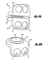
- the disc 10 includes an upper housing member generally shown at 12 and a lower housing member generally shown at 14.
- the housing members 12, 14 include spaced inner surfaces 16 and 18 facing each other and oppositely facing outer surfaces 20, 22 for engaging spaced apart vertebral surfaces.
- a pair of bearing surfaces 24, 26 extend from each of the inner surfaces 16, 18 for engaging each other while allowing for low friction and compression resistant movement of the housing members 12, 14 relative to each other while under compression.
- the bearing surfaces are integral with disc members 28, 30.
- the housing members 12, 14 can be made from various materials including metals, such as titanium, as well as ceramics, and plastics. Additionally, the housing members 12, 14 can be coated with materials to reduce friction between the components of the disc 10, specifically between the housing members 12, 14 and bearing disc members 28, 30.
- Coating materials include, but are not limited to, TiN (Titanium Nitride), diamond, diamond-like materials, synthetic carbon-based materials, chromium-based materials, and any other similar coating materials known to those of skill in the art. If integral with the bearing surfaces 24, 26, the housing members 12, 14 can be made from the preferred material for the bearing discs 28, 30 as discussed above. Based on this teaching, various other configurations can be made by those skilled in the art incorporating the present invention.
- the bearing surfaces 24, 26 preferably form a mobile bearing 23 that is capable of automatically adjusting the position of the bearing 23 within a housing 14 as needed.
- the mobile bearing 23 is shown in Figures 24 through 29.
- the bearing 23 is preferably made of any material that slides along the surface of the housing 14 in which it is placed, with minimal to no wear, on either the bearing 23 or the housing 14. Examples of such materials include ceramic, metal, or other suitable materials that do not negatively react with the housing 14.
- the bearing 23 of the present invention is disposed within a slot 35 of a housing 14.
- the bearing 23 is able to freely move or float within the slot 35 in response to movement of the housing 14.
- the bearing 23 is designed to provide proper cushioning and support of the housing 14 as is required by the specific system in which the bearing 23 is placed.
- the bearing 23 can be used in any joint for providing proper support of the joint. For example, if the bearing 23 is used in an artificial intervertebral disc assembly, the bearing 23 provides cushioning so as to prevent the plates that are housing the disc from touching and wearing on one another. When the bearing 23 is utilized within the knee, the bearing also provides cushioning for the housing 14 during movement of the housing 14.
- the bearing 23 disclosed herein can move freely under load conditions while maximizing the contact area of the upper and lower bearing surfaces 20, 24. In other words, within the slot 35 that the bearing 23 is disposed, the bearing 23 can move in any direction necessary to provide the proper support for the housing 14.
- the bearing 23 is able to move in this manner because the bearing 23 is a floating bearing, thus it is not attached or affixed to the housing 14 in which it is placed. Instead the bearing 23 "floats" within the housing 14, thus enabling the bearing 23 to be mobile and free to move in any direction necessary to provide proper support
- the housing 14 limits the "floating" motion of the bearing 23. In other words the movement of the bearing 23 can be limited based upon the size of the housing 14 arid more specifically the slot 35 in which the bearing 23 is disposed.
- the slot 35 in which the bearing 23 is disposed dictates the range of movement of the bearing 23, i.e. movement can be constrained such that the bearing 23 can only move from an anterior to a posterior position.
- the slot includes side walls 37, which define the size and shape of the slot 35, and a seat 39 on which the bearing is disposed.
- the movement of the bearing 23 is restricted based upon the shape of the walls 35 of the slot 35 in which the bearing 23 sits.
- the slot 35 can be in the shape of a circle, an oval, or any other round-sided shape.
- the slot 35 must be shaped to have rounded sides so as to prevent the bearing 23 from lodging in a corner of the slot 35.
- the slot 35 can be formed such that the seat 39 does not have a uniform depth, such that there are peaks or angles within the slot 35, as shown in Figure 27. The lack of uniformity restricts movement of the bearing 23 within the slot 35 because the bearing 23 would require additional force in order to slide in the direction of the peak or angle.
- a removable insert 33 is disposed within the housing 14 for holding the bearing 23 in place.
- the insert 33 includes an upper surface 29 for engaging the bearing surfaces 24, 26.
- the insert 33 can be made of any material that enables the bearing 23 to functionally "float" across the insert 33 without excessive friction.
- the benefit of including the insert 33 in a housing 14 is that the insert 33 can be made of a different material than that of the housing 14. Accordingly, the housing 14 can be made from a first composition that is advantageous for the functionality of the housing and provides other strength characteristics while the insert 33 can be made from a more lubricious material to allow for more efficient friction-free movement of the bearing 23 thereon.
- the movement of the bearing 23 is restricted based upon the shape of the insert 33 into which the bearing 23 is placed.
- the insert 33 includes side walls 41, which define the size and shape of the insert 33, and an insert seat 29 on which the bearing is disposed.
- the movement of the bearing 23 is restricted based upon the shape of the walls 41 of the insert 33 in which the bearing 23 sits.
- the insert 33 can be in the shape of a circle, an oval, or any other round-sided shape.
- the insert 33 must be shaped to have rounded sides so as to prevent the bearing 23 from lodging in a corner of the insert 33.
- the insert 33 can be formed such that the insert seat 29 does not have a uniform depth, such that there are peaks or angles within the insert 33, as shown in Figure 27. The lack of uniformity restricts movement of the bearing 23 within the insert 33 because the bearing 23 would require additional force in order to slide in the direction of the peak or angle.
- the housing 14 can also include load distributing dampening and cushioning pad recesses 32, 58.
- Load sharing pads 32, 34 generally shown at 31 and specifically indicated as pads 32 and 34 in Figures 1 and 2 are disposed between the inner surfaces 16, 18 and about at least a portion of the bearing surfaces 24, 26 for sharing absorption of compressive loads with the bearing surfaces 24, 26 while limiting relative movement of the housing members 12, 14. More specifically, under in vivo loading conditions, the centralized bearing surfaces 24, 26 and the floating bearing surfaces not only provide for three-dimensional movement relatively between the housing members 12, 14, but also share with the load sharing pads 32, 34 the function of distributing compressive loads on the device 10 to provide a system for motion and effective load distribution.
- the centralized low friction and compression resistant bearing surfaces 24, 26 allow full motion in multiple planes of the spine while the load distributing damper and cushioning pads 32, 34 simultaneously share the load.
- Critical is the function of the pads 32, 34 sharing the load with the bearing surfaces 24, 26.
- the pads 32, 34 can be compressible, the compression is limited by the noncompressibility of the bearing surfaces 24, 26.
- each element, the bearing surfaces 24, 26, and pads 32, 34 allow for movement, yet limit such movement, whether it is the sliding movement of the bearing surfaces 24, 26 or the cushioning movement allowed by the pads 32, 34.
- Each element allows for relative movement, yet each element limits the movement of the other element of the system.
- the system allows restoration of normal motion while maintaining load cushioning capabilities of a healthy disc. This is particularly apparent with motion of the spine. Any rotation of the upper and lower housing members 12, 14 causes the load distributing dampening and cushioning pads 32, 34 to absorb some of the load.
- the bearing surfaces 24, 26 can include a concave surface portion on one of the upper or lower disc members 28, 30, and a convex surface portion on the other.
- the concave surface is seated within the convex surface for sliding movement relative thereto effectively resulting in relative pivoting motion of the housing members 12, 14, which compresses at least a portion of the load sharing pads 32, 34 while extending at least a portion of the oppositely disposed load bearing pad 32, 34.
- either one of the top and bottom disc members 28, 30 can have either of the convex or concave surfaces.
- the disc members 28, 30 can be made from a composition that is noncompressible. Such compositions can be selected from the group including ceramics, plastics, and metal bearing materials, such as cobalt and chrome.
- the housing members 12, 14 can include projections wherein the disc members 28, 30 are effectively integral with the housing members 12, 14. In this situation, the entire housing, including the projections having the bearing surfaces 24, 26 thereon, can be made from the noncompressible material, preferably a ceramic.
- alternative configurations can be made by those skilled in the art once understanding the present invention.
- the load sharing pads 32, 34 can be in various configurations shown in the Figures, such as paired pads 32, 34 shown in Figures 1-3.
- the device 10 can include four oppositely disposed pads 38, 40, 42, 44 as shown in Figure 10.
- a further embodiment of the invention is shown in Figure 11, wherein a single pad 46 substantially covers the surface 18""' of the housing member 14""'.
- the pads can contour to the shape of the housing members such as shown in Figures 12, 13, wherein the pad member 48 is an annular pad member disposed with a annular housing 12""", 14""".
- housing members 12, 14 and pad members 31 can be determined based on the location of the placement of the device 10 as well as the spacing conditions between the vertebrae and load bearing necessities depending on the level of the spine being addressed.
- different shaped devices such as the round shaped housing members shown in Figure 12 can be used for placement between smaller discs, such as cervical spines whereas more rectangular shapes, such as the housing members shown in Figures 1-11 can be used in between lumbar vertebrae.
- the load sharing pads 31, in which ever shape they are configured, are elastic for allowing relative twisting movement between the housing members 12, 14 effecting relative three-dimensional movement between the housing members 12, 14, while limiting the movement and preventing contact between the housing members 12, 14 except for the contact between the bearing surfaces 24, 26.
- elastic it is meant that the pad members 31 are compressible and stretchable, yet provide a self-centering effect on the assembly with specific regard to the housing members 12, 14, as well as the bearing surfaces 24, 26. Deflection or rotation of the forces created due to relative movement of the bearing surfaces 24, 26, and likewise the housing members 12, 14, forces the pads 31 to act in such a way to counter the force, thus allowing a unique self-centering capability to the assembly 10.
- the pads 31 provide further advantages to the invention.
- a key advantage is the ability to adjust the pads 31 to patient and surgeon requirements. In such cases wherein range of motion needs to be restricted due to compromised facets, a harder, less elastic pad can be inserted between the housing members 12, 14. Since this less elastic pad would move and stretch less, the disc would be automatically restricted in motion.
- This method of adjusting pads can be done intraoperatively to compensate for surgical and patient conditions. To one skilled in the art, one can fine-tune the assembly 10 to a patient and surgeon's needs with multiple pads of different properties or materials.
- the pads 31 are made from a polymer or elastomer that allows deflection under load.
- examples of such polymers and elastomers are silicone, polyurethane, and urethane composites.
- the content and composition of the pads 31 are adjustable. A highly dense material creates a very rigid disc, while a very soft material creates a very free moving disc. The motion would be restricted in all planes of the pad depending upon these factors. Rotation is also restricted, as well as flexion or movement of the disc. The amount of compression possible is restricted or allowed according to the pads material properties. This is true of motion towards the back or side-to-side motion.
- the pads 31 are always in contact and always share the load, under any adjustment of relative positioning of the housing members 12, 14. Since motion forces the pads to be in contact, the pads 31 automatically damper loads imposed by the artificial disc construct 10.
- the pads can be selected from a composition having a durometer from 20 to 98 on the Shore OO Scale.
- the pads 31 can be selected from a composition having a durometer from 10 to 100 on the Shore A Scale.
- the pads 31 can be selected from a composition having a durometer from 22 to 75 on the Shore D Scale.
- the pad members 31 can be selected during the operation and procedure by the clinician to suit a specific situation.
- the various configurations of the present invention can allow for in situ replacement of the pad members 31 so as to custom select the flexibility or elasticity of the members. In this manner, the pad members 31 are custom designed for the individual environment of the intervertebral space into which the device is being disposed.
- the disc members 28 and 30, and pads 31 can be contained or locked in position in between the housing members 12, 14 by various means.
- the disc 28, 30 can be locked to the housing members 12, 14 by a press fit taper, retaining ring, or other means.
- the key aspect of such locking mechanisms is to prevent the disc members 28, 30 from moving against the upper or lower housing members 12, 14 once installed in order to prevent additional wear.
- FIGs 1 and 2 show disc members 28, 30 disposed in recesses (only the lower recess 50 is shown in Figure 2 in an exploded view) in each of the inner surfaces 16, 18 of the housing members 12, 14.
- Figures 6 and 7 show plan views of an example of the housing member 12', 14', wherein each recess 50', 52 includes a ramped surface 54, 56 leading from an outer edge to the inwardly tapered recess portion 50', 52.
- the ramping 54, 56 allows access of the disc members 28,30 in between the housing members 12', 14' after placement of the housing members 12', 14' in the intervertebral space.
- This intraoperative access of the disc members 28, 30 allows the surgeon to test different size disc members under load conditions to perfectly fit the disc members in place. Such an advantage is not obtainable with any prior art device.
- the representative housing member 12''' includes recess 52'.
- the recess 52' includes a substantially arcuate peripheral undergroove 70.
- the groove is defined by a lip portion 72 including at least one and preferably at least two openings 74, 76.
- the disc member 28"' includes bayonet style flanges 78, 80 extended radially outwardly therefrom, the flanges 78, 80 being shaped so as to be received through recess 74, 76.
- the disc member 28"' can be disposed within the recess 52' such that the flanges 78, 80 align with recesses 74, 76.
- the housing member 12''' includes a substantially arcuate recess 52" having an open end portion 82 extending to an edge 84 of the housing member 12"'.
- the recess 52" includes a lip portion 86 extending about a substantial portion thereof defining an inner groove 88 between the seating surface 90 of the recess 52" and the lip portion 86.
- Arm portions 92, 94 are extensions of the lip portion 86 but extend from and are separate from peripheral ends 96, 98 of the housing member 12"'.
- the arm portions 92, 94 have a spring-like quality such that they can be deflected outwardly from the arcuate circle defined by the recess 52".
- Each of the arms 92, 94 has an elbow portion 100, 102 extending from each arm portion 92, 94 towards the seating surface 90, respectively.
- the disc member 28''' includes a substantially arcuate peripheral, radially outwardly extending flange portion 104.
- the flange portion 104 includes two abutment edges 106, 108.
- the flange 104 and disc member 28''' are disposed within the annular recess or groove 88, deflecting outwardly the arms 92, 94.
- the elbows 100, 102 engage the abutment surfaces 106, 108 of the disc member 28''' thereby locking the disc member 28"' in place.
- Outward deflection of the arms 92, 94 can selectively release the disc member 28''' from locked engagement to provide for further adjustment of the selection of the disc member during an operation procedure.
- the pads members 31 can be disposed in recesses 58, 60 in the lower and upper housing members 12', 14' respectively. It is preferable to permanently adhere the pad members 31 to the housing members 12', 14' by use of mechanical mechanisms and/or various adhesives, such as cyanoarylates, urethanes, and other medical grade adhesives. This list of adhesives, as with other listings of ingredients in the present application, is merely exemplary and not meant to be exhaustive.
- Housing member 12" includes a central recess 52 such as shown in Figure 6 having a ramp portion 56.
- the ramp portion 56 includes a centrally located tongue groove 57 allowing for the insertion of a spatula type device under a disc member disposed within the recess 52 for releasing the disc member from the recess, similar to the use of a shoehorn type mechanism.
- Recesses 60' include undercut recesses 110, 112 for locking engagement with a peripheral flange portion 114 extending from an edge 116 of a pad member 31'.
- the flange portion 114 can be force-fit into and seated within the undercut 110, 112.
- the undercut locking mechanism effectively prevents the pad member 31' from disengagement with the housing member 12"" in situ.
- the upper flange 118 would be locked within a similar undercut locking detail of recesses within the opposing housing member (not shown).
- An alternative locking mechanism between the pad member and housing member can be a tongue-and-groove relationship as shown in Figure 23.
- Either the pad or the housing can include the tongue portion 122 and the other pad and housing members can include the groove 124.
- either of the locking members can include the tongue 122 and the other of the members being locked would include the groove 124.
- An alternative of this or the other locking mechanism shown is that the recess and/or pad can include multiple grooves or slots as well as multiple tongues.
- the various recesses or pockets 50', 52, 58, 60 can be of different relative sizes and shapes.
- the upper housing member 12' may have a larger recess or pocket for seating a relatively larger one of said discs 28 and the lower housing member 14' may be include a smaller (larger and smaller referring to diameter of the annular recess) of the recesses or pockets for seating a relatively smaller one of the lower disc 30, thereby providing for an increased range of motion at the bearing surface interface.
- the various Figures show that the outer surfaces 20, 22 of the various embodiments of the housing members 12, 14 can include flanges generally indicated at 60.
- the flanges 60 or fins as they are sometimes referred to in the art, provide a mechanism for fixation to the intervertebral surfaces.
- Various examples, such as those shown in Figures 1 and 2 are dual fin constructs.
- Other examples such as those shown in Figures 8, 12, and 13 are single fin or single flange constructs.
- the surgeon can select various flange or fin configurations.
- the fins 60 can be located in alternative positions, either centrally as shown in many of the Figures, or peripherally, as shown in Figure 14, for a specific use with anterior extension plates, as with screw fixations.
- the flanges, such as flange 60"""' can include a bore 62 therethrough, which can be either a smooth surface or threaded depending on its intended use.
- the outer surfaces 20, 22 can be smooth, which allows for easier revision as it allows for minimal to no ingrowth or they can be textured. Texturing of the outer surfaces 20, 22 allows ingrowth for long-term fixation of the assembly 10.
- Porous coatings, plasma spray, grit blasting, machining, chemical etching, or milling are examples of techniques for creating ingrowth capable surfaces. Coatings that enhance bone growth can also be applied. Examples of such coatings are hyroxyapatite and bone morphogenic proteins.
- Figures 20 and 21 provide structure for further rotational stability of the device in situ .
- the housing member 12"" includes pointed portions 126, 128 extending from the outer surface 20' thereof.
- the point members 126, 128 function in conjunction with the flange portion 61' to engage an opposing vertebral surface.
- the point portions 126, 128 being disposed radially peripherally from the centrally disposed flange 61' provide at least a three-point engagement of the vertebral surface thereby preventing rotation of the housing member 12"" relative thereto.
- the point portions 126, 128 can be in made in various configurations and extend various amounts from the outer surface 20' to be custom suited to a specific vertebrae surface shape.
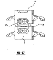
- the disc 10"""" can be formed as two separate pieces that are inserted into an intervertebral space, generally shown as 146 in Figure 30.
- the benefit of this formation of the disc 10""” is that the discs 10"""” can be inserted during a posterior insertion.
- the two discs 10""”” function so that the units work in tandem and effectively become one artificial disc assembly.
- the arrangement of the two discs 10"""” enables each disc 10"""” to be inserted on either side of the spinal column into the intervertebral space 146 and work in conjunction as a single artificial disc assembly 10"""".
- the two discs 10''''''''' are angled toward the mid-line of the vertebral body 146. While two disc assemblies 10"""" are described herein, more than two discs 10""" can also be utilized without departing from the spirit of the present invention.
- Each of the discs 10"""" include an upper housing member 12""” and a lower housing member 14"""".
- the housing members 12"""", 14"""” each include a slot 35' within the housing member 12""", 14"""".
- the slot 35' enables the bearing 23 to move freely or "float” within the slot 35' in response to movement of the housing 14.
- the slot 35' can be formed in any shape that enables proper movement of the bearing 23, however, preferably the slot 35' is an open-ended u-shaped slot with a seat 39' and side walls 37'. The side walls 37' maintain the bearing 23 in proper alignment within the housing 12"""", 14"""".
- the bearing 23 is capable of floating within the slot 35', thus enabling the bearing 23 to be mobile and free to move in any direction necessary to provide proper support for the housing 12"""", 14"""".
- the housing 12"""", 14""”” limits the motion of the bearing 23.
- the size of the housing 12""", 14"""" and, more specifically, the slot 35' in which the bearing 23 is disposed limits the motion of the bearing 23.
- bumpers 130, 132 can also be included in the slot 35' to further limit the motion of the bearing 23, provide dampening of the motion of the bearing 23 and prevent the bearing from being displaced from the housing 12"""", 14"""".
- the bumpers 130, 132 can be of any size sufficient to provide the necessary limitations on the bearing 23.
- each housing 12"""", 14""”” can incorporate separate bumpers 130,132.
- the bumpers 130,132 are also useful for load sharing and thereby preventing the housing members 12"""", 14"""” from contacting one another.
- the bumpers 130, 132 are shaped to conform to the shape of the slot 35'. In other words, the bumpers 130, 132 are shaped to precisely fit the slot 35' in which the bumpers 103, 132 are displaced.
- the bumpers 130, 132 do not extend beyond the length of the housing 12""", 14"""".
- the bumpers 130, 132 have walls 134, 136 respectively that engage the wall 37' of the slot 35'. This enables the bumpers 130, 132 to be maintained in alignment and prevents the bumpers 130, 132 from moving.
- the upper housing 12"""” can either include a slot 35' identical to that of the lower housing 14""”” or can include a single piece having a matching bearing that complements that of the bearing 23.
- the upper housing 12"""” can either have a slot 35' that is identical to the shape of the slot 35' of the lower housing 14"""", such that the bearing 23 moves both in both housings 12"""", 14"""" equally or the upper housing 12""”” can be formed such that only a single piece is utilized and there is no movement within the top plate of the bearing 23.
- the bearing 23' includes side arms 138, 140 that slidably engaged the wall 37' of the slot 35'. The bearing 23' is therefore held in position within the slot 35' via the side arms 138, 140 and the bumpers 130, 132.
- the bearing 23 can also have incorporated on the bearing surface 24 various shapes as shown in the figures.
- Figure 32 shows the bearing surface 24', wherein the surface 24' is a spherical surface.
- the spherical surface 24' enables the center of rotation of the bearing 23' to exist at the center of the sphere. Therefore, the pair of discs 10"""" functions as a single artificial disc with one center of rotation.
- the bearing 23 can have a surface that is either convex 24" or concave 24"'.
- This embodiment is specifically shown in Figures 9 and 10 wherein the center portion of the bearing 23' is either convex or concave and there is a flat portion 29 of the bearing 23'.
- a convex or concave surface 24", 24''' respectively is utilized, the rotation center is not in the center for side-to-side rotation.
- the assembly is somewhat resistant to side-to-side bending but is more easily aligned.
- the housings 12"""", 14""”” can be inserted simultaneously without incorporating the floating bearing 23 initially. This enables the disc 10"""” to be inserted into the intervertebral space and once the disc 10"""” has been inserted, the bumpers 130, 132 and the bearing 23 can be slid into place within the slot 35'.
- the lower housing member 12''''''''' and the upper housing member 14"""' include a recess 52"' for seating a positioning ring 15, or spring mechanism 15, and bearing discs 28"", 30"" therein (See, Figures 41 and 42).
- the recess 52''' includes a substantially arcuate peripheral undergroove 70" or wall 70" and a bottom surface 19 that can be super finished smooth.
- the recess 52''' accommodates the positioning ring 15 therein and the undergroove 70" secures the positioning ring 15.
- the undergroove 70" is defined by a lip portion 72".
- the housings 12"""', 14"""' include at least one aperture 17 for insertion of screws therein and to secure the housings 12""""', 14""""' to a vertebral body.
- the positioning ring 15 can be fixedly or removably attached to the housings 12"""', 14""""'.
- the bearing discs 28"", 30"" can be fixedly or removably attached to the housings 12"""', 14""""'.
- the positioning ring 15, or spring member 15, is elastomeric and can be made any material including, but not limited to, rubber, silicone, polyurethane, urethane composites, plastics, polymers, elastomers, and any other similar elastomeric material known to those of skill in the art.
- the positioning ring 15 is illustrated in detail in Figures 41 - 46.
- the positioning ring 15 or spring member 15 is a substantially annular body including an axially extended bore therethrough defining a passageway.
- the positioning ring is circular in shape, any similar or appropriate design can be used such as an oval shape.
- the substantially annular body has a seat extending radially inward towards the bore for seating therein the bearing discs 28, 30 and has an engaging member extending radially outward from the bore for engaging the recess 52 of the housing member 12, 14 and securing the positioning ring within the recess 52.
- the engaging member can be any portion of the substantially annular body that radially extends from the bore.
- the engaging member includes, but is not limited to, a tapered edge, flange, and the like. The engaging member is shaped so as to be received by the recess and the recess securely engages the engaging member resulting in securing the positioning ring within the recess.
- the purpose of the positioning ring 15 or spring member 15 is to absorb compressive loads between the bearing discs 28, 30 and the undergroove 70" or wall" of the recess of the housing member, while controlling motion and position of the bearing discs 28, 30.
- the positioning ring 15 cushions and provides bias to absorb compression and lateral forces, while acting as a spring to re-center the bearing discs 28, 30 after being displaced through vertebral function.
- the bearing discs 28"", 30"" are situated within the opening of the positioning ring 15 or spring mechanism 15.
- the bearing discs 28"", 30"” can move within the positioning ring 15 and thus the housings 12""""', 14""""' therein. However, movement within the housings 12""""', 14""""' is semi-constrained by the positioning ring 15.
- the positioning ring acts as a spring to self-center the bearing discs 28"", 30"" and as a shock absorption member.
- the positioning ring 15 acts as a damper and self-centering spring. Therefore, the bearing can translate in any direction, while the positioning ring exerts a force to push the bearing back to center.
- the bearing discs 28""', 30""' along with the positioning ring 15' are oval shaped.
- the recess 52"" located on each housing member 12"""", 14""""” is oval-shaped, while the housing members 12, 14 can also be oval shaped, circular, or any other suitable shape known to those of skill in the art.
- the recess 52"" accommodates the positioning ring 15' therein and an undergroove 70"' secures the positioning ring 15'.
- the undergroove 70"' is defined by a lip portion 72"'.
- the bearing discs 28""', 30""' can be fixed within the oval recess 52"' or the bearing discs 28""', 30""' can be floating (i.e., mobile bearing discs) within the oval recess 52''' of the housing members 12""""", 14""""".
- the bearing discs 28""', 30""' have oval circumferential exterior sides 21 and a spherical surface machined into the bearing surface 24, 26.
- Figure 44 illustrates the approximate shape of the positioning ring 15'.
- Figure 45 shows the positioning ring 15' in place within the recess 52"" and illustrates the oval shape in greater detail.
- Figure 46 illustrates an upper housing member 14"""", wherein the bearing disc 30""' is fixed onto the upper housing member 14""""".
- the exterior circumference of the bearing discs is oval, with the bearing surface 24, 26 being spherical.
- positioning ring 15' engages the oval circumferential exterior sides 21 of the bearing discs 28""', 30""' and the undergroove 70"' of the recess 52"" of the housing members 12""""", 14"””"".
- the positioning ring 15' acts as a spring counteracting the rotational forces to allow rotation, while preventing excess rotation therefrom.
- the positioning ring 15' can be changed in durometer to create more motion or less motion by altering the effective spring rate of the material.
- patient specific positioning rings 15' can be chosen based on patient requirements. In cases where facet joints are deteriorated, the disc 10 can compensate by using a higher durometer positioning ring 15' and allowing the surgeon full optimization at the time of surgery.
- the positioning ring 15' acts as a spring to resist excessive motion, while acting as a spring to self-center the disc construct As shown in Figures, the oval aspect allows the necessary engagement area to permit the combination of benefits. Also, by using such an oval surface, the positioning ring 15' remains in compression at all times, allowing maximum benefit and performance from various polymers.
- the oval recess 52"" could be any elongated surface that effectively provides some moment arm to exert force on the positioning ring 15'.
- an assembled device 10 as shown in Figure 1 can be disposed between the intervertebral spaces during surgery, after calculation of space, depth, and height.
- opposing housing members 12, 14 can be disposed between the intervertebral spaces and pads 31 and disc members 24, 26 can be tested in situ prior to fixation thereof to allow for custom sizing.
- the present invention broadly provides a method of assembling an artificial intervertebral disc 10 in vivo by inserting upper and lower housing members 12, 14 into an intervertebral space and disposing cushioning pads 31 between the inner surfaces 16, 18 of the housing members 12, 14, thereby placing the pads in compression.
- the pair of disc members 28, 30 is inserted between the inner surfaces of the plates 16, 18.
- the disc members 28, 30 have abutting low friction surfaces 24, 26 therebetween.
- the disc members 28, 30 are surrounded by the pads 31, whereby the disc members 28, 30 and pads 31 are under compressive forces and share such compressive forces. This step of the bearing surfaces 24, 26 and shock absorbing pads 31 sharing absorption of the compressive forces and limiting the relative movement of the housing members 12, 14 is an advantage not found in the prior art.
- the bearing of the present invention is in an artificial intervertebral disc for replacement of a damaged disc in the spine.
- the artificial disc 10 of the present application includes a mobile bearing 23 that allows for the bearing 23 to move to adjust and compensate for vertebral disc motion. By permitting the bearing to self-adjust, the bearing 23 can more freely move under translation loading conditions while maximizing the contact area of the upper and lower bearing surfaces 20, 24.
- the disc upper member and lower member are angled relative to each other to maintain spinal curvature.
- the load distributing damper and cushioning pads are always under some load when the spine is moving, although they can be adjusted for a neutral no load situation when the spine is not moving.
- the load distributing damper and cushioning pads also create an elastic means of self-centering the disc construct. Deflection of rotation of the disc forces the pads to act in such a way as to counter the force, thus allowing a unique self-centering capability. In an ideal situation where the patient's facets are uncompromised and ligamental balance is intact, this is not necessary. However, ligamental balance and damaged facets would normally make an artificial disc questionable at best with the current art In such cases, having the ability to self-center and restrict motion (the pads are elastic and thus restrict motion by stretching and returning to rest), the possibilities of extending indications to patients currently considered outside the scope of artificial disc technology is highly advantageous. In a floating bearing design, the ability to self-center mixed with the dampening abilities of the pads creates an ideal system for an artificial disc.
- the pads can also be adjusted according to patient and surgeon requirements. In such cases where range of motion needs to be restricted due to compromised facets, a harder, less elastic pad can be inserted. Since a less elastic pad moves and stretches less, the disc is automatically restricted in motion. This method of adjusting pads can be done interoperatively to compensate for surgical and patient conditions.
- any of the above embodiments can be used in a cervical disc surgical procedure.
- the general procedure begins with the removal of the damaged disc ( Figures 49-57 illustrate the procedure).
- a trial handle is attached to the trial and the trial is inserted into the disc space ( Figure 49).
- the trial is adjusted until the disc height is approximately restored, while being careful not to overstretch the ligaments.
- pilot holes are drilled at the four guide plate hole locations ( Figure 50).
- the guide plate is secured with self-tapping guide plate screws ( Figure 51).
- reaming disks are inserted to match the trial number.
- the depth of the instrument on the dial to the matching number must then be set Once set, the instrument is advanced into the disc space with the button engaged (Figure 52). The fins on the instrument remain engaged in the slot on the guide plate for stability. Once maximum depth is reached, the end plate preparation instrument is removed ( Figure 53). The guide plate screws and guide plate are then removed ( Figure 54). The disc holder with holes in plate aligned with holes in the vertebrae is inserted until fully seated ( Figure 55). Screws are then inserted into threaded holes to secure disc to the vertebral bodies ( Figure 56). Finally, the disc inserter is removed ( Figure 57).
Landscapes
- Health & Medical Sciences (AREA)
- Engineering & Computer Science (AREA)
- Biomedical Technology (AREA)
- Neurology (AREA)
- Orthopedic Medicine & Surgery (AREA)
- Heart & Thoracic Surgery (AREA)
- Oral & Maxillofacial Surgery (AREA)
- Transplantation (AREA)
- Cardiology (AREA)
- Vascular Medicine (AREA)
- Life Sciences & Earth Sciences (AREA)
- Animal Behavior & Ethology (AREA)
- General Health & Medical Sciences (AREA)
- Public Health (AREA)
- Veterinary Medicine (AREA)
- Prostheses (AREA)
- Magnetic Bearings And Hydrostatic Bearings (AREA)
Claims (11)
- Künstliche Bandscheibe (10), umfassend:Gehäuseglieder (12, 14) mit voneinander beabstandeten, einander zugewandten Innenflächen (16, 18) und in entgegengesetzte Richtung weisenden Außenflächen (20, 22) zum Eingriff in voneinander beabstandete intervertebrale Flächen;selbsteinstellende Lagermittel (23), wirksam angeordnet zwischen den Innenflächen (16, 18) für eine Bewegung relativ zu den Gehäusegliedern (12, 14) zum Einstellen und Kompensieren von Bandscheibenbewegung; undPositionierringmittel (33) zum Kontrollieren von Bewegung und Position der Lagermittel und zur Absorption von Druckbelastungen, dadurch gekennzeichnet, dass die Innenflächen (16, 18) mindestens eine Ausnehmung (52) innerhalb jeder der Innenflächen aufweisen zum Lagern der Positionierringmittel in derselben, wobei die Ausnehmung (52) eine Unternut (70) aufweist und wobei die Positionierringmittel (33) Eingriffsmittel umfassen, welche mit der Unternut (70) in Wirkeingriff stehen.
- Künstliche Bandscheibe nach Anspruch 1, wobei die Positionierringmittel (33) in sicherem Eingriff mit den selbsteinstellenden Lagermitteln (23) stehen und Bewegung der Lagermittel (23) erlauben.
- Künstliche Bandscheibe nach Anspruch 1 oder Anspruch 2, wobei die Gehäuseglieder (12, 14) aus einer Zusammensetzung konstruiert sind, die ausgewählt ist aus der Gruppe, welche im Wesentlichen aus Metallen, Keramiken und Kunststoffen besteht.
- Künstliche Bandscheibe nach einem der voranstehenden Ansprüche, wobei die Gehäuseglieder (12, 14) eine Außenfläche (20, 22) mit einer Beschichtung hierauf aufweisen.
- Künstliche Bandscheibe nach Anspruch 4, wobei die Beschichtung ausgewählt ist aus TiN (Titannitrid), Diamant, diamantartigen Materialien, synthetischen kohlenstoffbasierten Materialien und chrombasierten Materialien.
- Künstliche Bandscheibe nach einem der voranstehenden Ansprüche, wobei die Lagermittel (23) aus einer Zusammensetzung konstruiert sind, die ausgewählt ist aus Metallen, Keramiken und Kunststoffen.
- Künstliche Bandscheibe nach einem der voranstehenden Ansprüche, wobei die Positionierringmittel (33) aus Materialien hergestellt sind, die ausgewählt sind aus Gummi, Silicon, Polyurethan, Urethan-Kompositen, Kunststoffen, Polymeren und Elastomeren.
- Künstliche Bandscheibe nach einem der voranstehenden Ansprüche, wobei die Gehäuseglieder (12, 14) mindestens eine Öffnung aufweisen zum Aufnehmen von mindestens einer Knochenschraube.
- Künstliche Bandscheibe nach Anspruch 1, wobei die Innenflächen (16, 18) eine ovale Ausnehmung (52) hierauf aufweisen;
wobei die Lagermittel (28, 30) wirksam angeordnet sind innerhalb der ovalen Ausnehmung (52) zwischen den Innenflächen (16, 18); und
wobei die Positioniermittel (15) Federmittel in Wirkeingriff zwischen der Ausnehmung (52) und den Lagermitteln (28, 30) zum Absorbieren von Stoß und zum Selbstzentrieren der Lagermittel (28, 30) sind. - Künstliche Bandscheibe nach Anspruch 1, wobei die Innenflächen (16, 18) eine ovale Ausnehmung (52) hierauf aufweisen;
wobei die Lagermittel (28, 30) oval sind und wirksam angeordnet sind innerhalb der ovalen Ausnehmung (52) zwischen den Innenflächen (16, 18); und
wobei die Positionierringmittel (15) oval sind und in Wirkeingriff stehen mit der ovalen Ausnehmung (52) und den ovalen Lagermitteln (28, 30) zum Kontrollieren von Bewegung und Position der Lagermittel (28, 30) und zur Absorption von Druckbelastungen zwischen den Lagermitteln (28, 30) und den Gehäusegliedern (12, 14). - Federglied (15) für eine künstliche Bandscheibe (10), umfassend:einen im Wesentlichen ringförmigen Körper mit einer axial verlaufenden Bohrung durch denselben hindurch, welche einen Durchgang definiert;sich radial einwärts in Richtung zu der Bohrung hin erstreckende Sitzmittel zum Lagern von Lagermitteln in denselben zum Einstellen und Kompensieren von Bandscheibenbewegung; undsich radial auswärts von der Bohrung erstreckende Eingriffsmittel zum Eingriff in ein Gehäuseglied (12, 14) und zum Sichern des Federglieds (15) innerhalb des Gehäuseglieds (12, 14), wobei das Federglied (15) Druckbelastungen zwischen den Lagermitteln (28, 30) und dem Gehäuseglied (12, 14) absorbiert, während es Bewegung und Position der Lagermittel (28, 30) kontrolliert, dadurch gekennzeichnet, dassdie Eingriffsmittel zum Eingriff mit einer Unternut (70) einer an dem Gehäuseglied (12) befindlichen Ausnehmung (52) ausgebildet sind.
Applications Claiming Priority (4)
| Application Number | Priority Date | Filing Date | Title |
|---|---|---|---|
| US10/430,861 US7105024B2 (en) | 2003-05-06 | 2003-05-06 | Artificial intervertebral disc |
| US10/653,540 US20040225363A1 (en) | 2003-05-06 | 2003-09-02 | Artificial intervertebral disc |
| US700748 | 2003-11-03 | ||
| US10/700,748 US7291173B2 (en) | 2003-05-06 | 2003-11-03 | Artificial intervertebral disc |
Publications (2)
| Publication Number | Publication Date |
|---|---|
| EP1527759A1 EP1527759A1 (de) | 2005-05-04 |
| EP1527759B1 true EP1527759B1 (de) | 2007-01-03 |
Family
ID=46205337
Family Applications (2)
| Application Number | Title | Priority Date | Filing Date |
|---|---|---|---|
| EP04255310A Withdrawn EP1514527A3 (de) | 2003-05-06 | 2004-09-02 | Künstliche Bandscheibe |
| EP04256781A Expired - Lifetime EP1527759B1 (de) | 2003-05-06 | 2004-11-03 | Künstliche Bandscheibe |
Family Applications Before (1)
| Application Number | Title | Priority Date | Filing Date |
|---|---|---|---|
| EP04255310A Withdrawn EP1514527A3 (de) | 2003-05-06 | 2004-09-02 | Künstliche Bandscheibe |
Country Status (7)
| Country | Link |
|---|---|
| EP (2) | EP1514527A3 (de) |
| JP (1) | JP2005137905A (de) |
| AT (1) | ATE349983T1 (de) |
| AU (1) | AU2004224985B2 (de) |
| CA (1) | CA2486623C (de) |
| DE (1) | DE602004004030T2 (de) |
| ES (1) | ES2280011T3 (de) |
Cited By (1)
| Publication number | Priority date | Publication date | Assignee | Title |
|---|---|---|---|---|
| US8715352B2 (en) | 2006-12-14 | 2014-05-06 | Depuy Spine, Inc. | Buckling disc replacement |
Families Citing this family (10)
| Publication number | Priority date | Publication date | Assignee | Title |
|---|---|---|---|---|
| US7105024B2 (en) | 2003-05-06 | 2006-09-12 | Aesculap Ii, Inc. | Artificial intervertebral disc |
| US7291173B2 (en) | 2003-05-06 | 2007-11-06 | Aesculap Ii, Inc. | Artificial intervertebral disc |
| EP1755500A4 (de) * | 2004-06-15 | 2012-02-22 | Aesculap Implant Systems Inc | Künstliche bandscheibe |
| US8137404B2 (en) | 2006-03-28 | 2012-03-20 | Depuy Spine, Inc. | Artificial disc replacement using posterior approach |
| US8282641B2 (en) | 2006-03-28 | 2012-10-09 | Depuy Spine, Inc. | Methods and instrumentation for disc replacement |
| CA2675222A1 (en) | 2007-01-12 | 2008-07-24 | Synthes Usa, Llc | Modular intervertebral implant |
| US20090270988A1 (en) * | 2008-04-24 | 2009-10-29 | Ranier Limited | Artificial spinal disc implant |
| WO2012005961A1 (en) | 2010-06-28 | 2012-01-12 | Synthes Usa, Llc | Coated implant |
| CA3119918A1 (en) | 2011-03-09 | 2012-09-13 | Regents Of The University Of Minnesota | Compositions and methods for transplantation of colon microbiota |
| DE102013005398B3 (de) * | 2013-03-28 | 2014-06-18 | Spontech Spine Intelligence Group Ag | Bewegungserhaltende Bandscheibenprothese |
Family Cites Families (19)
| Publication number | Priority date | Publication date | Assignee | Title |
|---|---|---|---|---|
| CA1283501C (en) * | 1987-02-12 | 1991-04-30 | Thomas P. Hedman | Artificial spinal disc |
| DE9000094U1 (de) * | 1990-01-04 | 1991-01-31 | Mecron Medizinische Produkte Gmbh, 1000 Berlin | Endoprothese der Zwischenwirbelscheibe |
| FR2659226B1 (fr) * | 1990-03-07 | 1992-05-29 | Jbs Sa | Prothese pour disques intervertebraux et ses instruments d'implantation. |
| US5425773A (en) * | 1992-01-06 | 1995-06-20 | Danek Medical, Inc. | Intervertebral disk arthroplasty device |
| DE4208116C2 (de) * | 1992-03-13 | 1995-08-03 | Link Waldemar Gmbh Co | Bandscheibenendoprothese |
| FR2694882B1 (fr) * | 1992-08-24 | 1994-10-21 | Sofamor | Prothèse discale intervertébrale. |
| US5676701A (en) * | 1993-01-14 | 1997-10-14 | Smith & Nephew, Inc. | Low wear artificial spinal disc |
| FR2718635B1 (fr) * | 1994-04-15 | 1996-07-05 | Axcyl Medical | Prothèse cervicale. |
| US5674296A (en) * | 1994-11-14 | 1997-10-07 | Spinal Dynamics Corporation | Human spinal disc prosthesis |
| US5782832A (en) * | 1996-10-01 | 1998-07-21 | Surgical Dynamics, Inc. | Spinal fusion implant and method of insertion thereof |
| WO1999005995A1 (en) * | 1997-08-04 | 1999-02-11 | Gordon, Maya, Roberts & Thomas Number 1 Llc | Multiple axis intervertebral prosthesis |
| US6146421A (en) * | 1997-08-04 | 2000-11-14 | Gordon, Maya, Roberts And Thomas, Number 1, Llc | Multiple axis intervertebral prosthesis |
| US5888226A (en) * | 1997-11-12 | 1999-03-30 | Rogozinski; Chaim | Intervertebral prosthetic disc |
| FR2787017B1 (fr) * | 1998-12-11 | 2001-04-27 | Dimso Sa | Prothese de disque intervertebral a comportement mecanique ameliore |
| NZ516410A (en) * | 1999-07-02 | 2004-12-24 | Spine Solutions Inc | Intervertebral implant |
| CA2392868C (fr) * | 1999-12-01 | 2008-08-05 | Henry Graf | Dispositif de stabilisation intervertebral |
| FR2805985B1 (fr) * | 2000-03-10 | 2003-02-07 | Eurosurgical | Prothese de disque intervertebral |
| ES2286171T3 (es) * | 2002-03-12 | 2007-12-01 | Cervitech, Inc. | Protesis intervertebral, especialmente para la columna cervical. |
| US6793678B2 (en) * | 2002-06-27 | 2004-09-21 | Depuy Acromed, Inc. | Prosthetic intervertebral motion disc having dampening |
-
2004
- 2004-09-02 EP EP04255310A patent/EP1514527A3/de not_active Withdrawn
- 2004-11-03 AT AT04256781T patent/ATE349983T1/de active
- 2004-11-03 AU AU2004224985A patent/AU2004224985B2/en not_active Expired - Fee Related
- 2004-11-03 CA CA2486623A patent/CA2486623C/en not_active Expired - Fee Related
- 2004-11-03 EP EP04256781A patent/EP1527759B1/de not_active Expired - Lifetime
- 2004-11-03 ES ES04256781T patent/ES2280011T3/es not_active Expired - Lifetime
- 2004-11-03 DE DE602004004030T patent/DE602004004030T2/de not_active Expired - Lifetime
- 2004-11-04 JP JP2004321363A patent/JP2005137905A/ja active Pending
Cited By (1)
| Publication number | Priority date | Publication date | Assignee | Title |
|---|---|---|---|---|
| US8715352B2 (en) | 2006-12-14 | 2014-05-06 | Depuy Spine, Inc. | Buckling disc replacement |
Also Published As
| Publication number | Publication date |
|---|---|
| ES2280011T3 (es) | 2007-09-01 |
| EP1514527A3 (de) | 2005-10-26 |
| EP1527759A1 (de) | 2005-05-04 |
| AU2004224985B2 (en) | 2009-05-07 |
| DE602004004030T2 (de) | 2007-11-15 |
| AU2004224985A1 (en) | 2005-05-19 |
| EP1514527A2 (de) | 2005-03-16 |
| CA2486623C (en) | 2011-02-22 |
| ATE349983T1 (de) | 2007-01-15 |
| DE602004004030D1 (de) | 2007-02-15 |
| JP2005137905A (ja) | 2005-06-02 |
| CA2486623A1 (en) | 2005-05-03 |
Similar Documents
| Publication | Publication Date | Title |
|---|---|---|
| US7832409B2 (en) | Method of inserting an artificial intervertebral disc | |
| US20050143824A1 (en) | Artificial intervertebral disc | |
| US7766966B2 (en) | Artificial intervertebral disc | |
| CN101022770B (zh) | 人造脊椎盘 | |
| US8167948B2 (en) | Anterior prosthetic spinal disc replacement | |
| US8216314B2 (en) | Distractable spinal implant assembly | |
| EP1691730A2 (de) | Halbeingezwängte bandscheibenprothese mit mobilem lager | |
| EP1527759B1 (de) | Künstliche Bandscheibe | |
| EP2258322A2 (de) | Künstliche Bandscheibe | |
| JP4695717B2 (ja) | 人工椎間板 | |
| EP1755500A1 (de) | Künstliche bandscheibe |
Legal Events
| Date | Code | Title | Description |
|---|---|---|---|
| PUAI | Public reference made under article 153(3) epc to a published international application that has entered the european phase |
Free format text: ORIGINAL CODE: 0009012 |
|
| AK | Designated contracting states |
Kind code of ref document: A1 Designated state(s): AT BE BG CH CY CZ DE DK EE ES FI FR GB GR HU IE IS IT LI LU MC NL PL PT RO SE SI SK TR |
|
| AX | Request for extension of the european patent |
Extension state: AL HR LT LV MK YU |
|
| 17P | Request for examination filed |
Effective date: 20051031 |
|
| AKX | Designation fees paid |
Designated state(s): AT BE BG CH CY CZ DE DK EE ES FI FR GB GR HU IE IS IT LI LU MC NL PL PT RO SE SI SK TR |
|
| RAP1 | Party data changed (applicant data changed or rights of an application transferred) |
Owner name: AESCULAP II, INC. |
|
| GRAP | Despatch of communication of intention to grant a patent |
Free format text: ORIGINAL CODE: EPIDOSNIGR1 |
|
| GRAS | Grant fee paid |
Free format text: ORIGINAL CODE: EPIDOSNIGR3 |
|
| GRAA | (expected) grant |
Free format text: ORIGINAL CODE: 0009210 |
|
| AK | Designated contracting states |
Kind code of ref document: B1 Designated state(s): AT BE BG CH CY CZ DE DK EE ES FI FR GB GR HU IE IS IT LI LU MC NL PL PT RO SE SI SK TR |
|
| PG25 | Lapsed in a contracting state [announced via postgrant information from national office to epo] |
Ref country code: FI Free format text: LAPSE BECAUSE OF FAILURE TO SUBMIT A TRANSLATION OF THE DESCRIPTION OR TO PAY THE FEE WITHIN THE PRESCRIBED TIME-LIMIT Effective date: 20070103 Ref country code: SI Free format text: LAPSE BECAUSE OF FAILURE TO SUBMIT A TRANSLATION OF THE DESCRIPTION OR TO PAY THE FEE WITHIN THE PRESCRIBED TIME-LIMIT Effective date: 20070103 Ref country code: PL Free format text: LAPSE BECAUSE OF FAILURE TO SUBMIT A TRANSLATION OF THE DESCRIPTION OR TO PAY THE FEE WITHIN THE PRESCRIBED TIME-LIMIT Effective date: 20070103 Ref country code: NL Free format text: LAPSE BECAUSE OF FAILURE TO SUBMIT A TRANSLATION OF THE DESCRIPTION OR TO PAY THE FEE WITHIN THE PRESCRIBED TIME-LIMIT Effective date: 20070103 Ref country code: DK Free format text: LAPSE BECAUSE OF FAILURE TO SUBMIT A TRANSLATION OF THE DESCRIPTION OR TO PAY THE FEE WITHIN THE PRESCRIBED TIME-LIMIT Effective date: 20070103 |
|
| REG | Reference to a national code |
Ref country code: GB Ref legal event code: FG4D |
|
| RAP2 | Party data changed (patent owner data changed or rights of a patent transferred) |
Owner name: AESCULAP IMPLANT SYSTEMS, INC. |
|
| REF | Corresponds to: |
Ref document number: 602004004030 Country of ref document: DE Date of ref document: 20070215 Kind code of ref document: P |
|
| REG | Reference to a national code |
Ref country code: IE Ref legal event code: FG4D |
|
| NLT2 | Nl: modifications (of names), taken from the european patent patent bulletin |
Owner name: AESCULAP IMPLANT SYSTEMS, INC. Effective date: 20070117 |
|
| PG25 | Lapsed in a contracting state [announced via postgrant information from national office to epo] |
Ref country code: SE Free format text: LAPSE BECAUSE OF FAILURE TO SUBMIT A TRANSLATION OF THE DESCRIPTION OR TO PAY THE FEE WITHIN THE PRESCRIBED TIME-LIMIT Effective date: 20070403 |
|
| PG25 | Lapsed in a contracting state [announced via postgrant information from national office to epo] |
Ref country code: BG Free format text: LAPSE BECAUSE OF FAILURE TO SUBMIT A TRANSLATION OF THE DESCRIPTION OR TO PAY THE FEE WITHIN THE PRESCRIBED TIME-LIMIT Effective date: 20070404 |
|
| REG | Reference to a national code |
Ref country code: CH Ref legal event code: NV Representative=s name: E. BLUM & CO. AG PATENT- UND MARKENANWAELTE VSP |
|
| PG25 | Lapsed in a contracting state [announced via postgrant information from national office to epo] |
Ref country code: IS Free format text: LAPSE BECAUSE OF FAILURE TO SUBMIT A TRANSLATION OF THE DESCRIPTION OR TO PAY THE FEE WITHIN THE PRESCRIBED TIME-LIMIT Effective date: 20070503 |
|
| PG25 | Lapsed in a contracting state [announced via postgrant information from national office to epo] |
Ref country code: PT Free format text: LAPSE BECAUSE OF FAILURE TO SUBMIT A TRANSLATION OF THE DESCRIPTION OR TO PAY THE FEE WITHIN THE PRESCRIBED TIME-LIMIT Effective date: 20070604 |
|
| NLV1 | Nl: lapsed or annulled due to failure to fulfill the requirements of art. 29p and 29m of the patents act | ||
| ET | Fr: translation filed | ||
| REG | Reference to a national code |
Ref country code: ES Ref legal event code: FG2A Ref document number: 2280011 Country of ref document: ES Kind code of ref document: T3 |
|
| PLBE | No opposition filed within time limit |
Free format text: ORIGINAL CODE: 0009261 |
|
| STAA | Information on the status of an ep patent application or granted ep patent |
Free format text: STATUS: NO OPPOSITION FILED WITHIN TIME LIMIT |
|
| PG25 | Lapsed in a contracting state [announced via postgrant information from national office to epo] |
Ref country code: SK Free format text: LAPSE BECAUSE OF FAILURE TO SUBMIT A TRANSLATION OF THE DESCRIPTION OR TO PAY THE FEE WITHIN THE PRESCRIBED TIME-LIMIT Effective date: 20070103 |
|
| 26N | No opposition filed |
Effective date: 20071005 |
|
| PG25 | Lapsed in a contracting state [announced via postgrant information from national office to epo] |
Ref country code: BE Free format text: LAPSE BECAUSE OF FAILURE TO SUBMIT A TRANSLATION OF THE DESCRIPTION OR TO PAY THE FEE WITHIN THE PRESCRIBED TIME-LIMIT Effective date: 20070103 Ref country code: RO Free format text: LAPSE BECAUSE OF FAILURE TO SUBMIT A TRANSLATION OF THE DESCRIPTION OR TO PAY THE FEE WITHIN THE PRESCRIBED TIME-LIMIT Effective date: 20070103 Ref country code: CZ Free format text: LAPSE BECAUSE OF FAILURE TO SUBMIT A TRANSLATION OF THE DESCRIPTION OR TO PAY THE FEE WITHIN THE PRESCRIBED TIME-LIMIT Effective date: 20070103 |
|
| PG25 | Lapsed in a contracting state [announced via postgrant information from national office to epo] |
Ref country code: GR Free format text: LAPSE BECAUSE OF FAILURE TO SUBMIT A TRANSLATION OF THE DESCRIPTION OR TO PAY THE FEE WITHIN THE PRESCRIBED TIME-LIMIT Effective date: 20070404 |
|
| PGFP | Annual fee paid to national office [announced via postgrant information from national office to epo] |
Ref country code: IE Payment date: 20080128 Year of fee payment: 4 |
|
| REG | Reference to a national code |
Ref country code: FR Ref legal event code: CD |
|
| PG25 | Lapsed in a contracting state [announced via postgrant information from national office to epo] |
Ref country code: MC Free format text: LAPSE BECAUSE OF NON-PAYMENT OF DUE FEES Effective date: 20071130 |
|
| PG25 | Lapsed in a contracting state [announced via postgrant information from national office to epo] |
Ref country code: EE Free format text: LAPSE BECAUSE OF FAILURE TO SUBMIT A TRANSLATION OF THE DESCRIPTION OR TO PAY THE FEE WITHIN THE PRESCRIBED TIME-LIMIT Effective date: 20070103 |
|
| PG25 | Lapsed in a contracting state [announced via postgrant information from national office to epo] |
Ref country code: CY Free format text: LAPSE BECAUSE OF FAILURE TO SUBMIT A TRANSLATION OF THE DESCRIPTION OR TO PAY THE FEE WITHIN THE PRESCRIBED TIME-LIMIT Effective date: 20070103 |
|
| PG25 | Lapsed in a contracting state [announced via postgrant information from national office to epo] |
Ref country code: LU Free format text: LAPSE BECAUSE OF NON-PAYMENT OF DUE FEES Effective date: 20071103 |
|
| PG25 | Lapsed in a contracting state [announced via postgrant information from national office to epo] |
Ref country code: HU Free format text: LAPSE BECAUSE OF FAILURE TO SUBMIT A TRANSLATION OF THE DESCRIPTION OR TO PAY THE FEE WITHIN THE PRESCRIBED TIME-LIMIT Effective date: 20070704 Ref country code: TR Free format text: LAPSE BECAUSE OF FAILURE TO SUBMIT A TRANSLATION OF THE DESCRIPTION OR TO PAY THE FEE WITHIN THE PRESCRIBED TIME-LIMIT Effective date: 20070103 |
|
| PG25 | Lapsed in a contracting state [announced via postgrant information from national office to epo] |
Ref country code: IE Free format text: LAPSE BECAUSE OF NON-PAYMENT OF DUE FEES Effective date: 20081103 |
|
| PGFP | Annual fee paid to national office [announced via postgrant information from national office to epo] |
Ref country code: CH Payment date: 20131127 Year of fee payment: 10 Ref country code: FR Payment date: 20131118 Year of fee payment: 10 Ref country code: DE Payment date: 20131127 Year of fee payment: 10 Ref country code: AT Payment date: 20131021 Year of fee payment: 10 Ref country code: GB Payment date: 20131127 Year of fee payment: 10 |
|
| PGFP | Annual fee paid to national office [announced via postgrant information from national office to epo] |
Ref country code: ES Payment date: 20131126 Year of fee payment: 10 Ref country code: IT Payment date: 20131125 Year of fee payment: 10 |
|
| REG | Reference to a national code |
Ref country code: DE Ref legal event code: R119 Ref document number: 602004004030 Country of ref document: DE |
|
| REG | Reference to a national code |
Ref country code: CH Ref legal event code: PL |
|
| REG | Reference to a national code |
Ref country code: AT Ref legal event code: MM01 Ref document number: 349983 Country of ref document: AT Kind code of ref document: T Effective date: 20141103 |
|
| GBPC | Gb: european patent ceased through non-payment of renewal fee |
Effective date: 20141103 |
|
| PG25 | Lapsed in a contracting state [announced via postgrant information from national office to epo] |
Ref country code: CH Free format text: LAPSE BECAUSE OF NON-PAYMENT OF DUE FEES Effective date: 20141130 Ref country code: LI Free format text: LAPSE BECAUSE OF NON-PAYMENT OF DUE FEES Effective date: 20141130 |
|
| REG | Reference to a national code |
Ref country code: FR Ref legal event code: ST Effective date: 20150731 |
|
| PG25 | Lapsed in a contracting state [announced via postgrant information from national office to epo] |
Ref country code: AT Free format text: LAPSE BECAUSE OF NON-PAYMENT OF DUE FEES Effective date: 20141103 |
|
| PG25 | Lapsed in a contracting state [announced via postgrant information from national office to epo] |
Ref country code: GB Free format text: LAPSE BECAUSE OF NON-PAYMENT OF DUE FEES Effective date: 20141103 Ref country code: DE Free format text: LAPSE BECAUSE OF NON-PAYMENT OF DUE FEES Effective date: 20150602 |
|
| PG25 | Lapsed in a contracting state [announced via postgrant information from national office to epo] |
Ref country code: FR Free format text: LAPSE BECAUSE OF NON-PAYMENT OF DUE FEES Effective date: 20141201 |
|
| REG | Reference to a national code |
Ref country code: ES Ref legal event code: FD2A Effective date: 20151229 |
|
| PG25 | Lapsed in a contracting state [announced via postgrant information from national office to epo] |
Ref country code: IT Free format text: LAPSE BECAUSE OF NON-PAYMENT OF DUE FEES Effective date: 20141103 |
|
| PG25 | Lapsed in a contracting state [announced via postgrant information from national office to epo] |
Ref country code: ES Free format text: LAPSE BECAUSE OF NON-PAYMENT OF DUE FEES Effective date: 20141104 |