EP1527544B1 - Verfahren zur verarbeitung eines rf-signals in mehrantennensystemen - Google Patents
Verfahren zur verarbeitung eines rf-signals in mehrantennensystemen Download PDFInfo
- Publication number
- EP1527544B1 EP1527544B1 EP04747812A EP04747812A EP1527544B1 EP 1527544 B1 EP1527544 B1 EP 1527544B1 EP 04747812 A EP04747812 A EP 04747812A EP 04747812 A EP04747812 A EP 04747812A EP 1527544 B1 EP1527544 B1 EP 1527544B1
- Authority
- EP
- European Patent Office
- Prior art keywords
- signals
- matrix
- max
- data streams
- phase
- Prior art date
- Legal status (The legal status is an assumption and is not a legal conclusion. Google has not performed a legal analysis and makes no representation as to the accuracy of the status listed.)
- Expired - Lifetime
Links
Images
Classifications
-
- H—ELECTRICITY
- H04—ELECTRIC COMMUNICATION TECHNIQUE
- H04B—TRANSMISSION
- H04B7/00—Radio transmission systems, i.e. using radiation field
- H04B7/02—Diversity systems; Multi-antenna system, i.e. transmission or reception using multiple antennas
- H04B7/04—Diversity systems; Multi-antenna system, i.e. transmission or reception using multiple antennas using two or more spaced independent antennas
- H04B7/08—Diversity systems; Multi-antenna system, i.e. transmission or reception using multiple antennas using two or more spaced independent antennas at the receiving station
- H04B7/0868—Hybrid systems, i.e. switching and combining
- H04B7/0874—Hybrid systems, i.e. switching and combining using subgroups of receive antennas
-
- H—ELECTRICITY
- H04—ELECTRIC COMMUNICATION TECHNIQUE
- H04B—TRANSMISSION
- H04B7/00—Radio transmission systems, i.e. using radiation field
- H04B7/02—Diversity systems; Multi-antenna system, i.e. transmission or reception using multiple antennas
- H04B7/04—Diversity systems; Multi-antenna system, i.e. transmission or reception using multiple antennas using two or more spaced independent antennas
- H04B7/06—Diversity systems; Multi-antenna system, i.e. transmission or reception using multiple antennas using two or more spaced independent antennas at the transmitting station
- H04B7/0686—Hybrid systems, i.e. switching and simultaneous transmission
- H04B7/0691—Hybrid systems, i.e. switching and simultaneous transmission using subgroups of transmit antennas
-
- H—ELECTRICITY
- H04—ELECTRIC COMMUNICATION TECHNIQUE
- H04B—TRANSMISSION
- H04B7/00—Radio transmission systems, i.e. using radiation field
- H04B7/02—Diversity systems; Multi-antenna system, i.e. transmission or reception using multiple antennas
- H04B7/04—Diversity systems; Multi-antenna system, i.e. transmission or reception using multiple antennas using two or more spaced independent antennas
- H04B7/08—Diversity systems; Multi-antenna system, i.e. transmission or reception using multiple antennas using two or more spaced independent antennas at the receiving station
- H04B7/0802—Diversity systems; Multi-antenna system, i.e. transmission or reception using multiple antennas using two or more spaced independent antennas at the receiving station using antenna selection
- H04B7/0805—Diversity systems; Multi-antenna system, i.e. transmission or reception using multiple antennas using two or more spaced independent antennas at the receiving station using antenna selection with single receiver and antenna switching
-
- H—ELECTRICITY
- H04—ELECTRIC COMMUNICATION TECHNIQUE
- H04B—TRANSMISSION
- H04B7/00—Radio transmission systems, i.e. using radiation field
- H04B7/02—Diversity systems; Multi-antenna system, i.e. transmission or reception using multiple antennas
- H04B7/04—Diversity systems; Multi-antenna system, i.e. transmission or reception using multiple antennas using two or more spaced independent antennas
- H04B7/08—Diversity systems; Multi-antenna system, i.e. transmission or reception using multiple antennas using two or more spaced independent antennas at the receiving station
- H04B7/0837—Diversity systems; Multi-antenna system, i.e. transmission or reception using multiple antennas using two or more spaced independent antennas at the receiving station using pre-detection combining
- H04B7/0842—Weighted combining
- H04B7/0848—Joint weighting
- H04B7/0857—Joint weighting using maximum ratio combining techniques, e.g. signal-to- interference ratio [SIR], received signal strenght indication [RSS]
Definitions
- the invention relates generally to multi-antenna communication systems, and more particularly to processing RF signals transmitted through spatially correlated channels in such systems.
- Multi-antenna systems are widely considered to be the most viable way for significantly increasing the bandwidth efficiency of wireless data transmission systems.
- MIMO multiple input multiple output
- MISO multiple input single output
- the receiver has only one antenna, and the multiple transmit antennas are used for transmit diversity.
- SIMO single input multiple output
- the transmitter has a single antenna, and multiple antennas are used at the receiver.
- the spatial dimension of the channel can be exploited to improve the performance of the wireless link.
- the performance is often measured as the average bit rate (bit/s) the wireless link can provide, or as the average bit error rate (BER), depending on the application.
- bit/s average bit rate
- BER average bit error rate
- the multiple-antenna system can be categorized as narrowband or wideband (i.e., the channel is flat or frequency selective fading within the system bandwidth), and possessing either full, partial or no channel state information (CSI).
- narrowband or wideband i.e., the channel is flat or frequency selective fading within the system bandwidth
- Multiple antennas provide enhanced performance.
- the prior art antenna selection techniques that operate only in the spatial domain can have a significant degradation in performance when dealing with this correlation. Furthermore, even for weak correlations, the prior art antennas also show a significant performance loss when the number of selected antennas is considerably smaller than the number of available antennas.
- US-B-6 377 631 already discloses a method for processing a signal in a multi-antenna system which comprises the steps of generating Lt input data streams in a transmitter, switching the data streams to t ⁇ L T RF branches, applying a phase shift transformation to the data stream by a txt matrix multiplication operator, modulating the L T data streams to RF signals, transmitting the t RF signals over a channels by t transmit antennas, receiving the transmitted signals by r antennas in a receiver, demodulating the L R data streams, applying a phase shift transformation to the data stream by a txt matrix multiplication operator, selecting L R branches from the r streams, and processing in baseband to recover output data streams corresponding to the input data streams.
- WO 02/47286 A describes a method for controlling the weighting of a data signal in the at least two antenna elements of a first radio connection unit of a radio communications system, which data signal is to he distributed for parallel transmission to a second radio connection unit to at least two beams.
- This method comprises the steps determining in the second radio connection unit a weight information enabling the first radio connection unit to determine the sets of weights for suitable beams for transmission and transmitting it to the first radio connection unit; and distributing the data signal in the first radio connection unit to those sets of weights and transmitting the data signals simultaneously via the formed beams.
- the second unit determines the number of beams to be used and informs the first unit about it.
- the invention provides a system and method for antenna subset selection in a multi-antenna communication system based on the joint signal processing in radio frequency and baseband.
- the system is designed for either full diversity transmission or multiplexing transmission, in both correlated and uncorrelated channels.
- the invention uses phase-shift operations in radio-frequency (RF) chains.
- the operations can be performed after antenna selection in the transmitter, or before antenna selection in the receiver, or both.
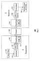
- FIG. 1 shows a multi-antenna system 100 that uses the antenna selection method according to the invention.
- L t data streams 101 are generated. These streams can be either different signals obtained through a space-time coder, i.e., in multiplexing transmission, or the same signal encoded with different weights, i.e., in diversity transmission.
- the streams are modulated 110 to passband RF signals.
- a selection switch 120 links these signals to L t of the t branches 121 associated with the t transmit antennas ( t ⁇ L t ).
- the t passband branches 121 are transformed 130 by a t x t matrix operation ⁇ 1 before they are applied to the t transmit antennas, and passed through the channel 140.
- the signals are received via the channel 140 by r antennas.
- the received signals are transformed 150 by an r x r matrix operation ⁇ 2 , and L r of the transformed signals are selected 160, where L r ⁇ r .
- the selected signals 161 are demodulated 170 and further processed 180 in baseband for detection of the data streams 101.
- the concatenation of the L t out of t switch and the t x t matrix operation ⁇ 1 can be viewed, and implemented, as a t x L t matrix operation in both the transmitter and the receiver.
- the entries of the matrix operations usually are constrained to be pure phase shifters without power amplifiers. They can also be done just in the transmitter, or just in the receiver, e.g., by making the corresponding matrix at the other link end, ⁇ 2 or ⁇ 1 , identity matrices.
- H R 1 / 2 ⁇ WT 1 / 2 , where W is a Rayleigh fading matrix with i.i.d. complex Gaussian enties ⁇ N C (0,1).
- the correlation matrices R and T denote receive and transmit correlations, respectively.
- the sizes of R and T are r ⁇ r and t ⁇ t , respectively. This model is usually valid when assuming independent transmit and receive correlations.
- H U ⁇ V*, where U and V are unitary matrices representing the left and right singular vector spaces of H, respectively; and ⁇ is the diagonal matrix consisting of all the singular values of H.
- ⁇ i ( H ) the i -th largest singular value of matrix H
- u i ( H ) the left and right singular vectors of H with respect to ⁇ i ( H ).
- '*' to denote the conjugate transpose of a vector or matrix (It reduces to the complex conjugate for a scalar).
- the system 100 with diversity transmission can be expressed by a linear equation 1.
- x ⁇ k H ⁇ ⁇ ⁇ ⁇ s k + n ⁇ k , where s ( k ) ⁇ C is the transmitting stream, x ( k ) ⁇ C r is the set of sample stacks of the complex-valued receiver data sequence. The total transmission power is constrained to P .
- the received signals x are weighted with complex weights u * and added, to give a soft estimate of the transmitted symbol stream.
- the estimate SNR after combining is
- each selection option corresponds to a L r ⁇ r selection matrix on the transfer function, which extracts L r out of the r rows of the matrix H that are associated with the selected antennas.
- S r the set of all such selection matrices.
- an L t out of t selection in the transmit end can be represented by a t ⁇ L t matrix, and the set of the transmit selection matrices are denoted by S t .
- the HS-MRC scheme selects the optimal antenna subset selection matrices (S 1 ,S 2 ) among all the elements in S t and S r that maximize the estimate SNR above:
- SNR HS max S 2 ⁇ S r max S 1 ⁇ S t ⁇ ⁇ ⁇ ⁇ 1 2 S 2 ⁇ H ⁇ S 1 .
- the operation ( ⁇ 1 or ⁇ 2 ) 150 can be a fast Fourier transform matrix of the form:
- a more general design in our invention is to allow phase-shift-only entries in the transform ⁇ 1 130 (and/or ⁇ 2 150).
- the transform matrix 130 (150) and the selection 120 (160) can be integrated into one t ⁇ L t (or L r ⁇ r ) matrix with phase-shift-only entries.
- the set of all such transmit (or receive) matrices is denoted by F t (or F r ).
- the linear combining is performed on the virtual channel F 2 HF 1 .
- the optimal solution for equation (8) can be derived in a closed form.
- s ( k ) ⁇ C t is now a t -dimensional vector denoting the different transmitting sequences.
- the assumptions on the channel and noise are the same as the diversity transmission case.
- capacity is an important measure for the capacity of the system.
- the FFT matrix is inserted in the RF chains together with the selection switch.
- the invention provides an alternative method.
- there is no knowledge about the instantaneous channel state but rather only about the state of the channel averaged over a time interval, e.g., typically, but not restricted to, several milliseconds to several hundreds of milliseconds. This case typically occurs for the transmitter in a frequency-division duplexing system.
- the goal of the transformation is to transform the transmit signal in such a way that on average the signals after the selection process has good properties, e.g., high capacity.
- the expected value of the capacity is only one possible criterion. Other criteria result in different values for the capacity matrix.
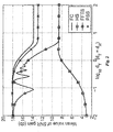
- Figure 2 compares the SNR gain of the four methods described above as a function of antenna spacing with diversity transmission.
- the FFTS method in the invention has a considerably larger SNR gain over the traditional HS-MRT/MRC method.
- the PPS method in the invention can outperform both prior art selection methods.
- the PSS method can achieve the SNR gain of a full-complexity method.
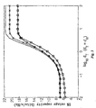
- Figure 3 displays the 5% outage capacity of the four methods for multiplexing transmission.
- the FFTS shows a performance improvement for strongly correlated channels while the PPS works well for both strong and weak correlations.
Landscapes
- Engineering & Computer Science (AREA)
- Computer Networks & Wireless Communication (AREA)
- Signal Processing (AREA)
- Radio Transmission System (AREA)
- Mobile Radio Communication Systems (AREA)
Claims (8)
- Verfahren zum Verarbeiten von RF-Signalen in einem Mehrantennensystem (100), welches aufweist:Erzeugen von
 Gewichten jedes der Lt-Eingangsdatenströme;Modulieren der Lt-Eingangsdatenströme in RF-Signale;Schalten der RF-Signale zu Lt der t Zweige, die mit t Sendeantennen assoziiert sind (t ≥ Lt), mittels einer Sendeauswahlmatrix S1;Anwenden einer Phasenschiebetransformation bei den RF-Signalen mittels einer Sendephasenschiebematrix Φ1 der Dimension t x t, deren Ausgangssignale t RF-Signale sind;Übertragen der t RF-Signale über einen Kanal durch die t Sendeantennen;Empfangen der übertragenen Signale durch
 Anwenden einer Phasenschiebetransformation bei den r RF-Signalen mittels einer Empfangsphasenschiebematrix Φ2 der Dimension r x r;Auswählen von
 Summieren der Lt gewichteten Datenströme;Demodulieren der Lr Signalströme; undVerarbeiten im Basisband, um Ausgangsdatenströme entsprechend den Eingangsdatenströmen wiederzugewinnen,dadurch gekennzeichnet, dass die Phasenschiebeoperatoren Φ1 und Φ2 sowie die Auswahlmatrizen S1 und S2 in einer solchen Weise gesetzt sind, dass der SNR (Störabstand) der empfangenen Signale gemäß einer der folgenden Formeln erhöht wird:
worin
λ1 der größte singuläre Wert von H ist,
H die Kanalübertragungsfunktion ist,
S1∈St ist, S2∈Sr ist (St und Sr sind der Satz von Auswahlmatrizen zum Senden bzw. Empfangen),
ωr 2π/r ist, oder
worin
v ein t-dimensionaler Sendergewichtungsvektor ist, der ∥v ∥= 1 genügt,
u * ein komplexer Empfängergewichtungsvektor entsprechend dem größten singulären Wert λ1 (H) ist,
F1∈Ft, F2∈Fr (Ft und Fr sind alle Sende- bzw. Empfangsmatrizen enthaltend das Produkt aus den Auswahlmatrizen und den Phasenschiebematrizen des Senders bzw. Empfängers. - Verfahren nach Anspruch 1, bei dem die Lt Eingangsdatenströme durch einen Raum-Zeit-Blockcodierer erzeugt werden.
- Verfahren nach Anspruch 1, bei dem die Lt Eingangsdatenströme durch einen Raum-Zeit-Trellis-Codierer erzeugt werden.
- Verfahren nach Anspruch 1, bei dem die Eingangsdatenströme geschichtete Raum-Zeit-Strukturen sind.
- Verfahren nach Anspruch 1, bei dem t = Lt ist und die Matrix Φ1 eine Identitätsmatrix ist.
- Verfahren nach Anspruch 1, bei dem r = Lr ist und die Matrix Φ2 eine Identitätsmatrix ist.
- Verfahren nach Anspruch 1, bei dem die Positionen der Phasenschiebematrizen einer Schätzung eines augenblicklichen Kanalzustandes angepasst sind.
- Verfahren nach Anspruch 2, bei dem die Positionen der Phasenschiebematrizen einer Schätzung eines durchschnittlichen Kanalzustandes angepasst sind.
Applications Claiming Priority (3)
| Application Number | Priority Date | Filing Date | Title |
|---|---|---|---|
| US10/629,240 US7382840B2 (en) | 2003-07-29 | 2003-07-29 | RF signal processing in multi-antenna systems |
| US629240 | 2003-07-29 | ||
| PCT/JP2004/010423 WO2005011186A1 (en) | 2003-07-29 | 2004-07-15 | Method for processing rf signals in multi-antenna systems |
Publications (2)
| Publication Number | Publication Date |
|---|---|
| EP1527544A1 EP1527544A1 (de) | 2005-05-04 |
| EP1527544B1 true EP1527544B1 (de) | 2009-04-01 |
Family
ID=34103572
Family Applications (1)
| Application Number | Title | Priority Date | Filing Date |
|---|---|---|---|
| EP04747812A Expired - Lifetime EP1527544B1 (de) | 2003-07-29 | 2004-07-15 | Verfahren zur verarbeitung eines rf-signals in mehrantennensystemen |
Country Status (6)
| Country | Link |
|---|---|
| US (1) | US7382840B2 (de) |
| EP (1) | EP1527544B1 (de) |
| JP (1) | JP4481306B2 (de) |
| CN (1) | CN100407613C (de) |
| DE (1) | DE602004020304D1 (de) |
| WO (1) | WO2005011186A1 (de) |
Families Citing this family (21)
| Publication number | Priority date | Publication date | Assignee | Title |
|---|---|---|---|---|
| US7952511B1 (en) | 1999-04-07 | 2011-05-31 | Geer James L | Method and apparatus for the detection of objects using electromagnetic wave attenuation patterns |
| US7296045B2 (en) * | 2004-06-10 | 2007-11-13 | Hasan Sehitoglu | Matrix-valued methods and apparatus for signal processing |
| EP1691448A1 (de) * | 2005-02-09 | 2006-08-16 | Research In Motion Limited | Mobiles drahtloses Kommunikationsgerät mit Strahlungsdiagramm-/Frequenzsteuerungsmerkmalen und zugehöriges Verfahren |
| US7890133B2 (en) * | 2005-02-09 | 2011-02-15 | Research In Motion Limited | Mobile wireless communications device providing pattern/frequency control features and related methods |
| WO2007048427A1 (en) * | 2005-10-27 | 2007-05-03 | Telecom Italia S.P.A. | Method and system for multiple antenna communications using multiple transmission modes, related apparatus and computer program product |
| US7657244B2 (en) * | 2005-10-27 | 2010-02-02 | Samsung Electronics Co., Ltd. | Methods of antenna selection for downlink MIMO-OFDM transmission over spatial correlated channels |
| US7558330B2 (en) * | 2005-12-07 | 2009-07-07 | Telefonaktiebolaget L M Ericsson (Publ) | Multiple stream co-phasing for multiple-input-multiple-output (MIMO) systems |
| WO2007108885A2 (en) | 2006-02-28 | 2007-09-27 | Rotani, Inc. | Methods and apparatus for overlapping mimo antenna physical sectors |
| US7974360B2 (en) * | 2006-05-24 | 2011-07-05 | Qualcomm Incorporated | Multi input multi output (MIMO) orthogonal frequency division multiple access (OFDMA) communication system |
| EP2113145B1 (de) * | 2006-11-29 | 2011-01-19 | Telecom Italia S.p.A. | Schaltstrahlantennensystem und verfahren mit digital gesteuerter gewichteter hochfrequenz-kombinierung |
| WO2009080058A1 (en) * | 2007-12-19 | 2009-07-02 | Telecom Italia S.P.A. | Method and systems for receiving plural informations flows in a mimo system |
| WO2009080057A1 (en) * | 2007-12-19 | 2009-07-02 | Telecom Italia S.P.A. | Method and system for switched beam antenna communications |
| US8340197B2 (en) * | 2008-02-28 | 2012-12-25 | Invertix Corporation | System and method for modulating a signal at an antenna |
| US8411794B2 (en) | 2008-11-25 | 2013-04-02 | Invertix Corporation | System and method for arbitrary phase and amplitude modulation in an antenna |
| US8391376B2 (en) * | 2008-11-25 | 2013-03-05 | Invertix Corporation | System and method for electronically steering an antenna |
| US8457251B2 (en) * | 2008-11-25 | 2013-06-04 | Invertix Corporation | System and method for spreading and de-spreading a signal at an antenna |
| IL214213A0 (en) * | 2010-07-20 | 2011-08-31 | Coppergate Comm Ltd | Transmission scheme for multiple-input communication |
| US9407337B2 (en) * | 2013-04-15 | 2016-08-02 | Broadcom Corporation | Antenna systems and methods for massive MIMO communication |
| WO2015054838A1 (en) * | 2013-10-16 | 2015-04-23 | Empire Technology Development Llc | Spatial modulation multiple-input-multiple-output (sm-mimo) system |
| US9705579B2 (en) | 2014-06-06 | 2017-07-11 | Ntt Docomo, Inc. | Transceivers and methods for use in transmitting information in a massive MIMO system |
| US12596019B1 (en) * | 2023-03-15 | 2026-04-07 | The Government Of The United States Of America, As Represented By The Secretary Of The Navy | RF spectrum analyzer using Rayleigh backscattering |
Family Cites Families (16)
| Publication number | Priority date | Publication date | Assignee | Title |
|---|---|---|---|---|
| GB2267783B (en) * | 1992-06-09 | 1996-08-28 | British Aerospace | Beam forming |
| US6243565B1 (en) * | 1996-06-18 | 2001-06-05 | Telefonaktiebolaget Lm Ericsson (Publ) | Method and apparatus for transmitting communication signals using frequency and polarization diversity |
| CA2302289C (en) * | 1996-08-29 | 2005-11-08 | Gregory G. Raleigh | Spatio-temporal processing for communication |
| FI104133B (fi) * | 1997-11-28 | 1999-11-15 | Nokia Mobile Phones Ltd | Koodaus- ja modulointimenetelmä ja laite sen soveltamiseksi |
| AU6257399A (en) * | 1998-09-18 | 2000-04-10 | Hesham El Gamal | Method and constructions for space-time codes for psk constellations for spatialdiversity in multiple-element antenna systems |
| US6678512B1 (en) * | 2000-04-14 | 2004-01-13 | Lucent Technologies Inc. | Receiver system using analog to digital conversion at radio frequency and method |
| KR100493152B1 (ko) * | 2000-07-21 | 2005-06-02 | 삼성전자주식회사 | 이동 통신 시스템에서의 전송 안테나 다이버시티 방법 및이를 위한 기지국 장치 및 이동국 장치 |
| US6937592B1 (en) * | 2000-09-01 | 2005-08-30 | Intel Corporation | Wireless communications system that supports multiple modes of operation |
| AU2001223628A1 (en) | 2000-12-06 | 2002-06-18 | Nokia Corporation | Method for controlling the weighting of a data signal in the at least two antenna elements of a radio connection unit, module and communications system |
| US6870515B2 (en) * | 2000-12-28 | 2005-03-22 | Nortel Networks Limited | MIMO wireless communication system |
| US7050510B2 (en) * | 2000-12-29 | 2006-05-23 | Lucent Technologies Inc. | Open-loop diversity technique for systems employing four transmitter antennas |
| US6917820B2 (en) * | 2001-01-26 | 2005-07-12 | Stanford University | Method and apparatus for selection and use of optimal antennas in wireless systems |
| WO2002089252A1 (en) * | 2001-04-26 | 2002-11-07 | Koninklijke Philips Electronics N.V. | A method and system for forming an antenna pattern |
| GB0125178D0 (en) * | 2001-10-19 | 2001-12-12 | Koninkl Philips Electronics Nv | Method of operating a wireless communication system |
| US7020215B2 (en) * | 2002-03-19 | 2006-03-28 | Motorola, Inc. | Method and apparatus for reducing transmitter peak power requirements using dual matrices |
| FI20020880A0 (fi) * | 2002-05-08 | 2002-05-08 | Nokia Corp | Tiedonsiirtomenetelmä - ja järjestelmä |
-
2003
- 2003-07-29 US US10/629,240 patent/US7382840B2/en not_active Expired - Lifetime
-
2004
- 2004-07-15 JP JP2006519230A patent/JP4481306B2/ja not_active Expired - Lifetime
- 2004-07-15 DE DE602004020304T patent/DE602004020304D1/de not_active Expired - Lifetime
- 2004-07-15 EP EP04747812A patent/EP1527544B1/de not_active Expired - Lifetime
- 2004-07-15 CN CN200480000885XA patent/CN100407613C/zh not_active Expired - Lifetime
- 2004-07-15 WO PCT/JP2004/010423 patent/WO2005011186A1/en not_active Ceased
Also Published As
| Publication number | Publication date |
|---|---|
| CN1701555A (zh) | 2005-11-23 |
| JP2007536765A (ja) | 2007-12-13 |
| US7382840B2 (en) | 2008-06-03 |
| CN100407613C (zh) | 2008-07-30 |
| JP4481306B2 (ja) | 2010-06-16 |
| US20050025271A1 (en) | 2005-02-03 |
| WO2005011186A1 (en) | 2005-02-03 |
| DE602004020304D1 (de) | 2009-05-14 |
| EP1527544A1 (de) | 2005-05-04 |
Similar Documents
| Publication | Publication Date | Title |
|---|---|---|
| US7382840B2 (en) | RF signal processing in multi-antenna systems | |
| EP1671432B1 (de) | System und verfahren zur antennenauswahl | |
| EP1654891B1 (de) | Gewichtserzeugungsverfahren für mehrantennen-kommunikationssysteme unter verwendung einer hf-gestützten und basisband-signalgewichtung und kombinierung | |
| US6987819B2 (en) | Method and device for multiple input/multiple output transmit and receive weights for equal-rate data streams | |
| EP1606916B1 (de) | Mehrantennenkommunikationssystememit signalgewichtung und kombinierung auf hf- und basisbandbasis | |
| Chen et al. | Performance analysis of maximum ratio transmission with imperfect channel estimation | |
| Khalighi et al. | Water filling capacity of Rayleigh MIMO channels | |
| EP1843485B1 (de) | MIMO Raummultiplexsystem mit einer dynamischen Fähigkeit zum selektieren einer Antennenstrahlkombination. | |
| EP1284545B1 (de) | Drahtlose Kommunikation mit Sendediversität | |
| CN1813375B (zh) | 多天线传输方法和装置 | |
| EP1858176A2 (de) | Drahtloses MIMO-Datenkommunikationssystem, drahtloses MIMO-Datenkommunikationsverfahren und drahtlose MIMO-Datenkommunikationsvorrichtung | |
| JP2008503903A (ja) | 無線チャネルにより接続された複数の送信アンテナ及び複数の受信アンテナを含む多入力多出力通信システムにおけるrf信号の処理方法 | |
| CN105071847A (zh) | 传输设备、方法以及接收设备 | |
| EP1880486B1 (de) | Verfahren zum übertragen von trainings-frames in einem mimo-system sowie mimo-system | |
| EP1830487B1 (de) | Multi-Input-/Multi-Output(MIMO)-Kommunikationsvorrichtung | |
| Loyka et al. | On the use of Jensen's inequality for MIMO channel capacity estimation | |
| CN101350648A (zh) | 一种实现发射的方法、系统及发射机 | |
| Shrivastava et al. | Combined beamforming with space-time-frequency coding for MIMO–OFDM systems | |
| Mitsui et al. | Indoor MIMO channel measurements for evaluation of effectiveness of array antenna configurations | |
| Badran | DWT-based joint antenna selection for correlated MIMO channels | |
| Abouda et al. | Effect of mutual coupling on BER performance of Alamouti scheme | |
| US11115085B1 (en) | MIMO-OFDM system for increasing reliability | |
| Molisch | MIMO systems with full and reduced hardware complexity | |
| de Lamare et al. | Blind adaptive space-time block-coded receivers for DS-CDMA systems in multipath channels based on the constant modulus criterion | |
| Mishra | Capacity Analysis of a MIMO-OFDM System Using Spatial Multiplexing with Beamforming in Multiuser Environment |
Legal Events
| Date | Code | Title | Description |
|---|---|---|---|
| PUAI | Public reference made under article 153(3) epc to a published international application that has entered the european phase |
Free format text: ORIGINAL CODE: 0009012 |
|
| 17P | Request for examination filed |
Effective date: 20050308 |
|
| AK | Designated contracting states |
Kind code of ref document: A1 Designated state(s): AT BE BG CH CY CZ DE DK EE ES FI FR GB GR HU IE IT LI LU MC NL PL PT RO SE SI SK TR |
|
| AX | Request for extension of the european patent |
Extension state: AL HR LT LV MK |
|
| 17Q | First examination report despatched |
Effective date: 20050518 |
|
| RAP1 | Party data changed (applicant data changed or rights of an application transferred) |
Owner name: MITSUBISHI DENKI KABUSHIKI KAISHA Owner name: KUNG, SUN YUAN |
|
| DAX | Request for extension of the european patent (deleted) | ||
| RBV | Designated contracting states (corrected) |
Designated state(s): DE FR GB |
|
| GRAP | Despatch of communication of intention to grant a patent |
Free format text: ORIGINAL CODE: EPIDOSNIGR1 |
|
| GRAS | Grant fee paid |
Free format text: ORIGINAL CODE: EPIDOSNIGR3 |
|
| GRAA | (expected) grant |
Free format text: ORIGINAL CODE: 0009210 |
|
| AK | Designated contracting states |
Kind code of ref document: B1 Designated state(s): DE FR GB |
|
| REG | Reference to a national code |
Ref country code: GB Ref legal event code: FG4D |
|
| REF | Corresponds to: |
Ref document number: 602004020304 Country of ref document: DE Date of ref document: 20090514 Kind code of ref document: P |
|
| PLBE | No opposition filed within time limit |
Free format text: ORIGINAL CODE: 0009261 |
|
| STAA | Information on the status of an ep patent application or granted ep patent |
Free format text: STATUS: NO OPPOSITION FILED WITHIN TIME LIMIT |
|
| 26N | No opposition filed |
Effective date: 20100105 |
|
| REG | Reference to a national code |
Ref country code: FR Ref legal event code: PLFP Year of fee payment: 13 |
|
| REG | Reference to a national code |
Ref country code: FR Ref legal event code: PLFP Year of fee payment: 14 |
|
| REG | Reference to a national code |
Ref country code: FR Ref legal event code: PLFP Year of fee payment: 15 |
|
| PGFP | Annual fee paid to national office [announced via postgrant information from national office to epo] |
Ref country code: FR Payment date: 20230608 Year of fee payment: 20 |
|
| PGFP | Annual fee paid to national office [announced via postgrant information from national office to epo] |
Ref country code: GB Payment date: 20230601 Year of fee payment: 20 |
|
| PGFP | Annual fee paid to national office [announced via postgrant information from national office to epo] |
Ref country code: DE Payment date: 20230531 Year of fee payment: 20 |
|
| REG | Reference to a national code |
Ref country code: GB Ref legal event code: PE20 Expiry date: 20240714 |
|
| PG25 | Lapsed in a contracting state [announced via postgrant information from national office to epo] |
Ref country code: GB Free format text: LAPSE BECAUSE OF EXPIRATION OF PROTECTION Effective date: 20240714 |
|
| PG25 | Lapsed in a contracting state [announced via postgrant information from national office to epo] |
Ref country code: GB Free format text: LAPSE BECAUSE OF EXPIRATION OF PROTECTION Effective date: 20240714 |