EP1526724A2 - Multimedia display device - Google Patents
Multimedia display device Download PDFInfo
- Publication number
- EP1526724A2 EP1526724A2 EP04256492A EP04256492A EP1526724A2 EP 1526724 A2 EP1526724 A2 EP 1526724A2 EP 04256492 A EP04256492 A EP 04256492A EP 04256492 A EP04256492 A EP 04256492A EP 1526724 A2 EP1526724 A2 EP 1526724A2
- Authority
- EP
- European Patent Office
- Prior art keywords
- docking station
- image projection
- projection device
- projector
- display device
- Prior art date
- Legal status (The legal status is an assumption and is not a legal conclusion. Google has not performed a legal analysis and makes no representation as to the accuracy of the status listed.)
- Withdrawn
Links
- 238000003032 molecular docking Methods 0.000 claims abstract description 116
- 238000000034 method Methods 0.000 claims description 18
- 230000008878 coupling Effects 0.000 claims description 9
- 238000010168 coupling process Methods 0.000 claims description 9
- 238000005859 coupling reaction Methods 0.000 claims description 9
- 230000006870 function Effects 0.000 description 8
- 230000000007 visual effect Effects 0.000 description 3
- 230000006835 compression Effects 0.000 description 2
- 238000007906 compression Methods 0.000 description 2
- 238000001816 cooling Methods 0.000 description 2
- 239000000835 fiber Substances 0.000 description 2
- 239000004973 liquid crystal related substance Substances 0.000 description 2
- 230000002093 peripheral effect Effects 0.000 description 2
- 230000005236 sound signal Effects 0.000 description 2
- XUIMIQQOPSSXEZ-UHFFFAOYSA-N Silicon Chemical compound [Si] XUIMIQQOPSSXEZ-UHFFFAOYSA-N 0.000 description 1
- 238000005452 bending Methods 0.000 description 1
- 230000005540 biological transmission Effects 0.000 description 1
- 238000000071 blow moulding Methods 0.000 description 1
- 238000005266 casting Methods 0.000 description 1
- 238000006243 chemical reaction Methods 0.000 description 1
- 239000002131 composite material Substances 0.000 description 1
- 230000001143 conditioned effect Effects 0.000 description 1
- 230000003750 conditioning effect Effects 0.000 description 1
- 238000005034 decoration Methods 0.000 description 1
- 238000013461 design Methods 0.000 description 1
- 238000005242 forging Methods 0.000 description 1
- 230000017525 heat dissipation Effects 0.000 description 1
- 238000010348 incorporation Methods 0.000 description 1
- 238000001746 injection moulding Methods 0.000 description 1
- 238000004519 manufacturing process Methods 0.000 description 1
- 239000000463 material Substances 0.000 description 1
- 239000002184 metal Substances 0.000 description 1
- 229910052751 metal Inorganic materials 0.000 description 1
- 150000002739 metals Chemical class 0.000 description 1
- 238000012986 modification Methods 0.000 description 1
- 230000004048 modification Effects 0.000 description 1
- 238000000465 moulding Methods 0.000 description 1
- 230000003287 optical effect Effects 0.000 description 1
- 239000004033 plastic Substances 0.000 description 1
- 229920003023 plastic Polymers 0.000 description 1
- 238000012545 processing Methods 0.000 description 1
- 238000001175 rotational moulding Methods 0.000 description 1
- 229910052710 silicon Inorganic materials 0.000 description 1
- 239000010703 silicon Substances 0.000 description 1
- 230000001360 synchronised effect Effects 0.000 description 1
- 238000009423 ventilation Methods 0.000 description 1
Images


Classifications
-
- H—ELECTRICITY
- H04—ELECTRIC COMMUNICATION TECHNIQUE
- H04N—PICTORIAL COMMUNICATION, e.g. TELEVISION
- H04N9/00—Details of colour television systems
- H04N9/12—Picture reproducers
- H04N9/31—Projection devices for colour picture display, e.g. using electronic spatial light modulators [ESLM]
- H04N9/3141—Constructional details thereof
-
- H—ELECTRICITY
- H04—ELECTRIC COMMUNICATION TECHNIQUE
- H04N—PICTORIAL COMMUNICATION, e.g. TELEVISION
- H04N5/00—Details of television systems
- H04N5/64—Constructional details of receivers, e.g. cabinets or dust covers
- H04N5/642—Disposition of sound reproducers
Definitions
- Portable and stationary audio and visual (A/V) equipment are widely used in business and by consumers. Many users of A/V equipment own multiple devices, each device designed to fill a certain audio and/or video function. For example, in the field of sound, a user may have a portable compact disc (CD) player, a portable motion picture entertainment group compression format number three (MP3) player, a portable AM/FM radio, etc. The same user may also have a stationary CD player, a stationary MP3 player, a stationary AM/FM radio, etc. located at their home. A similar situation exists for video equipment. A user may have a portable video projector, digital versatile/video disc (DVD) player, television (TV), etc. as well as a stationary video projector, DVD player, TV, etc.
- DVD digital versatile/video disc
- portable video projectors are commonly used in business meetings or conferences to project slide presentations or other images onto a screen to aid in the presentation.
- the projector is typically connected to a notebook computer or another portable computing system such as a personal digital assistant (PDA).
- PDA personal digital assistant
- the notebook computer outputs a display and/or audio signal, which is then connected to the projector via a number of cables.
- the video signal may be transmitted in one of a variety of manners which include S-Video, component video, digital visual interface (DVI), red green blue horizontal sync vertical sync (RGBHV), video graphics array (VGA), super video graphics array (SVGA), etc. Each method of transmission utilizes a specialized cable.
- a multimedia display device includes a docking station having speakers and a media drive, wherein the docking station is configured to structurally and communicatively couple an image projection device to the docking station.
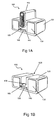
- Fig. 1A is a perspective view of an image projection device vertically docked in a docking station according to one exemplary embodiment.
- Fig. 1B is a perspective view of an empty docking station according to one exemplary embodiment.
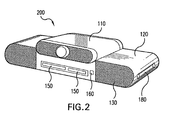
- Fig. 2 is a perspective view showing an image projection device horizontally docked in a docking station according to one exemplary embodiment.
- Fig. 3 is a perspective view of an image projection device docked in a docking station according to one exemplary embodiment.
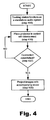
- Fig. 4 is a flow chart describing a method of operating the present system according to one exemplary embodiment.
- Fig. 5 is a perspective view of an empty docking station including an automatic docking bay according to one exemplary embodiment.
- the present specification describes a method and a system for docking an image projection device in a docking station while electronically coupling the image projection device to the docking station.
- the image projection device has increased utility.
- the docking station may resemble a conventional boom box or shelf stereo system both aesthetically and functionally.
- a docking station is meant to be understood broadly as any hardware frame and set of electrical connection interfaces that enable an image projection device to be coupled to and communicate with any number of peripheral components.
- a docking station can also include a network interface card (NIC) that attaches the image projection device to a local area network (LAN).
- NIC network interface card
- a docking station may include buttons and/or a remote control for controlling the docking station functions, an infrared (IR) sensor, audio and video outputs, attached or detachable speakers, an interconnect for connecting a projector to the docking station, etc.
- peripheral component is meant to be understood as any number of media accessing components including, but in no way limited to, one or more of the following: a CD player, a DVD player, a CD/DVD combination drive capable of playing any variation of writable and rewritable discs, a cassette player, a hard disk device (HDD), or an MP3 player.
- Figure 1A illustrates an exemplary embodiment of a media system (100) configured to couple a docking station to a vertically mounting image projection device.
- the media system (100) includes a docking station (120) coupled to a vertically mounting image projection device (110).
- the image projection device or "projector” (110) illustrated in Figure 1A is docked in a cavity (125; Fig. 1B), formed in the body of the docking station (120), configured to vertically receive and hold a projector.
- Figure 1A also illustrates that the docking station (120) may include a number of speakers (130), control buttons (140), media drives (150), and an infrared (I/R) sensor (160).
- the media system (100) illustrated in Figure 1A may be designed to hold the projector (110) horizontally as shown in Figure 2, vertically as shown in Figure 1A, or in any other desirable orientation.
- the image projection device or projector (110) may be any type of image projection device including, but in no way limited to, a liquid crystal display (LCD) projector, a digital light processing (DLP) projector, a liquid crystal on silicon (LCOS) projector, a slide projector, a film projector, etc.
- the image projection device (110) illustrated in Figure 1A may include both video and audio inputs, as will be familiar to one skilled in the art.
- the docking station (120) illustrated in Figure 1A is configured to receive and be communicatively coupled to an image projection device (110).
- the docking station (120) may be composed of any material capable of providing structural support to the docking station's internal components as well as a coupled image projection device (110) including, but in no way limited to, plastics, metals, or composite materials.
- the docking station may be fabricated using any number of fabrication techniques including, but in no way limited to, roto molding, blow molding, deep draw molding, injection molding, casting, forging, or stamping.
- the components that may be housed in the present docking station (120) may include speakers (130), control buttons (140), media drives (150), and an I/R sensor. The above-mentioned components will now be described in further detail below.
- a number of speakers (130) may be disposed in the docking station (120) according to one exemplary embodiment. While Figure 1A illustrates a docking station (120) housing two speakers (130), the docking station may be electronically coupled to any number of speakers. According to the embodiment illustrated in Figure 1A, two speakers (130) may be disposed in the docking station (120) to provide a user the possibility of stereo sound. Similarly, five or more speakers (130) may be disposed in and electronically coupled to the docking station (120). Five or more speakers disposed in the docking station provide the user with the ability to produce surround sound according to Dolby Pro Logic® standards. Moreover, the present system and method may also be utilized in connection with a docking station (120) having a single speaker (120) or any number of speakers (120) disposed therein.
- the docking station (120) may house one or more media drives (150) including, but in no way limited to, a compact disc read-only memory (CD-ROM) drive, a recordable CD (CD-R) drive, a rewritable CD (CD-RW) drive, a digital versatile disc read-only memory (DVD-ROM) drive, a recordable DVD (DVD ⁇ R) drive, a rewritable DVD (DVD ⁇ RW) drive, a motion picture entertainment group compression format number three (MP3) drive, a DVD/CD/CDRW/MP3 combination drive, a cassette drive, a memory stick or memory card slot, a hard disk device (HDD), etc.
- CD-ROM compact disc read-only memory
- CD-R recordable CD
- CD-RW rewritable CD
- DVD-ROM digital versatile disc read-only memory
- DVD ⁇ R recordable DVD
- DVD ⁇ RW rewritable DVD
- MP3 motion picture entertainment group compression format number three
- any combination of the above-mentioned media drives (150) may be housed in and electronically coupled to the present docking station (120). Once electronically coupled to the present docking station (120), the coupled media drives (150) may produce any number of audio and/or video signals that may be routed to and processed by the speakers (130) and the projection device (110), respectively, or through external A/V outputs on the docking station (120) (not shown).
- Figure 1A also illustrates a number of control buttons (140) disposed on the docking station (120).
- the control buttons (140) disposed on the docking station may include any number of control buttons that facilitate or enable the use of the docking station, coupled media drives (150), or a coupled image projection device (110).
- the control buttons (140) disposed on one exemplary embodiment of the docking station (120) may include, but are in no way limited to, a play button, a stop button, a fast forward button, a rewind button, a previous/next track button, a record button, a volume button, a function button, a mute button, etc.
- the exemplary media system (100) illustrated in Figure 1A also demonstrates the incorporation of an infrared (I/R) sensor (160) in the docking station (120).
- the docking station (120) may include a coupled I/R sensor (160) which allows the user to remotely select between inputs and control the functions of the docking station (120), coupled media drives (150), and/or a coupled image projection device (110).
- a coupled I/R sensor 160
- the user may select a button on a wireless remote control (not shown) programmed to emit infrared signals at a frequency designated to activate the desired media drive.
- the emitted infrared signals may then be detected by the I/R sensor (160) which then transmits signals that control the desired media drive (150).
- Other means of sending infrared signals to control the docking station (120) and/or the projector (110) through the I/R sensor (160) include, but are in no way limited to, transmitting infrared signals with a personal digital assistant (PDA), a cell phone, a notebook computer, or a digital watch.
- PDA personal digital assistant
- Figure 1B illustrates a media system (100) without an image projection device (110; Fig. 1A) coupled thereto.
- a projector reception cavity (125) and a system coupling connection (170) are visible.
- a user may place an image projection device (110; Fig. 1A) into the projector reception cavity (125) where the projection device is automatically physically and electrically coupled to the docking station (120).
- video or audio signal from the docking station (120) or one of its associated media drives (150) may be projected with the image projection device (110; Fig. 1A) or emitted by the coupled speakers (130).
- the entire media system (100) may function as a single compact media presentation unit.
- the projector reception cavity (125) illustrated in Figure 1B may be any cavity configured to structurally support and hold an image projection device (110; Fig. 1A) while enabling the image projection device to be physically and electronically coupled to the docking station (120). Additionally, the projector reception cavity (125) provides sufficient ventilation for cooling of the image projection device (110; Fig. 1A) during extended periods of image projection. Cooling or heat dissipation away from the image projection device (110; Fig. 1A) may be accomplished by the reception cavity (125) through any number of known methods including, but in no way limited to, natural convection or forced convection. Additionally, the projection reception cavity (125) may provide a power source configured to provide power to the projection device (110; Fig.
- the cavity (125) may be an oval shaped depression formed in the docking station (120) configured to be molded to the shape of an image projection device (110; Fig. 1A).
- the projector reception cavity (125) may be a planar shelf or any other shaped shelf upon which the image projection device (110; Fig. 1A) may rest.
- connection (170) may be disposed in the projector reception cavity (125).
- the connection (170) disposed in the projector reception cavity may be specifically designed to enable the automatic coupling of an image projection device (110; Fig. 1A) to the docking station (120).
- This connection (170) may include but is in no way limited to, a universal serial bus (USB), small computer system interface (SCSI), Bluetooth, IEEE 1394 high speed serial bus, parallel, serial, RCA, coaxial cable, fiber optic, wireless, or other proprietary means of electronic connection.
- a corresponding connection (not shown) may be present on the image projection device (110; Fig. 1A) to further facilitate the coupling of the image projection device to the docking station (120).
- connection on the image projection device (110; Fig. 1A) may include, but is in no way limited to, a universal serial bus (USB), small computer system interface (SCSI), Bluetooth, IEEE 1394 high speed serial bus, parallel, serial, RCA, coaxial cable, fiber optic, wireless, or other proprietary means of electronic connection.
- USB universal serial bus
- SCSI small computer system interface
- Bluetooth IEEE 1394 high speed serial bus
- parallel, serial, RCA coaxial cable
- fiber optic, wireless or other proprietary means of electronic connection.
- Video, audio, data, optical, or any other desired signals from a remote control, power, or other data may be transmitted from the docking station (120) and its associated media drives (150) to the image projection device (110; Fig. 1A) via the interconnect (170).
- the docking station (120) illustrated in Figure 1B may function as a standalone audio system when it is not coupled to an image projection device (110; Fig. 1A).
- the docking station (120) may be portable or stationary and may function on battery power or regular 120-volt power.
- the docking station (120) may play any form of audio stored on any of the above-mentioned media types including, but in no way limited to, CD audio, MP3's, DVD audio, cassette audio, .wav files, midi files, etc.
- the sound produced by the above-mentioned media types may be output through speakers (130) or through audio outputs built in to the docking station (130).
- the audio and/or video signals generated by the present system and method may be amplified or otherwise conditioned using an amplifier, an equalizer, filters of various types, a digital to analog converter (DAC), etc.
- the signal conditioning may be performed either intemally by the docking station (120) or externally with separate devices.
- the audio and/or video signals may be transmitted directly to the image projection device (110; Fig. 1A) digitally without any analog-to-digital or digital-to-analog conversions.
- FIG 2 is an illustration of an alternative embodiment of a projector (110) docked in a docking station (120).
- the system (200) includes an image projection device (110) horizontally disposed in the docking station (120).
- the interconnect (170, Fig. 1b) coupling the image projection device (110) to the docking station (120) may be located on any surface of the image projection device (110) that may come into direct contact with the docking station (120).
- the projector (110) is placed in the specially formed cavity (125; Fig. 1B) configured to hold the projector (110)
- the projector (110) is automatically electronically and physically coupled to the docking station (120).
- the image projection device (110) and the docking station (120) may act as a single unit and may be controlled as a single unit.
- buttons (140, Fig. 1a) may be disposed on the docking station (120) that, when actuated, may control both audio and video functions.
- a single remote control may also be used to control both the projector (110) and the docking station (120) when the two are electronically coupled.
- Figure 2 also illustrates handles (180) disposed on the docking station (120).
- the present system (200) may be easily transported by a user.
- the handles (180) illustrated in Figure 2 are shown as recessed cavities on the side of each speaker (130).
- the handles incorporated by the present system (200) may be of any shape or form including, but in no way limited to, a strap, recessed cavities, or a moveable handle.
- the docking station (120) and/or the image projection device (110) may be designed and built to various heights, widths, depths, etc., with various decorations, button and media drive layouts, etc.
- the docking station (120) may be designed to accommodate various sizes and shapes of image projection devices (110) and may be adjustable so that the same docking station (120) is capable of coupling a variety of different projectors. While the image projection device (110) illustrated in Figure 2 is shown docked in the docking station (120), the image projection device (110) may be separated from the docking station and used as a normal, portable image projection device.
- FIG. 3 illustrates yet another exemplary embodiment of the present system and method in which an alternative design and layout is used (300).
- the docking station (120) resembles a portable stereo system or "boom box.”
- the docking station (120) illustrated in Figure 3 includes two round speakers (130), a button interface (140) for controlling the docking station (120), an IR sensor (160) for receiving a remote control signal, a media drive (150), and handles (180) for transporting the docking station (120).
- the illustrated docking station (120) has a specially formed cavity configured to receive and horizontally couple an image projection device (110).
- the image projection device (110) shown is completely removable and useable independent of the docking station (120). When the image projection device (110) is placed in the cavity designed to receive the image projection device (110), the image projection device (110) is electronically and physically coupled to the docking station (120) and both may be controlled as a single unit.
- Figure 4 illustrates a method of operating the image projection device (110; Fig. 1A) and the docking station (120; Fig. 1A).
- Both the image projection device (110; Fig. 1A) and the docking station (120; Fig. 1A) may be used separately as standalone devices: the docking station may play audio media and the image projection device may project images (step 400).
- the image projection device (110; Fig. 1A) is coupled to the interconnect (step 410)
- the image projection device is automatically electronically and physically coupled to the docking station (120; Fig. 1A).
- the image projection device (110; Fig. 1A) may project images in synch with corresponding audio that is emitted from the speakers (130; Fig.
- an indicator may be employed to inform the user that the image projection device (110; Fig. 1A) was successfully docked and coupled to the docking station (120; Fig. 1A).
- a light such as a light emitting diode (LED) may turn on, flash, or otherwise indicate that the connection was made.
- the docking station (120) has a visual display, words may be displayed indicating that the connection was made. If the connection is established (YES, step 420), video and audio may be received by the system (100; Fig. 1A) and presented together (step 430). If, however, the connection has not been established (NO, step 420), the image projection device (1-10; Fig. 1A) is reseated in the docking station (120; Fig. 1A).
- FIG. 5 illustrates an alternative docking station (500) including a receiving mechanism (510) designed to accept and mechanically translate an image projection device (110; Fig. 1A) into a docked position, similar to the way a video cassette is mechanically translated by a video cassette recorder (VCR).
- the interconnect (170; Fig. 1B) between the image projection device (110; Fig. 1A) and the docking station (510) is coupled to the image projection device (110; Fig. 1A) as it is mechanically translated into place.
- This method would prevent a user from forcefully inserting an image projection device (110; Fig. 1A) into the docking station (510) and possibly breaking or bending a component.
- the mechanically receiving mechanism (510) ensures that the image projection device (110; Fig. 1A) is properly placed so as to be electronically and physically coupled to the docking station (510).
- the present media system in its various embodiments, is capable of combining the functionality of a stereo audio system and an image projection device. More particularly, a projector may be docked in a docking station where the projector is automatically electronically and physically coupled to the docking station. Media signals may then be transmitted from the docking station to the image projection device through the electronic couple. Once coupled, both devices may act as a single unit outputting synchronous sound and video and may be controlled as a single unit. By using such a docking station, a user may add functionality to an image projection device easily and conveniently.
Landscapes
- Engineering & Computer Science (AREA)
- Multimedia (AREA)
- Signal Processing (AREA)
- Projection Apparatus (AREA)
- Transforming Electric Information Into Light Information (AREA)
Abstract
A multimedia display device includes a docking station (100) having speakers (130) and a media drive (150), wherein the docking station (100) is configured to structurally and communicatively couple an image projection device (110) to the docking station (100).
Description
- Portable and stationary audio and visual (A/V) equipment are widely used in business and by consumers. Many users of A/V equipment own multiple devices, each device designed to fill a certain audio and/or video function. For example, in the field of sound, a user may have a portable compact disc (CD) player, a portable motion picture entertainment group compression format number three (MP3) player, a portable AM/FM radio, etc. The same user may also have a stationary CD player, a stationary MP3 player, a stationary AM/FM radio, etc. located at their home. A similar situation exists for video equipment. A user may have a portable video projector, digital versatile/video disc (DVD) player, television (TV), etc. as well as a stationary video projector, DVD player, TV, etc.
- Additionally, portable video projectors are commonly used in business meetings or conferences to project slide presentations or other images onto a screen to aid in the presentation. The projector is typically connected to a notebook computer or another portable computing system such as a personal digital assistant (PDA). The notebook computer outputs a display and/or audio signal, which is then connected to the projector via a number of cables. The video signal may be transmitted in one of a variety of manners which include S-Video, component video, digital visual interface (DVI), red green blue horizontal sync vertical sync (RGBHV), video graphics array (VGA), super video graphics array (SVGA), etc. Each method of transmission utilizes a specialized cable. Once the notebook computer is connected to the projector, images and/or motion picture may be projected onto a display surface, generally a wall or a screen.
- Often, business people are issued or personally own portable video projectors to use in such meetings and conferences. Many times, these projectors are limited in their use due to the impracticality of connecting and configuring the projector for home or other personal use. Consumers may also have video projectors, which are limited in their use to one room due to the fact that the projector is fastened or permanently mounted to a wall or a ceiling.
- A multimedia display device includes a docking station having speakers and a media drive, wherein the docking station is configured to structurally and communicatively couple an image projection device to the docking station.
- The accompanying drawings illustrate various embodiments of the present method and system and are a part of the specification. The illustrated embodiments are merely examples of the present method and system and do not limit the scope of the present disclosure.
- Fig. 1A is a perspective view of an image projection device vertically docked in a docking station according to one exemplary embodiment.
- Fig. 1B is a perspective view of an empty docking station according to one exemplary embodiment.
- Fig. 2 is a perspective view showing an image projection device horizontally docked in a docking station according to one exemplary embodiment.
- Fig. 3 is a perspective view of an image projection device docked in a docking station according to one exemplary embodiment.
- Fig. 4 is a flow chart describing a method of operating the present system according to one exemplary embodiment.
- Fig. 5 is a perspective view of an empty docking station including an automatic docking bay according to one exemplary embodiment.
- Throughout the drawings, identical reference numbers designate similar, but not necessarily identical, elements.
- The present specification describes a method and a system for docking an image projection device in a docking station while electronically coupling the image projection device to the docking station. By automatically coupling the image projection device to the docking station, the image projection device has increased utility. In some exemplary embodiments, the docking station may resemble a conventional boom box or shelf stereo system both aesthetically and functionally.
- As used in the present specification and in the appended claims, the term "docking station" is meant to be understood broadly as any hardware frame and set of electrical connection interfaces that enable an image projection device to be coupled to and communicate with any number of peripheral components. A docking station can also include a network interface card (NIC) that attaches the image projection device to a local area network (LAN). A docking station may include buttons and/or a remote control for controlling the docking station functions, an infrared (IR) sensor, audio and video outputs, attached or detachable speakers, an interconnect for connecting a projector to the docking station, etc. Similarly, the term "peripheral" component is meant to be understood as any number of media accessing components including, but in no way limited to, one or more of the following: a CD player, a DVD player, a CD/DVD combination drive capable of playing any variation of writable and rewritable discs, a cassette player, a hard disk device (HDD), or an MP3 player.
- In the following description, for purposes of explanation, numerous specific details are set forth in order to provide a thorough understanding of the present system and method for docking an image projection device. It will be apparent, however, to one skilled in the art that the present method may be practiced without these specific details. Reference in the specification to "one embodiment" or "an embodiment" means that a particular feature, structure, or characteristic described in connection with the embodiment is included in at least one embodiment. The appearance of the phrase "in one embodiment" in various places in the specification are not necessarily all referring to the same embodiment.
- Figure 1A illustrates an exemplary embodiment of a media system (100) configured to couple a docking station to a vertically mounting image projection device. As shown in Figure 1A, the media system (100) includes a docking station (120) coupled to a vertically mounting image projection device (110). The image projection device or "projector" (110) illustrated in Figure 1A is docked in a cavity (125; Fig. 1B), formed in the body of the docking station (120), configured to vertically receive and hold a projector. Figure 1A also illustrates that the docking station (120) may include a number of speakers (130), control buttons (140), media drives (150), and an infrared (I/R) sensor (160).
- The media system (100) illustrated in Figure 1A may be designed to hold the projector (110) horizontally as shown in Figure 2, vertically as shown in Figure 1A, or in any other desirable orientation. The image projection device or projector (110) may be any type of image projection device including, but in no way limited to, a liquid crystal display (LCD) projector, a digital light processing (DLP) projector, a liquid crystal on silicon (LCOS) projector, a slide projector, a film projector, etc. Moreover, the image projection device (110) illustrated in Figure 1A may include both video and audio inputs, as will be familiar to one skilled in the art.
- The docking station (120) illustrated in Figure 1A is configured to receive and be communicatively coupled to an image projection device (110). The docking station (120) may be composed of any material capable of providing structural support to the docking station's internal components as well as a coupled image projection device (110) including, but in no way limited to, plastics, metals, or composite materials. Similarly, the docking station may be fabricated using any number of fabrication techniques including, but in no way limited to, roto molding, blow molding, deep draw molding, injection molding, casting, forging, or stamping. The components that may be housed in the present docking station (120) may include speakers (130), control buttons (140), media drives (150), and an I/R sensor. The above-mentioned components will now be described in further detail below.
- As shown in Figure 1A, a number of speakers (130) may be disposed in the docking station (120) according to one exemplary embodiment. While Figure 1A illustrates a docking station (120) housing two speakers (130), the docking station may be electronically coupled to any number of speakers. According to the embodiment illustrated in Figure 1A, two speakers (130) may be disposed in the docking station (120) to provide a user the possibility of stereo sound. Similarly, five or more speakers (130) may be disposed in and electronically coupled to the docking station (120). Five or more speakers disposed in the docking station provide the user with the ability to produce surround sound according to Dolby Pro Logic® standards. Moreover, the present system and method may also be utilized in connection with a docking station (120) having a single speaker (120) or any number of speakers (120) disposed therein.
- In the exemplary embodiment illustrated in Figure 1A, the docking station (120) may house one or more media drives (150) including, but in no way limited to, a compact disc read-only memory (CD-ROM) drive, a recordable CD (CD-R) drive, a rewritable CD (CD-RW) drive, a digital versatile disc read-only memory (DVD-ROM) drive, a recordable DVD (DVD±R) drive, a rewritable DVD (DVD±RW) drive, a motion picture entertainment group compression format number three (MP3) drive, a DVD/CD/CDRW/MP3 combination drive, a cassette drive, a memory stick or memory card slot, a hard disk device (HDD), etc. Moreover, any combination of the above-mentioned media drives (150) may be housed in and electronically coupled to the present docking station (120). Once electronically coupled to the present docking station (120), the coupled media drives (150) may produce any number of audio and/or video signals that may be routed to and processed by the speakers (130) and the projection device (110), respectively, or through external A/V outputs on the docking station (120) (not shown).
- Figure 1A also illustrates a number of control buttons (140) disposed on the docking station (120). The control buttons (140) disposed on the docking station may include any number of control buttons that facilitate or enable the use of the docking station, coupled media drives (150), or a coupled image projection device (110). The control buttons (140) disposed on one exemplary embodiment of the docking station (120) may include, but are in no way limited to, a play button, a stop button, a fast forward button, a rewind button, a previous/next track button, a record button, a volume button, a function button, a mute button, etc.
- The exemplary media system (100) illustrated in Figure 1A also demonstrates the incorporation of an infrared (I/R) sensor (160) in the docking station (120). As shown in Figure 1A, the docking station (120) may include a coupled I/R sensor (160) which allows the user to remotely select between inputs and control the functions of the docking station (120), coupled media drives (150), and/or a coupled image projection device (110). By way of example only, when a user desires to activate a coupled media drive (150), the user may select a button on a wireless remote control (not shown) programmed to emit infrared signals at a frequency designated to activate the desired media drive. The emitted infrared signals may then be detected by the I/R sensor (160) which then transmits signals that control the desired media drive (150). Other means of sending infrared signals to control the docking station (120) and/or the projector (110) through the I/R sensor (160) include, but are in no way limited to, transmitting infrared signals with a personal digital assistant (PDA), a cell phone, a notebook computer, or a digital watch.
- Figure 1B illustrates a media system (100) without an image projection device (110; Fig. 1A) coupled thereto. With the image projection device (110; Fig. 1A) removed, a projector reception cavity (125) and a system coupling connection (170) are visible. According to one exemplary embodiment, a user may place an image projection device (110; Fig. 1A) into the projector reception cavity (125) where the projection device is automatically physically and electrically coupled to the docking station (120). Once coupled, video or audio signal from the docking station (120) or one of its associated media drives (150) may be projected with the image projection device (110; Fig. 1A) or emitted by the coupled speakers (130). In this manner, the entire media system (100) may function as a single compact media presentation unit.
- The projector reception cavity (125) illustrated in Figure 1B may be any cavity configured to structurally support and hold an image projection device (110; Fig. 1A) while enabling the image projection device to be physically and electronically coupled to the docking station (120). Additionally, the projector reception cavity (125) provides sufficient ventilation for cooling of the image projection device (110; Fig. 1A) during extended periods of image projection. Cooling or heat dissipation away from the image projection device (110; Fig. 1A) may be accomplished by the reception cavity (125) through any number of known methods including, but in no way limited to, natural convection or forced convection. Additionally, the projection reception cavity (125) may provide a power source configured to provide power to the projection device (110; Fig. 1A) to facilitate the active operation and/or charging of the projection device. As shown in Figure 1B, the cavity (125) may be an oval shaped depression formed in the docking station (120) configured to be molded to the shape of an image projection device (110; Fig. 1A). Alternatively, the projector reception cavity (125) may be a planar shelf or any other shaped shelf upon which the image projection device (110; Fig. 1A) may rest.
- As shown in Figure 1B a connection (170) may be disposed in the projector reception cavity (125). The connection (170) disposed in the projector reception cavity may be specifically designed to enable the automatic coupling of an image projection device (110; Fig. 1A) to the docking station (120). This connection (170) may include but is in no way limited to, a universal serial bus (USB), small computer system interface (SCSI), Bluetooth, IEEE 1394 high speed serial bus, parallel, serial, RCA, coaxial cable, fiber optic, wireless, or other proprietary means of electronic connection. A corresponding connection (not shown) may be present on the image projection device (110; Fig. 1A) to further facilitate the coupling of the image projection device to the docking station (120). The connection on the image projection device (110; Fig. 1A) may include, but is in no way limited to, a universal serial bus (USB), small computer system interface (SCSI), Bluetooth, IEEE 1394 high speed serial bus, parallel, serial, RCA, coaxial cable, fiber optic, wireless, or other proprietary means of electronic connection. Video, audio, data, optical, or any other desired signals from a remote control, power, or other data may be transmitted from the docking station (120) and its associated media drives (150) to the image projection device (110; Fig. 1A) via the interconnect (170).
- Moreover, the docking station (120) illustrated in Figure 1B may function as a standalone audio system when it is not coupled to an image projection device (110; Fig. 1A). The docking station (120) may be portable or stationary and may function on battery power or regular 120-volt power. The docking station (120) may play any form of audio stored on any of the above-mentioned media types including, but in no way limited to, CD audio, MP3's, DVD audio, cassette audio, .wav files, midi files, etc. The sound produced by the above-mentioned media types may be output through speakers (130) or through audio outputs built in to the docking station (130).
- As will be familiar to one skilled in the art, the audio and/or video signals generated by the present system and method may be amplified or otherwise conditioned using an amplifier, an equalizer, filters of various types, a digital to analog converter (DAC), etc. The signal conditioning may be performed either intemally by the docking station (120) or externally with separate devices. Additionally, the audio and/or video signals may be transmitted directly to the image projection device (110; Fig. 1A) digitally without any analog-to-digital or digital-to-analog conversions.
- Figure 2 is an illustration of an alternative embodiment of a projector (110) docked in a docking station (120). In the exemplary embodiment show in Figure 2, the system (200) includes an image projection device (110) horizontally disposed in the docking station (120). The interconnect (170, Fig. 1b) coupling the image projection device (110) to the docking station (120) may be located on any surface of the image projection device (110) that may come into direct contact with the docking station (120). When the projector (110) is placed in the specially formed cavity (125; Fig. 1B) configured to hold the projector (110), the projector (110) is automatically electronically and physically coupled to the docking station (120). In some embodiments, the image projection device (110) and the docking station (120) may act as a single unit and may be controlled as a single unit. For example, buttons (140, Fig. 1a) may be disposed on the docking station (120) that, when actuated, may control both audio and video functions. A single remote control may also be used to control both the projector (110) and the docking station (120) when the two are electronically coupled.
- Figure 2 also illustrates handles (180) disposed on the docking station (120). By incorporating handles in the docking station (120), the present system (200) may be easily transported by a user. The handles (180) illustrated in Figure 2 are shown as recessed cavities on the side of each speaker (130). However, the handles incorporated by the present system (200) may be of any shape or form including, but in no way limited to, a strap, recessed cavities, or a moveable handle.
- Additionally, the docking station (120) and/or the image projection device (110) may be designed and built to various heights, widths, depths, etc., with various decorations, button and media drive layouts, etc. The docking station (120) may be designed to accommodate various sizes and shapes of image projection devices (110) and may be adjustable so that the same docking station (120) is capable of coupling a variety of different projectors. While the image projection device (110) illustrated in Figure 2 is shown docked in the docking station (120), the image projection device (110) may be separated from the docking station and used as a normal, portable image projection device.
- Figure 3 illustrates yet another exemplary embodiment of the present system and method in which an alternative design and layout is used (300). In this exemplary embodiment illustrated in Figure 3, the docking station (120) resembles a portable stereo system or "boom box." The docking station (120) illustrated in Figure 3 includes two round speakers (130), a button interface (140) for controlling the docking station (120), an IR sensor (160) for receiving a remote control signal, a media drive (150), and handles (180) for transporting the docking station (120). The illustrated docking station (120) has a specially formed cavity configured to receive and horizontally couple an image projection device (110). The image projection device (110) shown is completely removable and useable independent of the docking station (120). When the image projection device (110) is placed in the cavity designed to receive the image projection device (110), the image projection device (110) is electronically and physically coupled to the docking station (120) and both may be controlled as a single unit.
- Figure 4 illustrates a method of operating the image projection device (110; Fig. 1A) and the docking station (120; Fig. 1A). Both the image projection device (110; Fig. 1A) and the docking station (120; Fig. 1A) may be used separately as standalone devices: the docking station may play audio media and the image projection device may project images (step 400). When the image projection device (110; Fig. 1A) is coupled to the interconnect (step 410), the image projection device is automatically electronically and physically coupled to the docking station (120; Fig. 1A). Once coupled, the image projection device (110; Fig. 1A) may project images in synch with corresponding audio that is emitted from the speakers (130; Fig. 1A) of the docking station (120; Fig. 1A). If the two devices are successfully coupled, an indicator may be employed to inform the user that the image projection device (110; Fig. 1A) was successfully docked and coupled to the docking station (120; Fig. 1A). For example, a light such as a light emitting diode (LED) may turn on, flash, or otherwise indicate that the connection was made. Alternatively, if the docking station (120) has a visual display, words may be displayed indicating that the connection was made. If the connection is established (YES, step 420), video and audio may be received by the system (100; Fig. 1A) and presented together (step 430). If, however, the connection has not been established (NO, step 420), the image projection device (1-10; Fig. 1A) is reseated in the docking station (120; Fig. 1A).
- Figure 5 illustrates an alternative docking station (500) including a receiving mechanism (510) designed to accept and mechanically translate an image projection device (110; Fig. 1A) into a docked position, similar to the way a video cassette is mechanically translated by a video cassette recorder (VCR). In this exemplary embodiment, the interconnect (170; Fig. 1B) between the image projection device (110; Fig. 1A) and the docking station (510) is coupled to the image projection device (110; Fig. 1A) as it is mechanically translated into place. This method would prevent a user from forcefully inserting an image projection device (110; Fig. 1A) into the docking station (510) and possibly breaking or bending a component. Additionally, the mechanically receiving mechanism (510) ensures that the image projection device (110; Fig. 1A) is properly placed so as to be electronically and physically coupled to the docking station (510).
- In conclusion, the present media system, in its various embodiments, is capable of combining the functionality of a stereo audio system and an image projection device. More particularly, a projector may be docked in a docking station where the projector is automatically electronically and physically coupled to the docking station. Media signals may then be transmitted from the docking station to the image projection device through the electronic couple. Once coupled, both devices may act as a single unit outputting synchronous sound and video and may be controlled as a single unit. By using such a docking station, a user may add functionality to an image projection device easily and conveniently.
- The preceding description has been presented only to illustrate and describe embodiments of the present method and system. It is not intended to be exhaustive or to limit the disclosure to any precise form disclosed. Many modifications and variations are possible in light of the above teaching. It is intended that the scope of the present system and method be defined by the following claims.
Claims (10)
- A multimedia display device comprising:wherein said docking station (100) is configured to structurally and communicatively couple an image projection device (110) to said docking station (100).a docking station (100) including speakers (130) and a media drive (150);
- The multimedia display device of claim 1, wherein said docking station (100) further comprises an electrical interconnect (170).
- The multimedia display device of claim 1, wherein said image projection device (110) receives a video signal from said docking station (100) via said electrical interconnect (170).
- The multimedia display device of claim 1, wherein said docking station (100) further comprises a plurality of control buttons (140) configured to control an operation of said docking station (100).
- The multimedia display device of claim 1, wherein said docking station (100) further comprises:wherein said cavity (125) is configured to structurally support said image projection device (110).a body; anda cavity (125) disposed in said body;
- The multimedia display device of claim 1, further comprising:wherein said mechanical docking mechanism (510) is configured to automatically couple said image projection device (110) to said docking station (100).a mechanical docking mechanism (510);
- A method of coupling an image projection device (110) to a media source comprising:providing an independent image projection device (110);providing a media source (100); andcoupling said image projection device (110) to said media source (100) by mounting said image projection device (110) onto said media source (100).
- The method of claim 7, wherein said media source (100) further comprises an electrical interconnect (170).
- An image projector docking station (100) comprising:wherein said docking station (100) is configured to structurally and communicatively couple an image projection device (110) to said multimedia components.a plurality of multimedia components including a speaker (130) and a media drive (150);
- An image projector (110) configured to be docked in a docking station (100) comprising an interface configured to communicatively couple said image projector (110) to said docking station (100).
Applications Claiming Priority (2)
| Application Number | Priority Date | Filing Date | Title |
|---|---|---|---|
| US10/693,355 US7303282B2 (en) | 2003-10-23 | 2003-10-23 | Multimedia display device |
| US693355 | 2003-10-23 |
Publications (1)
| Publication Number | Publication Date |
|---|---|
| EP1526724A2 true EP1526724A2 (en) | 2005-04-27 |
Family
ID=34394589
Family Applications (1)
| Application Number | Title | Priority Date | Filing Date |
|---|---|---|---|
| EP04256492A Withdrawn EP1526724A2 (en) | 2003-10-23 | 2004-10-21 | Multimedia display device |
Country Status (4)
| Country | Link |
|---|---|
| US (1) | US7303282B2 (en) |
| EP (1) | EP1526724A2 (en) |
| JP (1) | JP2005158231A (en) |
| CN (1) | CN1609695A (en) |
Cited By (4)
| Publication number | Priority date | Publication date | Assignee | Title |
|---|---|---|---|---|
| EP1768398A1 (en) * | 2005-09-26 | 2007-03-28 | Topseed Technology Corp. | Projector having built-in universal serial bus interface |
| EP1914593A4 (en) * | 2005-08-11 | 2009-07-22 | Nikon Corp | Auxiliary apparatus for projection apparatus, and projection system |
| EP1886314A4 (en) * | 2005-05-31 | 2009-11-04 | Plantronics | Portable media reproduction system |
| EP3299885A1 (en) * | 2016-09-26 | 2018-03-28 | Beijing Xiaomi Mobile Software Co., Ltd. | Micro projector |
Families Citing this family (101)
| Publication number | Priority date | Publication date | Assignee | Title |
|---|---|---|---|---|
| US20040162029A1 (en) * | 2002-07-17 | 2004-08-19 | Jeff Grady | Audio player assembly comprising an MP3 player |
| US20070086724A1 (en) * | 2002-07-17 | 2007-04-19 | Jeff Grady | Interface systems for portable digital media storage and playback devices |
| US7526588B1 (en) * | 2004-04-27 | 2009-04-28 | Apple Inc. | Communication between an accessory and a media player using a protocol with multiple lingoes |
| US7529872B1 (en) | 2004-04-27 | 2009-05-05 | Apple Inc. | Communication between an accessory and a media player using a protocol with multiple lingoes |
| US7441058B1 (en) | 2006-09-11 | 2008-10-21 | Apple Inc. | Method and system for controlling an accessory having a tuner |
| US7634605B2 (en) | 2004-04-27 | 2009-12-15 | Apple Inc. | Method and system for transferring stored data between a media player and an accessory |
| US7441062B2 (en) | 2004-04-27 | 2008-10-21 | Apple Inc. | Connector interface system for enabling data communication with a multi-communication device |
| US7529870B1 (en) * | 2004-04-27 | 2009-05-05 | Apple Inc. | Communication between an accessory and a media player with multiple lingoes |
| US7895378B2 (en) | 2004-04-27 | 2011-02-22 | Apple Inc. | Method and system for allowing a media player to transfer digital audio to an accessory |
| US8117651B2 (en) | 2004-04-27 | 2012-02-14 | Apple Inc. | Method and system for authenticating an accessory |
| US7826318B2 (en) | 2004-04-27 | 2010-11-02 | Apple Inc. | Method and system for allowing a media player to transfer digital audio to an accessory |
| US7529871B1 (en) * | 2004-04-27 | 2009-05-05 | Apple Inc. | Communication between an accessory and a media player with multiple protocol versions |
| US7673083B2 (en) | 2004-04-27 | 2010-03-02 | Apple Inc. | Method and system for controlling video selection and playback in a portable media player |
| US7797471B2 (en) | 2004-04-27 | 2010-09-14 | Apple Inc. | Method and system for transferring album artwork between a media player and an accessory |
| US7230822B2 (en) * | 2004-04-30 | 2007-06-12 | Altec Lansing, A Division Of Plantronics, Inc. | Compact portable media reproduction system |
| US7114810B2 (en) * | 2004-06-25 | 2006-10-03 | Hewlett-Packard Development Company, L.P. | Multimedia display device |
| CN1728270A (en) * | 2004-07-30 | 2006-02-01 | 鸿富锦精密工业(深圳)有限公司 | Multimedia playing apparatus |
| JP4222277B2 (en) * | 2004-09-02 | 2009-02-12 | セイコーエプソン株式会社 | projector |
| US7399198B2 (en) * | 2004-09-13 | 2008-07-15 | Sharper Image Corp. | Device with speaker and retractable cable unit |
| US7823214B2 (en) | 2005-01-07 | 2010-10-26 | Apple Inc. | Accessory authentication for electronic devices |
| KR200381831Y1 (en) * | 2005-01-28 | 2005-04-15 | 조수환 | Mp3 playing and charging system comprising a docking station having an adapter for installing mp3 and a dynamic speaker |
| JP2006295498A (en) * | 2005-04-08 | 2006-10-26 | Canon Inc | Projection device |
| TWI276354B (en) * | 2005-04-22 | 2007-03-11 | Coretronic Corp | Projector for combining modular device |
| JP2006319623A (en) * | 2005-05-12 | 2006-11-24 | Toshiba Matsushita Display Technology Co Ltd | Portable electronic apparatus and display system using same |
| US20060285710A1 (en) * | 2005-06-20 | 2006-12-21 | Devesto Tom | Docking station for a portable music player |
| TW200712729A (en) * | 2005-09-21 | 2007-04-01 | Coretronic Corp | Multimedia projection apparatus and playing method thereof |
| US20070070308A1 (en) * | 2005-09-23 | 2007-03-29 | Topseed Technology Corp. | Projector having built-in portable universal serial bus on the go |
| US20070077965A1 (en) * | 2005-10-05 | 2007-04-05 | Patrick Fox | Portable docking station for cell phone |
| US7445343B2 (en) * | 2005-10-25 | 2008-11-04 | Hewlett-Packard Development Company, L.P. | Modular display system |
| US20070118240A1 (en) * | 2005-11-16 | 2007-05-24 | Cho Kuo H | Accessory multi-media player |
| JP4670602B2 (en) * | 2005-11-16 | 2011-04-13 | セイコーエプソン株式会社 | Projection system, projector, and information processing apparatus |
| WO2007100372A2 (en) * | 2005-12-12 | 2007-09-07 | Infocus Corporation | Configurable projection device |
| US7599177B2 (en) * | 2005-12-12 | 2009-10-06 | Infocus Corporation | Video dock for portable media player |
| KR20070066076A (en) * | 2005-12-21 | 2007-06-27 | 삼성전자주식회사 | Display device and control method |
| WO2007079187A2 (en) * | 2005-12-28 | 2007-07-12 | Kash 'n' Gold, Ltd. | Animated docking system for a portable media player |
| US7490370B2 (en) | 2006-01-20 | 2009-02-17 | Watkins Manufacturing Corporation | Video entertainment system for spa |
| US20070257808A1 (en) * | 2006-05-04 | 2007-11-08 | Chung-Hung Lin | Remote control for a multimedia player |
| US8006019B2 (en) | 2006-05-22 | 2011-08-23 | Apple, Inc. | Method and system for transferring stored data between a media player and an accessory |
| US7415563B1 (en) | 2006-06-27 | 2008-08-19 | Apple Inc. | Method and system for allowing a media player to determine if it supports the capabilities of an accessory |
| USD561740S1 (en) | 2006-07-11 | 2008-02-12 | Sharper Image Corporation | Media device |
| US20080055573A1 (en) * | 2006-08-31 | 2008-03-06 | James Chu | Projector with build-in ipod insertion slot |
| US7558894B1 (en) | 2006-09-11 | 2009-07-07 | Apple Inc. | Method and system for controlling power provided to an accessory |
| US20080067091A1 (en) * | 2006-09-19 | 2008-03-20 | Ming-Chi Chang | Toolbox with a processor |
| US9918039B2 (en) * | 2006-10-13 | 2018-03-13 | Koninklijke Philips N.V. | Interface systems for portable digital media storage and playback devices |
| US20080138028A1 (en) * | 2006-10-13 | 2008-06-12 | Jeff Grady | Interface systems for portable digital media storage and playback devices |
| US8271713B2 (en) * | 2006-10-13 | 2012-09-18 | Philips Electronics North America Corporation | Interface systems for portable digital media storage and playback devices |
| US10037781B2 (en) * | 2006-10-13 | 2018-07-31 | Koninklijke Philips N.V. | Interface systems for portable digital media storage and playback devices |
| TWM320873U (en) * | 2006-12-28 | 2007-10-21 | Wistron Neweb Corp | Sectional digital media player |
| US7654858B2 (en) * | 2007-02-12 | 2010-02-02 | Microsoft Corporation | Indicator light for connector |
| KR101242439B1 (en) * | 2007-05-02 | 2013-03-12 | 에스케이플래닛 주식회사 | Multimedia System by Using External Connection Apparatus and External Connection Apparatus Therefor |
| US20080278894A1 (en) * | 2007-05-11 | 2008-11-13 | Miradia Inc. | Docking station for projection display applications |
| USD575274S1 (en) * | 2007-06-25 | 2008-08-19 | Donovan Robert St Clair | Media player dock with speakers |
| AU2008296673B2 (en) * | 2007-09-04 | 2010-05-27 | Apple Inc. | Smart dock for chaining accessories |
| TWM326761U (en) * | 2007-09-04 | 2008-02-01 | Micro Star Int Co Ltd | Rack with loudspeaker function and combination of the rack and electric device |
| US9467735B2 (en) * | 2007-09-04 | 2016-10-11 | Apple Inc. | Synchronizing digital audio and analog video from a portable media device |
| USD580952S1 (en) * | 2007-09-17 | 2008-11-18 | Keng-Yuan Liu | MP3 player |
| US8674933B2 (en) * | 2007-11-19 | 2014-03-18 | Texas Instruments Incorporated | Integrated system with computing and imaging capabilities |
| US20090144943A1 (en) * | 2007-12-11 | 2009-06-11 | Manuel Arranz Del Rosal | Interchangeable electronic device clip |
| US20090196280A1 (en) * | 2008-02-06 | 2009-08-06 | Broadcom Corporation | Extension unit and handheld computing unit |
| USD585898S1 (en) * | 2008-04-01 | 2009-02-03 | Sdi Technologies, Inc. | Base unit for digital media player |
| JP2009272783A (en) * | 2008-05-01 | 2009-11-19 | Victor Co Of Japan Ltd | Television broadcast display apparatus |
| TWM344547U (en) * | 2008-06-02 | 2008-11-11 | rui-shu Huang | Hard disk-accommodating container |
| USD594875S1 (en) * | 2008-06-06 | 2009-06-23 | Sandisk Corporation | Media player |
| USD594874S1 (en) * | 2008-06-06 | 2009-06-23 | Sandisk Corporation | Media player |
| US20100002151A1 (en) * | 2008-07-01 | 2010-01-07 | Yang Pan | Handheld media and communication device with a detachable projector |
| USD599752S1 (en) * | 2008-07-09 | 2009-09-08 | Hon Hai Precision Industry Co., Ltd. | Digital media adapter |
| USD597557S1 (en) * | 2008-07-15 | 2009-08-04 | A-Power International Co., Ltd. | Sound base |
| US20100046169A1 (en) * | 2008-08-25 | 2010-02-25 | Jennifer Hu | Heat Dissipation Device Having Sound Output Function |
| US8208853B2 (en) | 2008-09-08 | 2012-06-26 | Apple Inc. | Accessory device authentication |
| US8238811B2 (en) | 2008-09-08 | 2012-08-07 | Apple Inc. | Cross-transport authentication |
| USD610589S1 (en) | 2008-09-15 | 2010-02-23 | Myine Electronics, LLC | Source device for an audio system |
| USD616037S1 (en) * | 2008-09-29 | 2010-05-18 | Nyko Technologies, Inc. | Video game accessory |
| CA130487S (en) * | 2008-11-18 | 2010-01-12 | Toshiba Kk | Image and sound editing machine |
| USD606095S1 (en) * | 2008-12-04 | 2009-12-15 | Pioneer Kabushiki Kaisha | Digital audio disk player with tuner and amplifier |
| USD608794S1 (en) * | 2009-02-25 | 2010-01-26 | Hon Hai Precision Industry Co., Ltd. | Media player |
| JP5383276B2 (en) * | 2009-02-25 | 2014-01-08 | 京セラ株式会社 | Portable electronic devices |
| USD605165S1 (en) | 2009-05-28 | 2009-12-01 | Sandisk Corporation | Media player |
| USD607874S1 (en) | 2009-05-28 | 2010-01-12 | Sandisk Corporation | Media player |
| USD605167S1 (en) | 2009-05-28 | 2009-12-01 | Sandisk Corporation | Media player |
| USD605166S1 (en) | 2009-05-28 | 2009-12-01 | Sandisk Corporation | Media player |
| US8320960B2 (en) * | 2009-07-21 | 2012-11-27 | Azurewave Technologies, Inc. | Docking station and computer system using the docking station |
| US20110299238A1 (en) * | 2010-06-03 | 2011-12-08 | Alesis, L.P. | Audio input and output dock for a tablet computer |
| JP2012018232A (en) * | 2010-07-06 | 2012-01-26 | Sanyo Electric Co Ltd | Projection type display device and speaker device |
| US8780547B2 (en) * | 2010-12-27 | 2014-07-15 | Seiko Epson Corporation | Projector |
| US9804636B2 (en) | 2012-03-14 | 2017-10-31 | David B. Barnett | Docking connector platform for mobile electronic devices |
| US12596402B2 (en) | 2012-03-14 | 2026-04-07 | Popsockets Llc | Docking connector platform for mobile electronic devices |
| US10019034B2 (en) | 2012-03-14 | 2018-07-10 | Popsockets Llc | Docking connector platform for mobile electronic devices |
| US11892875B2 (en) | 2012-03-14 | 2024-02-06 | Popsockets Llc | Magnetic docking platform and detachable docking accessories |
| US9367090B2 (en) * | 2012-03-14 | 2016-06-14 | Plugged Llc | Docking connector platform for mobile electronic devices |
| US20130286364A1 (en) * | 2012-04-25 | 2013-10-31 | Ko, Chi-Yuan of Cordic Technology Co. Ltd. | Multimedia player and projector |
| CN103929602A (en) | 2013-01-16 | 2014-07-16 | 中强光电股份有限公司 | recordable display device |
| US20140270696A1 (en) * | 2013-03-14 | 2014-09-18 | Aliphcom | Media device with integrated storage and charging for an accessory device and a universal remote with bi-directional rf and uni-directional ir |
| USD717831S1 (en) * | 2013-03-21 | 2014-11-18 | King Jim Co., Ltd. | Sound and image recorder equipped with display |
| USD713380S1 (en) * | 2013-07-03 | 2014-09-16 | Lg Electronics Inc. | Audio |
| JP1525421S (en) * | 2013-12-18 | 2018-05-21 | ||
| GB2531104B (en) * | 2014-10-06 | 2016-08-31 | Wah Kan Sum Kan | Decoration device with projection images for holidays, festivals and parties |
| PL416742A1 (en) * | 2016-04-02 | 2017-10-09 | Vmg Eco Spółka Z Ograniczoną Odpowiedzialnością | Method for collecting data from several cameras for registering omnidirectional image and the device for collecting data from several cameras for registering omnidirectional image |
| CN106094413A (en) * | 2016-08-11 | 2016-11-09 | 上海工程技术大学 | A kind of portable multi-function projection arrangement |
| USD823894S1 (en) * | 2016-11-07 | 2018-07-24 | Dali A/S | Portable audio player |
| CN106972575B (en) * | 2017-04-25 | 2023-03-14 | 广东高普达集团股份有限公司 | A docking station and terminal accessory with adapter function |
| JP1635609S (en) * | 2018-07-13 | 2019-07-08 |
Family Cites Families (16)
| Publication number | Priority date | Publication date | Assignee | Title |
|---|---|---|---|---|
| US5289287A (en) | 1992-10-29 | 1994-02-22 | North American Philips Corporation | Dockable LCD TV projector convertable between front and rear projection |
| US5847748A (en) * | 1993-03-11 | 1998-12-08 | Ncr Corporation | Multimedia projection system |
| US5630659A (en) | 1994-09-28 | 1997-05-20 | Kopin Corporation | Compact high resolution light valve projector |
| US6575908B2 (en) * | 1996-06-28 | 2003-06-10 | Sonosite, Inc. | Balance body ultrasound system |
| US6486862B1 (en) * | 1996-10-31 | 2002-11-26 | Kopin Corporation | Card reader display system |
| US6070247A (en) * | 1996-12-03 | 2000-05-30 | Smart Technologies Inc. | Method and apparatus for controlling power to a multi-media conferencing system using any one of a system power switch and a computer |
| US6496122B2 (en) * | 1998-06-26 | 2002-12-17 | Sharp Laboratories Of America, Inc. | Image display and remote control system capable of displaying two distinct images |
| AU2001266870A1 (en) * | 2000-06-13 | 2001-12-24 | Eddie W. Derryberry | Electronic image projection device |
| US6443574B1 (en) * | 2001-07-24 | 2002-09-03 | Visteon Global Technologies, Inc. | Removable vehicle entertainment system |
| AU2003218102A1 (en) * | 2002-03-13 | 2003-09-29 | Timothy J. Denmeade | Digital media source integral with microprocessor, image projection device and audio component as a self-contained system |
| US20040091232A1 (en) * | 2002-05-31 | 2004-05-13 | Appling Thomas C. | Method and apparatus for effecting a presentation |
| US6979767B2 (en) * | 2002-11-12 | 2005-12-27 | Medialab Solutions Llc | Systems and methods for creating, modifying, interacting with and playing musical compositions |
| US6939155B2 (en) * | 2002-12-24 | 2005-09-06 | Richard Postrel | Modular electronic systems for vehicles |
| TWM241692U (en) * | 2003-04-04 | 2004-08-21 | Lite On Technology Corp | Recordable projector |
| US7624218B2 (en) * | 2003-10-20 | 2009-11-24 | Dell Products L.P. | System and method for DVI native and docking support |
| WO2005043932A2 (en) * | 2003-10-20 | 2005-05-12 | Johnson Research And Development Co., Inc. | Portable multimedia projection system |
-
2003
- 2003-10-23 US US10/693,355 patent/US7303282B2/en not_active Expired - Lifetime
-
2004
- 2004-08-23 CN CNA2004100685170A patent/CN1609695A/en active Pending
- 2004-09-28 JP JP2004281204A patent/JP2005158231A/en not_active Withdrawn
- 2004-10-21 EP EP04256492A patent/EP1526724A2/en not_active Withdrawn
Cited By (4)
| Publication number | Priority date | Publication date | Assignee | Title |
|---|---|---|---|---|
| EP1886314A4 (en) * | 2005-05-31 | 2009-11-04 | Plantronics | Portable media reproduction system |
| EP1914593A4 (en) * | 2005-08-11 | 2009-07-22 | Nikon Corp | Auxiliary apparatus for projection apparatus, and projection system |
| EP1768398A1 (en) * | 2005-09-26 | 2007-03-28 | Topseed Technology Corp. | Projector having built-in universal serial bus interface |
| EP3299885A1 (en) * | 2016-09-26 | 2018-03-28 | Beijing Xiaomi Mobile Software Co., Ltd. | Micro projector |
Also Published As
| Publication number | Publication date |
|---|---|
| CN1609695A (en) | 2005-04-27 |
| JP2005158231A (en) | 2005-06-16 |
| US20050088620A1 (en) | 2005-04-28 |
| US7303282B2 (en) | 2007-12-04 |
Similar Documents
| Publication | Publication Date | Title |
|---|---|---|
| US7303282B2 (en) | Multimedia display device | |
| US7599177B2 (en) | Video dock for portable media player | |
| US7320520B2 (en) | Portable multimedia projection system | |
| CN100429938C (en) | Digital media source integrated with microprocessor, image projection device and audio component as a stand-alone system | |
| US8593912B1 (en) | Multimedia alarm clock projector | |
| US20100247081A1 (en) | Karaoke Jukebox With Multiplatform Recording Video Projector and Wireless Connectivity | |
| US20100026912A1 (en) | Multifunction display system | |
| CN1778104A (en) | portable projection device | |
| WO2008117100A1 (en) | A media player comprising a detachable projector | |
| KR101312116B1 (en) | Multi-media player with beam projector | |
| EP4228284A1 (en) | Sound outputting apparatus | |
| KR20080075639A (en) | All-in-one multi projector | |
| Briere et al. | Home theater for dummies | |
| CN218772199U (en) | Audio-visual prompter | |
| US20130202268A1 (en) | Blu-ray karaoke player | |
| CN2845091Y (en) | Multiple format compatible digit video CD player with high resolution | |
| US20170208221A1 (en) | Multimedia playing device | |
| CN2930147Y (en) | Multimedia movie and music device | |
| US20060184986A1 (en) | Multimedia device | |
| US20090182444A1 (en) | Audio-Visual Beer Keg System | |
| CN115831162A (en) | A culture and entertainment system that integrates media | |
| KR200403847Y1 (en) | Multi-player | |
| JP3109746U (en) | Wireless audio output structure of projector | |
| JP2004134000A (en) | VCR and video display monitor | |
| WO2007079480A2 (en) | Portable dvd player |
Legal Events
| Date | Code | Title | Description |
|---|---|---|---|
| PUAI | Public reference made under article 153(3) epc to a published international application that has entered the european phase |
Free format text: ORIGINAL CODE: 0009012 |
|
| AK | Designated contracting states |
Kind code of ref document: A2 Designated state(s): AT BE BG CH CY CZ DE DK EE ES FI FR GB GR HU IE IT LI LU MC NL PL PT RO SE SI SK TR |
|
| AX | Request for extension of the european patent |
Extension state: AL HR LT LV MK |
|
| STAA | Information on the status of an ep patent application or granted ep patent |
Free format text: STATUS: THE APPLICATION IS DEEMED TO BE WITHDRAWN |
|
| 18D | Application deemed to be withdrawn |
Effective date: 20070503 |