EP1526662A2 - Verfahren und Vorrichtung zur Überwachungssignalmodulation mit variablem optischem Dämpfungsglied - Google Patents
Verfahren und Vorrichtung zur Überwachungssignalmodulation mit variablem optischem Dämpfungsglied Download PDFInfo
- Publication number
- EP1526662A2 EP1526662A2 EP04292312A EP04292312A EP1526662A2 EP 1526662 A2 EP1526662 A2 EP 1526662A2 EP 04292312 A EP04292312 A EP 04292312A EP 04292312 A EP04292312 A EP 04292312A EP 1526662 A2 EP1526662 A2 EP 1526662A2
- Authority
- EP
- European Patent Office
- Prior art keywords
- signal
- optical
- supervisory signal
- modulation
- supervisory
- Prior art date
- Legal status (The legal status is an assumption and is not a legal conclusion. Google has not performed a legal analysis and makes no representation as to the accuracy of the status listed.)
- Withdrawn
Links
Images

Classifications
-
- H—ELECTRICITY
- H04—ELECTRIC COMMUNICATION TECHNIQUE
- H04B—TRANSMISSION
- H04B10/00—Transmission systems employing electromagnetic waves other than radio-waves, e.g. infrared, visible or ultraviolet light, or employing corpuscular radiation, e.g. quantum communication
- H04B10/07—Arrangements for monitoring or testing transmission systems; Arrangements for fault measurement of transmission systems
- H04B10/075—Arrangements for monitoring or testing transmission systems; Arrangements for fault measurement of transmission systems using an in-service signal
- H04B10/077—Arrangements for monitoring or testing transmission systems; Arrangements for fault measurement of transmission systems using an in-service signal using a supervisory or additional signal
- H04B10/0775—Performance monitoring and measurement of transmission parameters
-
- H—ELECTRICITY
- H04—ELECTRIC COMMUNICATION TECHNIQUE
- H04B—TRANSMISSION
- H04B2210/00—Indexing scheme relating to optical transmission systems
- H04B2210/07—Monitoring an optical transmission system using a supervisory signal
- H04B2210/074—Monitoring an optical transmission system using a supervisory signal using a superposed, over-modulated signal
Definitions
- the present invention relates to submarine telecommunication systems wherein Wavelength Division Multiplex (WDM) techniques are used.
- WDM Wavelength Division Multiplex
- supervisory signaling to and from the submerged plant devices in submarine optical transmission systems is achieved by periodic amplitude modulation of the transmitted WDM line signal.
- This modulation is in the frequency range of a few tens of kHz to a few hundreds of kHz, and constitutes a subcarrier with a frequency out of the range corresponding to the transmitted traffic signal carried in each individual wavelength of the WDM wavelength comb. It is on this subcarrier that the digital supervisory signaling is carried.
- the amplitude modulation index of supervisory modulation is normally no more than 20%.
- the present invention relates to a new scheme for supervisory signal modulation on Wavelength Division Multiplex (WDM) channels based on use of variable optical attenuators (VOAs).
- VOAs variable optical attenuators
- two VOAs are used to amplitude modulate the optical power at two different spectral areas of the signal spectrum.
- one VOA is located in the trunk line and the other is placed in a branch line when a branching unit is used.
- the supervisory signal is modulated by amplitude modulating said VOAs in phase difference, preferably in anti-phase, as will be described in more detail further below.
- a known way of performing modulation of the supervisory signal on WDM channels is by using Raman gain.
- Raman amplification is not flat over C band (1520-1570 nm) or L band (1570-1610 nm), it is difficult to achieve uniform modulation over all WDM channels.
- optical Erbium-doped fiber amplifiers are conventionally used for overcoming losses in the branching unit caused by passive optical components and for balancing the relative optical power values between the straight-through channels and the channels added in the trunk line. Furthermore, optical amplifiers provide the capability of supervisory return signaling necessary for sending management information from the branching unit to a terminal station.
- optical amplifiers add cost, noise, complexity and volume, while worsening the reliability of the operation and creating manufacturability problems for the branching unit.
- an object of the present invention is that of providing a system and a method for superimposing a supervisory signal modulation on a transmitted WDM line signal using at least one variable optical attenuator (VOA).
- VOA variable optical attenuator
- a VOA is used to amplitude modulate the optical power of the whole WDM signal in the transmission line terminal with supervisory signal before the WDM signal is launched into the trunk line.
- At least two VOAs are used to amplitude modulate the optical power at two different spectral areas of the signal spectrum.
- spectral area refers to a group of multiplexed wavelength channels.
- the two spectral areas are modulated at the same frequency and in phase difference such that the resulting modulation amplitude of the total signal power is maintained at a minimum value.
- said minimum value of the modulation amplitude is zero.
- one of said at least two VOAs is in the trunk line and another is in a branching line of a branch unit.
- VOAs in practice, the presence of VOAs in a WDM branching unit that does not include optical amplifiers is required in order to achieve the balancing of the relative optical power values between the straight-through channels and the channels added in the trunk line from the branch.
- the invention takes advantage of this requirement in the implementation of the present embodiment.
- variable optical attenuators are used in order to adjust the level of the optical power of optical signal.
- VOAs variable optical attenuators
- MEMS Micro-Electro-Mechanical Systems
- DMEMS Diffractive MEMS
- VOA The basic functionality of a VOA is to provide optical attenuation to an optical signal, and the amount of the attenuation is controlled by an electrical signal.
- any conventional VOA having the following known characteristics may be used: low insertion loss, low polarization dependent loss, low wavelength dependent loss, low polarization mode dispersion, high frequency response speed or, equivalently, short modulation response time-constant (of the order of micro-seconds), low temperature drift, and high reliability.
- VOAs At present, relatively fast VOAs, with response time of the order of microseconds are commercially available and are typically based on diffractive MEMS technology. These VOAs have relatively low insertion loss, i.e. below 1 dB, relatively low polarization dependent loss (PDL) of about 0.2 dB approximately, and low wavelength dependence.
- PDL polarization dependent loss
- VOA supervisory signal modulator
- the modulation depth has negligible wavelength dependence, and the insertion loss could still remain as low as about 2 dB.
- the overall structure of the modulator can become very compact as the VOA is about 1 Cm in diameter and 3 Cm in length. This type of VOAs have also a relatively low price.
- VOAs may be used for adjusting gain tilt in the post amplification stage. Therefore if a VOA is chosen for this stage, then it may also be used as a modulator of the supervisory signal, thus leading to further reduction in the number of components and the physical size of the overall modulator.
- FIG. 1a there is provided a schematic representation of a first embodiment of the invention wherein an optical submarine transmission line 1 is shown capable of transmitting optical signals between a first and a second terminal (not shown).
- optical channels Ch 1 ,...,Ch N are multiplexed in a WDM multiplexer 4 thus generating a WDM optical signal which is fed into an optical amplifier 3, for example an EDFA.
- the amplified signal generated at the output of the optical amplifier 3 is input into a VOA shown by reference numeral 2.
- a supervisory signal generator 5 generates a supervisory signal in a known manner and feeds said supervisory signal into the same VOA, 2.
- the VOA, 2 then superimposes the supervisory signal received from the supervisory signal generator 5 on the WDM optical signal received from the optical amplifier 3 and amplitude modulates the combined signal which is then transmitted from the output of the VOA, 2 on the optical transmission line 1.
- VOAs may conventionally be used for adjusting gain tilt in the post amplification stage. Advantage may therefore be taken from this application of a VOA in this stage in order to also use it as a modulator of the supervisory signal. This option thus leads to further reduction in the number of components and the physical size of the overall modulator.
- FIG. 1b illustrates an implementation of the above idea.
- FIG. 1 there is provided a schematic representation of the first embodiment of the invention as in figure 1 with the difference that the VOA is used between two optical amplifier stages in order to, on the one hand, control the optical amplifier gain tilt and on the other, superimpose a supervisory modulation on the whole WDM signal.
- an optical submarine transmission line 1 is shown capable of transmitting optical signals.
- optical channels Ch 1 ,...,Ch N are multiplexed in a WDM multiplexer 4 thus generating a WDM optical signal which is fed into an optical amplifier 3, for example an EDFA.
- the amplified signal generated at the output of the optical amplifier 3 is input into a VOA, 2.
- a supervisory signal generator 5 is used to generate a supervisory signal in a known manner.
- a portion 8 of the WDM signal is coupled from the input of the optical amplifier 3 to an optical amplifier gain tilt control unit 7, the latter generating a control signal.
- the resulting control signal is then fed from the optical amplifier gain control unit 7 into an adder 6 which adds the control signal to the supervisory signal generated by the supervisory signal generator 5 as discussed above.
- the resulting added signal is output from the adder 6 and fed into the VOA, 2, which is in charge of superimposing the signal received from the adder 6 which contains the supervisory signal, on the WDM optical signal received from the optical amplifier 3 and amplitude modulates the combined signal.
- the combined signal is input into a second optical amplifier 9 which is amplified and then transmitted on the optical transmission line 1.
- two VOAs are used in such a way that a first spectral band of the supervisory signal is amplitude modulated by means of a first VOA and a second spectral band of the supervisory signal is amplitude modulated by a second VOA.
- a first spectral band of the supervisory signal is amplitude modulated by means of a first VOA
- a second spectral band of the supervisory signal is amplitude modulated by a second VOA.
- supervisory signaling can be implemented by using VOAs embedded in a branching unit. This can provide supervisory response at low supervisory signal carrier frequencies, which would otherwise be severely attenuated by the high-pass frequency characteristic of the trunk transmission line EDFAs. This feature is useful because most commercially available VOAs have a low-pass filter response, which is considerably lower than the supervisory signaling frequency used in current high-signal power WDM transmission systems.
- advantage is taken of the fact that the signal power amplitude can be modulated by modulating the attenuation of a VOA.
- VOAs most commercial VOAs, and in particular VOAs suitable for use in the submerged plant of a submarine transmission system, cannot be effectively modulated at frequencies higher than 10kHz. Such low frequency modulation will be severely attenuated as it traverses the high-power Erbium-doped fiber amplifiers present on the trunk line. Therefore, depending on the distance of the branching unit from the terminal stations, the transmitted supervisory information may reach the terminals in an unrecoverable condition.
- VOAs with small frequency response bandwidth or, equivalently, a long modulation response time-constant (of the order of several tens of microseconds to about a millisecond or more).
- trunk located between terminal stations 13 and 14 and a branching line 12, hereinafter called branch, for adding one or more wavelengths to the trunk 11.
- figure 2 represents a simplification of the function of one direction of transmission of a branching unit.
- a WDM branching unit contains components (not shown in the figure) by which a spectral area of the trunk WDM signals is removed and directed into a drop-branch as well as elements which allow the addition of the signals coming from an add-branch to the trunk.
- figure 2 only illustrates those parts of the functionality of a branching unit, which are relevant for a better understanding of this embodiment of the invention.
- a first VOA, 15 is placed in the trunk 11 and a second VOA, 16 is located in the branch 12.
- the optical attenuation values of the two VOAs 15 and 16 are amplitude modulated by an appropriate periodic waveform at the same frequency but in phase difference, and preferably in anti-phase, the latter meaning a phase difference of 180° or, equivalently a time difference equal to half a period of the periodic waveform.
- the subcarrier waveform needs to satisfy as much as is practically possible the following relationship: where, F(t), is the subcarrier waveform and T, is the period of the subcarrier waveform. In other words the subcarrier waveform must be anti-symmetric with respect to the middle of the period.
- the modulation indexes of the straight-through wavelength band namely the optical signal traveling through the trunk 11 shown by arrow A, and the add-wavelength band in the branch 12 shown by arrow B, are made inversely proportional to their corresponding average optical powers.
- P AVERAGE _1 and P AVERAGE _2 refer respectively to the power of the spectral areas corresponding to arrows A and B, modulated in phase difference or in anti-phase, after they have been combined in the trunk fiber 11 at the output of the branching unit.
- Modulation_Index_ 1 and Modulation_Index_2 refer respectively to the amplitude modulation indexes of the spectral areas corresponding to arrows A and B, modulated in phase difference or in anti-phase.
- the amplitude modulation index of the optical power in the trunk 11, where the add and straight-through wavelength bands are combined is the sum of the two signals in phase difference giving rise to the subtraction of one amplitude from the other due to the phase difference.
- the phase difference of the two modulated signals is chosen in a such a manner that the combined signal obtains an amplitude modulation index which is maintained at a minimum value.
- the two signals A and B are in anti-phase.
- the amplitude modulation index of the resulting signal shown by arrow C, becomes zero or negligible, subject to engineering tolerances.
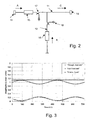
- Figure 3 illustrates the addition of two sinusoidal waves, as an example of implementation of the embodiment of figure 2, with modulation indexes which are inversely proportional to their average powers with a ratio of 1 to 8. It can be observed that the resulting wave has no amplitude modulation. It is to be noted that the modulation indexes in figure 3 are in fact exaggerated in comparison to the values used in practice, only with the purpose of providing a clear illustration of the modulation scheme itself and it is in no way to be construed as a limiting feature of the present invention.
- optical power taps 17 and 18 may be used at appropriate points in the branching unit. In the example shown in figure 2, both taps 17 and 18 are located before the port of junction between the branch and the trunk.
- the optical power being tapped off the branch line is detected by optical PIN diodes and converted to electrical signal, which is input to the supervisory modulation control electronics.
- the optical power taps, 17 and 18, can thus be used to measure the optical powers of the add and the straight-through wavelengths which are used as indicative parameters for determining the modulation index.
- the supervisory signal can be recovered by tapping-off the WDM signal and filtering out either of the spectral bands or a single wavelength belonging to either of the two spectral bands of the signal, which are modulated in phase difference or in anti-phase. Then the supervisory information carried on this wavelength can be demodulated.
Landscapes
- Physics & Mathematics (AREA)
- Electromagnetism (AREA)
- Engineering & Computer Science (AREA)
- Computer Networks & Wireless Communication (AREA)
- Signal Processing (AREA)
- Optical Communication System (AREA)
Applications Claiming Priority (2)
| Application Number | Priority Date | Filing Date | Title |
|---|---|---|---|
| GBGB0324586.7A GB0324586D0 (en) | 2003-10-22 | 2003-10-22 | System and method for a supervisory signal modulation scheme using variable optical attenuators |
| GB0324586 | 2003-10-22 |
Publications (2)
| Publication Number | Publication Date |
|---|---|
| EP1526662A2 true EP1526662A2 (de) | 2005-04-27 |
| EP1526662A3 EP1526662A3 (de) | 2007-07-18 |
Family
ID=29595563
Family Applications (1)
| Application Number | Title | Priority Date | Filing Date |
|---|---|---|---|
| EP04292312A Withdrawn EP1526662A3 (de) | 2003-10-22 | 2004-09-27 | Verfahren und Vorrichtung zur Überwachungssignalmodulation mit variablem optischem Dämpfungsglied |
Country Status (4)
| Country | Link |
|---|---|
| US (1) | US7409156B2 (de) |
| EP (1) | EP1526662A3 (de) |
| JP (1) | JP4172547B2 (de) |
| GB (1) | GB0324586D0 (de) |
Families Citing this family (12)
| Publication number | Priority date | Publication date | Assignee | Title |
|---|---|---|---|---|
| DE60132639D1 (de) * | 2001-12-27 | 2008-03-13 | Pirelli Submarine Telecom Systems Italia Spa | Optisches übertragungssystem mit raman-verstärkern und einem überwachungssystem |
| ATE382999T1 (de) * | 2001-12-27 | 2008-01-15 | Pirelli Submarine Telecom Systems Italia Spa | Optisches übertragungssystem mit raman- verstärkern umfassend ein überwachungssystem |
| US7583902B2 (en) * | 2004-08-10 | 2009-09-01 | Mindspeed Technologies, Inc. | Module to module signaling utilizing amplitude modulation |
| US7542678B2 (en) * | 2004-12-30 | 2009-06-02 | Alcatel-Lucent Usa Inc. | Method and apparatus for a supervisory channel in a WDM fiber-optic communication system |
| US7917030B2 (en) * | 2007-12-03 | 2011-03-29 | Buabbud George | Fiber optic communication system with automatic line shutdown/power reduction |
| US8750341B2 (en) | 2008-01-04 | 2014-06-10 | Mindspeed Technologies, Inc. | Method and apparatus for reducing optical signal speckle |
| JP5169538B2 (ja) * | 2008-06-30 | 2013-03-27 | 富士通株式会社 | 光伝送装置、光伝送システム及び同システムの通信方法 |
| US20150117856A1 (en) * | 2013-10-30 | 2015-04-30 | Fujitsu Limited | System and method for monitoring power imbalance induced by polarization-dependent loss |
| CN104506239B (zh) * | 2014-11-28 | 2017-06-27 | 北京百度网讯科技有限公司 | 光模块以及用于光模块的信息传输方法 |
| JP2019092117A (ja) * | 2017-11-16 | 2019-06-13 | 住友電気工業株式会社 | 光送信器の制御方法 |
| CN110661575A (zh) * | 2019-09-20 | 2020-01-07 | 武汉光迅科技股份有限公司 | 一种直调光发射机 |
| CN111277926B (zh) * | 2020-01-21 | 2021-09-21 | 中通服创立信息科技有限责任公司 | 一种无源业务验真方法 |
Family Cites Families (11)
| Publication number | Priority date | Publication date | Assignee | Title |
|---|---|---|---|---|
| US5532769A (en) * | 1994-03-31 | 1996-07-02 | Nidek Co., Ltd. | Ophthalmologic alignment device with automatic alignment means |
| JP3373332B2 (ja) | 1995-05-26 | 2003-02-04 | Kddi株式会社 | プリエンファシス方式光波長多重通信方法および装置 |
| JPH10224306A (ja) * | 1997-01-31 | 1998-08-21 | Fujitsu Ltd | 光伝送システム |
| JP3440872B2 (ja) * | 1999-05-07 | 2003-08-25 | 日本電気株式会社 | 光伝送システムにおける監視信号転送装置 |
| JP4769365B2 (ja) * | 2001-03-29 | 2011-09-07 | キヤノン株式会社 | 眼科装置、及びそのオートアライメント方法 |
| CA2444965A1 (en) | 2001-04-30 | 2002-11-07 | Pirelli Submarine Telecom Systems Italia S.P.A. | Optical transmission system comprising a supervisory system |
| GB0130214D0 (en) | 2001-12-18 | 2002-02-06 | Cit Alcatel | Supervisory signalling for optical communications equipment |
| DE60132639D1 (de) * | 2001-12-27 | 2008-03-13 | Pirelli Submarine Telecom Systems Italia Spa | Optisches übertragungssystem mit raman-verstärkern und einem überwachungssystem |
| ATE382999T1 (de) * | 2001-12-27 | 2008-01-15 | Pirelli Submarine Telecom Systems Italia Spa | Optisches übertragungssystem mit raman- verstärkern umfassend ein überwachungssystem |
| JPWO2003079584A1 (ja) * | 2002-03-19 | 2005-07-21 | 富士通株式会社 | ラマン増幅を用いた光ファイバ伝送のための方法及びシステム |
| FR2838901B1 (fr) * | 2002-04-18 | 2005-04-29 | Cit Alcatel | Procede et systeme de controle de la transmission de signaux optiques |
-
2003
- 2003-10-22 GB GBGB0324586.7A patent/GB0324586D0/en not_active Ceased
-
2004
- 2004-09-27 EP EP04292312A patent/EP1526662A3/de not_active Withdrawn
- 2004-10-08 JP JP2004295661A patent/JP4172547B2/ja not_active Expired - Fee Related
- 2004-10-21 US US10/968,888 patent/US7409156B2/en not_active Expired - Fee Related
Also Published As
| Publication number | Publication date |
|---|---|
| JP2005130492A (ja) | 2005-05-19 |
| JP4172547B2 (ja) | 2008-10-29 |
| US20050089325A1 (en) | 2005-04-28 |
| US7409156B2 (en) | 2008-08-05 |
| GB0324586D0 (en) | 2003-11-26 |
| EP1526662A3 (de) | 2007-07-18 |
Similar Documents
| Publication | Publication Date | Title |
|---|---|---|
| EP0703678B1 (de) | Leistungsüberwachung und Fehlerortung in optischen Übertragungssystemen | |
| US6259553B1 (en) | Optical communication system and optical amplifier | |
| JP3739453B2 (ja) | 光増幅器及び該光増幅器を備えた光通信システム | |
| EP0896444B1 (de) | Fernüberwachung eines optischen Übertragungssystems mittels Leitungsüberwachungssignale | |
| US7409156B2 (en) | System and method for a supervisory signal modulation scheme using variable optical attenuators | |
| JPH09116492A (ja) | 波長多重光増幅中継伝送方法およびその装置 | |
| EP0499388B1 (de) | Bidirektionelle optische Faserübertragungsstrecke mit einem Verstärker | |
| EP0911994B1 (de) | Überwachung der optischen Signalleistung mit einem Signaturbitmuster in WDM Systemen | |
| US6414775B1 (en) | Method and apparatus for measuring gain shape in an optical repeater using FM modulation | |
| WO2010072423A1 (en) | Identifying a characteristic of a mesh network | |
| EP1596511A1 (de) | Spektrales Neigungsregelungssystem and -verfahren eines optischen Mediums | |
| US5949925A (en) | Method, device, and system for optical modulation in wavelength division multiplexing | |
| JP2004221968A (ja) | 光伝送方式 | |
| US6211981B1 (en) | Optical wavelength multiplex transmission system using repeaters | |
| US7123835B2 (en) | Method and system for increasing the capacity and spectral efficiency of optical transmission | |
| US6583905B1 (en) | Apparatus and method for reducing SPM/GVD in optical systems | |
| EP0622913A1 (de) | Vorrichtung für optische Übertragung mit direkter Modulation des Senders und optischer Filterung beim Empfänger | |
| EP0963066B1 (de) | Vorrichtung und Verfahren zur Verminderung des Interaktion zwischen Eigenphasenmodulation und Gruppengeschwindkeitsdispersion in optischen Systemen | |
| EP1633062A1 (de) | Modulation mit niedrigem Übersprechen in einem optischen Kommunikationssystem | |
| JP3917605B2 (ja) | 光通信システム及び光増幅器 | |
| CA2273469A1 (en) | Apparatus and method for reducing spm/gvd in optical systems | |
| KR20000006138A (ko) | 광채널분석기를구비하는파장분할다중방식의통신시스템 | |
| MXPA98006382A (en) | Verification at distance of an optical transmission system using signals of verification of the li | |
| JPH06152521A (ja) | 周波数分割多重光伝送システム |
Legal Events
| Date | Code | Title | Description |
|---|---|---|---|
| PUAI | Public reference made under article 153(3) epc to a published international application that has entered the european phase |
Free format text: ORIGINAL CODE: 0009012 |
|
| AK | Designated contracting states |
Kind code of ref document: A2 Designated state(s): AT BE BG CH CY CZ DE DK EE ES FI FR GB GR HU IE IT LI LU MC NL PL PT RO SE SI SK TR |
|
| AX | Request for extension of the european patent |
Extension state: AL HR LT LV MK |
|
| RAP1 | Party data changed (applicant data changed or rights of an application transferred) |
Owner name: ALCATEL LUCENT |
|
| PUAL | Search report despatched |
Free format text: ORIGINAL CODE: 0009013 |
|
| AK | Designated contracting states |
Kind code of ref document: A3 Designated state(s): AT BE BG CH CY CZ DE DK EE ES FI FR GB GR HU IE IT LI LU MC NL PL PT RO SE SI SK TR |
|
| AX | Request for extension of the european patent |
Extension state: AL HR LT LV MK |
|
| 17P | Request for examination filed |
Effective date: 20080118 |
|
| AKX | Designation fees paid |
Designated state(s): AT BE BG CH CY CZ DE DK EE ES FI FR GB GR HU IE IT LI LU MC NL PL PT RO SE SI SK TR |
|
| 17Q | First examination report despatched |
Effective date: 20090811 |
|
| STAA | Information on the status of an ep patent application or granted ep patent |
Free format text: STATUS: THE APPLICATION IS DEEMED TO BE WITHDRAWN |
|
| 18D | Application deemed to be withdrawn |
Effective date: 20091222 |