EP1526515B1 - Hard disk drive - Google Patents
Hard disk drive Download PDFInfo
- Publication number
- EP1526515B1 EP1526515B1 EP04020067A EP04020067A EP1526515B1 EP 1526515 B1 EP1526515 B1 EP 1526515B1 EP 04020067 A EP04020067 A EP 04020067A EP 04020067 A EP04020067 A EP 04020067A EP 1526515 B1 EP1526515 B1 EP 1526515B1
- Authority
- EP
- European Patent Office
- Prior art keywords
- slider
- hard disk
- bias voltage
- slider body
- component
- Prior art date
- Legal status (The legal status is an assumption and is not a legal conclusion. Google has not performed a legal analysis and makes no representation as to the accuracy of the status listed.)
- Expired - Lifetime
Links
- 238000013461 design Methods 0.000 claims description 24
- 230000008859 change Effects 0.000 claims description 8
- 230000004044 response Effects 0.000 description 22
- 239000000314 lubricant Substances 0.000 description 17
- 239000000725 suspension Substances 0.000 description 16
- 239000000463 material Substances 0.000 description 13
- 238000000034 method Methods 0.000 description 11
- 230000005520 electrodynamics Effects 0.000 description 10
- 238000012360 testing method Methods 0.000 description 10
- 230000005684 electric field Effects 0.000 description 9
- 239000003990 capacitor Substances 0.000 description 7
- 239000000523 sample Substances 0.000 description 7
- 238000006073 displacement reaction Methods 0.000 description 3
- 230000005686 electrostatic field Effects 0.000 description 3
- 239000004020 conductor Substances 0.000 description 2
- 230000008878 coupling Effects 0.000 description 2
- 238000010168 coupling process Methods 0.000 description 2
- 238000005859 coupling reaction Methods 0.000 description 2
- 238000012544 monitoring process Methods 0.000 description 2
- 230000003287 optical effect Effects 0.000 description 2
- 238000000926 separation method Methods 0.000 description 2
- 229910000531 Co alloy Inorganic materials 0.000 description 1
- 238000005411 Van der Waals force Methods 0.000 description 1
- 230000000712 assembly Effects 0.000 description 1
- 238000000429 assembly Methods 0.000 description 1
- 230000015556 catabolic process Effects 0.000 description 1
- 238000011109 contamination Methods 0.000 description 1
- 238000006731 degradation reaction Methods 0.000 description 1
- 238000001514 detection method Methods 0.000 description 1
- 238000010348 incorporation Methods 0.000 description 1
- 239000002245 particle Substances 0.000 description 1
- 230000035699 permeability Effects 0.000 description 1
- 239000007787 solid Substances 0.000 description 1
- 238000010408 sweeping Methods 0.000 description 1
Images

Classifications
-
- G—PHYSICS
- G11—INFORMATION STORAGE
- G11B—INFORMATION STORAGE BASED ON RELATIVE MOVEMENT BETWEEN RECORD CARRIER AND TRANSDUCER
- G11B5/00—Recording by magnetisation or demagnetisation of a record carrier; Reproducing by magnetic means; Record carriers therefor
- G11B5/48—Disposition or mounting of heads or head supports relative to record carriers ; arrangements of heads, e.g. for scanning the record carrier to increase the relative speed
- G11B5/58—Disposition or mounting of heads or head supports relative to record carriers ; arrangements of heads, e.g. for scanning the record carrier to increase the relative speed with provision for moving the head for the purpose of maintaining alignment of the head relative to the record carrier during transducing operation, e.g. to compensate for surface irregularities of the latter or for track following
- G11B5/60—Fluid-dynamic spacing of heads from record-carriers
- G11B5/6005—Specially adapted for spacing from a rotating disc using a fluid cushion
-
- G—PHYSICS
- G11—INFORMATION STORAGE
- G11B—INFORMATION STORAGE BASED ON RELATIVE MOVEMENT BETWEEN RECORD CARRIER AND TRANSDUCER
- G11B5/00—Recording by magnetisation or demagnetisation of a record carrier; Reproducing by magnetic means; Record carriers therefor
- G11B5/127—Structure or manufacture of heads, e.g. inductive
- G11B5/31—Structure or manufacture of heads, e.g. inductive using thin films
- G11B5/3103—Structure or manufacture of integrated heads or heads mechanically assembled and electrically connected to a support or housing
- G11B5/3106—Structure or manufacture of integrated heads or heads mechanically assembled and electrically connected to a support or housing where the integrated or assembled structure comprises means for conditioning against physical detrimental influence, e.g. wear, contamination
-
- G—PHYSICS
- G11—INFORMATION STORAGE
- G11B—INFORMATION STORAGE BASED ON RELATIVE MOVEMENT BETWEEN RECORD CARRIER AND TRANSDUCER
- G11B5/00—Recording by magnetisation or demagnetisation of a record carrier; Reproducing by magnetic means; Record carriers therefor
- G11B5/48—Disposition or mounting of heads or head supports relative to record carriers ; arrangements of heads, e.g. for scanning the record carrier to increase the relative speed
- G11B5/4806—Disposition or mounting of heads or head supports relative to record carriers ; arrangements of heads, e.g. for scanning the record carrier to increase the relative speed specially adapted for disk drive assemblies, e.g. assembly prior to operation, hard or flexible disk drives
- G11B5/4826—Mounting, aligning or attachment of the transducer head relative to the arm assembly, e.g. slider holding members, gimbals, adhesive
-
- G—PHYSICS
- G11—INFORMATION STORAGE
- G11B—INFORMATION STORAGE BASED ON RELATIVE MOVEMENT BETWEEN RECORD CARRIER AND TRANSDUCER
- G11B5/00—Recording by magnetisation or demagnetisation of a record carrier; Reproducing by magnetic means; Record carriers therefor
- G11B5/48—Disposition or mounting of heads or head supports relative to record carriers ; arrangements of heads, e.g. for scanning the record carrier to increase the relative speed
- G11B5/4806—Disposition or mounting of heads or head supports relative to record carriers ; arrangements of heads, e.g. for scanning the record carrier to increase the relative speed specially adapted for disk drive assemblies, e.g. assembly prior to operation, hard or flexible disk drives
- G11B5/4873—Disposition or mounting of heads or head supports relative to record carriers ; arrangements of heads, e.g. for scanning the record carrier to increase the relative speed specially adapted for disk drive assemblies, e.g. assembly prior to operation, hard or flexible disk drives the arm comprising piezoelectric or other actuators for adjustment of the arm
-
- G—PHYSICS
- G11—INFORMATION STORAGE
- G11B—INFORMATION STORAGE BASED ON RELATIVE MOVEMENT BETWEEN RECORD CARRIER AND TRANSDUCER
- G11B5/00—Recording by magnetisation or demagnetisation of a record carrier; Reproducing by magnetic means; Record carriers therefor
- G11B5/48—Disposition or mounting of heads or head supports relative to record carriers ; arrangements of heads, e.g. for scanning the record carrier to increase the relative speed
- G11B5/58—Disposition or mounting of heads or head supports relative to record carriers ; arrangements of heads, e.g. for scanning the record carrier to increase the relative speed with provision for moving the head for the purpose of maintaining alignment of the head relative to the record carrier during transducing operation, e.g. to compensate for surface irregularities of the latter or for track following
- G11B5/60—Fluid-dynamic spacing of heads from record-carriers
- G11B5/6005—Specially adapted for spacing from a rotating disc using a fluid cushion
- G11B5/6011—Control of flying height
- G11B5/6035—Control of flying height using electrostatic forces
-
- G—PHYSICS
- G11—INFORMATION STORAGE
- G11B—INFORMATION STORAGE BASED ON RELATIVE MOVEMENT BETWEEN RECORD CARRIER AND TRANSDUCER
- G11B5/00—Recording by magnetisation or demagnetisation of a record carrier; Reproducing by magnetic means; Record carriers therefor
- G11B5/40—Protective measures on heads, e.g. against excessive temperature
Definitions
- the present invention relates to hard disk drives (HDDs).
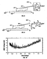
- FIG 1 shows an exemplary hard disk drive (HDD) 100 having a dual-stage servo system for positioning a slider assembly 101 over a selected concentric data information track on a magnetic disk 102 for writing data to and/or reading data from the selected track.
- the dual-stage servo system of HDD 100 includes a primary actuator 104, such as a rotary voice-coil motor (VCM), for coarse positioning an actuator arm 105 and a read/write head suspension 106, and a secondary actuator (not shown in Figure 1 ), such as a microactuator or micropositioner, for fine positioning slider assembly 101 over a selected track.
- a microactuator as used herein, is a small actuator that is placed between a suspension and a slider and moves the slider relative to the suspension.
- Slider assembly 101 includes a read/write head (not shown in Figure 1 ) having a read element, such as a Giant Magnetoresistive (GMR) element, and a write element that respectively read data from and write data to a selected data track. While HDD 100 is shown as having only a single magnetic disk 102, HDDs typically have a plurality of stacked, commonly rotated, rigid magnetic disks and a corresponding number of actuator arms, read/write head suspensions, secondary actuators and slider assemblies.
- a read/write head not shown in Figure 1
- a read element such as a Giant Magnetoresistive (GMR) element
- GMR Giant Magnetoresistive
- Figure 2 depicts an electrostatic field that can exist between a slider body 201 and a hard disk 202 of a hard disk drive.
- a suspension supporting slider body 201 is not shown.
- disk 202 rotates, disk 202 moves from right to left with respect to slider body 201, as indicated by arrow 203.
- Enlargement 204 of the slider-disk interface shows lines representing an electric field 205 that is formed from a potential difference between slider body 201 and disk 202.
- Electric field 205 exists between slider body 201 and disk 202 all along the length of slider body 202, but is only indicated in enlargement 204 because the intensity of electric field 205 is greatest at the trailing edge of slider body 201.
- one source for the potential difference is the contact potential that originates from the conducting portions of the slider body and disk having different work functions and from tribocharging of the non-conducting portions.
- Another source for the potential difference is tribocharging associated with the spindle motor bearing, which can shift the disk potential significantly from ground potential.
- Electric field 205 between slider body 201 and disk 202 generates an electrostatic force that acts the on the surfaces of slider body 201 and disk 202 within the slider-disk interface.
- the electrostatic force associated with electric field 205 depends on the applied voltage and the other physical parameters of the slider-disk interface. As the potential difference between the slider body and the disk increases, the slider flying height is reduced from the design flying height of the slider.
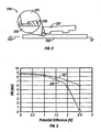
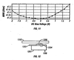
- Figure 3 shows the flying height (FH) for a high-pitch air bearing design and a low-pitch air bearing design as a function slider-disk potential difference.
- Both air bearing designs have a design fly height 9 nm above a disk.
- the high-pitch slider has a dynamic pitch angle of 180 ⁇ rad.
- the low-pitch slider has a dynamic pitch angle of 70 ⁇ rad at a flying height of 9 nm.
- Curve 301 represents the flying height for the high-pitch slider as a function of the slider-disk potential difference.
- Curve 302 is the flying height for a low-pitch slider as a function of the slider-disk potential difference.
- the low-pitch slider is more sensitive to an applied DC electric field than a high-pitch slider because a low pitch design has on average a smaller separation distance than a high-pitch design when the electrostatic force is integrated over the slider.
- the flying height is reduced by about 0.5 nm for a potential difference of about 0.5 V for both the high-pitch and low-pitch air bearing designs.
- the value of the flying height at 2.5 V for the low-pitch slider is extrapolated to 0 nm because contact occurs at 2.5 V.
- the disks are lubricated using perfluoropolyether-type lubricants having long polar chains, such as Fomblin Z-DOL.
- the polarity of the lubricant in the presence of an electrostatic field at the head-disk interface can cause lubricant to be removed from the disk surface and possibly be depleted from the disk surface.
- the removed lubricant is usually picked up by the slider and can lead to drive failure. Consequently, as lubricant is removed, the lubricant is attracted to slider body 201 by the polarity of the lubricant and the electrostatic force and becomes concentrated in areas on slider body 201 that have a high electric field, such as the trailing edge of the slider body.
- the lubricant can form droplets that can lead to read/write errors when the droplets of lubricant enter the headdisk interface.
- Electric field 205 can also attract particles onto slider body 201 that can lead to scratches on both slider body 201 and the surface of disk 202.
- Yet another potential problem that is caused by the electrostatic force is an increased vibrational coupling between slider body 201 and disk 202, leading to larger modulations of the slider-disk spacing.
- a glide test system includes a glide test head supportable over the disc, the glide test head having a negative-pressure air bearing slider and a contact sensor which outputs a signal when the glide test head contacts a feature of the disc surface.
- the glide test head and the disc are characterized as opposing plates of a variable capacitor with a dielectric layer therebetween including at least a layer of air supporting the glide test head.
- a voltage source operably coupled to the glide test head and the disc, applies a fly height control voltage across the capacitor to adjust the fly height of the glide test head.
- the disc surface preferably comprises a data region configured to magnetically store data as the disc is rotated and a texturized landing zone configured to support the disc drive read/write head when the disc is stopped.
- the voltage source accordingly applies a first fly height control voltage to maintain the glide test head at a first glide distance over the data region and a second fly height control voltage to maintain the glide test head at a second, greater glide distance over the landing zone
- slider-to-disk spacing can be controlled by adjusting a DC bias applied to the slider-disk interface. See, for example, US 6,005,736 ; US 6,529,342 and US 6,366,416 .
- the present invention provides a technique for determining the optimum bias voltage that should be applied between a slider body and a disk for eliminating an electrical potential difference that exists between the slider body and the disk, such as a contact potential. More particularly, the present invention relates to a technique for detecting and eliminating an electrical potential difference between a slider body and a disk surface of an HDD, such as a contact potential caused by material differences between the slider and the disk or a potential generated by tribocharging.
- the electric potential at the head/disk interface is actively controlled for wear and durability control.
- a disk drive eliminating an electrical potential difference between a slider body and a hard disk of a hard disk drive.
- a flying-height spacing of the slider body between the slider body and the hard disk is detected.
- a predetermined bias voltage is applied between the slider body and the hard disk that includes a DC component and an AC component and that is based on the detected flying-height spacing of the slider body.
- One aspect of the present invention provides that the flying height spacing of the slider body is detected based on determining a minimum slider-to-disk clearance change from a design flying height of the slider at a frequency of the AC component as the DC component of the predetermined bias voltage is varied.
- One embodiment of the present invention detects the flying-height spacing of the slider body using a Laser Doppler Vibrometer. Another embodiment of the present invention detects the flying-height spacing of the slider body based on a magnitude of magnetic readback signal that is sensed by a read element on the slider body at the frequency of the AC component as a magnitude of the DC component is varied.
- the AC component can be a swept-frequency AC signal or a single-frequency AC signal.
- Yet another embodiment of the present invention detects the flying-height of the slider body based on a minimum variation of current that flows on and off the slider body as the DC component of the bias voltage is varied.
- Still another embodiment of the present invention detects the flying-height spacing of the slider body is based on a minimum resistance of a magnetoresistive element as the DC component is varied.
- a further embodiment of the present invention detects the flying-height spacing of the slider body based on an output of a piezoelectric sensor or an acoustic emission sensor sensing contact between the slider body and the hard disk as the DC component is varied.
- the magnitude of the predetermined voltage can be controlled based on the detected flying-height spacing of the slider body, such as by determining a minimum slider-to-disk clearance change from the design flying height of the slider as the DC component is varied, or by determining a minimum interference between the slider body and the hard disk as the DC component is varied.
- the magnitude of the predetermined voltage can be controlled so that an amplitude of a variation of the flying-height spacing times a sine of a phase difference of the flying-height spacing at a frequency of the AC component is a minimum.
- the present invention provides a technique for determining the optimum bias voltage that should be applied between a slider body and a disk for eliminating an electrical potential difference that exists between the slider body and the disk, such as a contact potential caused by tribocharging or by the material differences of slider and disk.
- an electrical potential difference that exists between the slider body and the disk, such as a contact potential caused by tribocharging or by the material differences of slider and disk.
- a bias voltage having a DC component plus a swept-frequency AC component is applied between a slider body and a disk, and the minimum electrodynamic response of the slider to the first harmonic of the swept-frequency AC component, which is preferably is within the range of the air bearing (i.e., 50 kHz to 500 kHz), is detected as the magnitude of the DC component is varied for determining the contact voltage between the slider and the disk.
- the AC component of the bias voltage has a fixed frequency, which is preferably within the range of the air bearing (i.e., 50 kHz to 500 kHz).
- the range that the magnitude of the DC component can be varied can be about -5.0 V DC to about +5.0 V DC with a current limitation of about 1 ⁇ A.
- the magnitude of the AC component should preferably not exceed about 300 mV
- a first aspect of the present invention utilizes the slider body and a hard disk as a Kelvin probe to determine the optimum DC bias voltage that should be applied between the slider body and the hard by detecting the minimum electrodynamic response of the slider to the first harmonic of the AC frequency of the AC component of the bias voltage as the DC component of the bias voltage is varied.
- the minimum electrodynamic response of the slider can be detected using an external Laser Doppler Vibrometer (LDV) or laser interferometer and/or by monitoring the magnitude of a readback signal at the frequency of the AC component of the bias voltage.
- LDV Laser Doppler Vibrometer
- a second aspect of the invention provides that the optimum DC bias voltage that should be applied between a slider body and a disk is determined by detecting the magnitude of the current fluctuations that flow on and off of the slider as the DC bias voltage is varied.
- a third aspect of the present invention provides that the optimum DC bias voltage that should be applied between a slider body and a disk is determined by detecting interference between the slider and the disk. It should be understood that throughout the description of the present invention, phrases such as “maximum slider-disk spacing” or “maximum flying height of the slider” should be understood to mean the design flying height of the slider.
- Figure 4 depicts the general concept of all embodiments of the present invention for determining the optimum DC bias voltage that should be applied to a slider body for eliminating an electrical potential difference between a slider body 401 and a hard disk 402.
- a suspension 404 supports slider body 401. While disk 402 is indicated as being at ground potential, it should be understood that disk 402 can have a potential difference relative to the rest of the HDD or slider body, such as that caused by tribocharging of the spindle motor bearing.
- the embodiments would also work when the DC and AC voltages were applied to the disk rather than to the slider body.
- a DC bias voltage V DC plus an AC bias voltage V 0 sin ⁇ t are applied to slider body 401 through suspension 404. At a given AC frequency, the DC bias voltage is varied to determine the minimum amount of slider/disk interference.
- the first two embodiments of the present invention utilize the slider body and the hard disk as a Kelvin probe to determine the optimum DC bias voltage that should be applied between the slider and the hard disk for eliminating an electrical potential difference that exists between the slider body and the disk, such as a contact potential caused by tribocharging.
- a Kelvin probe is a capacitor having one plate vibrating at an AC frequency and the other plate fixed, similar to a slider body and a hard disk.
- the optimum DC bias voltage that should be applied between the slider body and the hard disk is determined by detecting the minimum electrodynamic response of the slider to the first harmonic of the AC frequency of the AC component of the bias voltage as the DC component of the bias voltage is varied.
- ⁇ 0 ⁇ r is the permeability of the dielectric between the plates
- A is the area of the plates
- d is the distance of separation of the plates
- V is the potential difference between the plates.
- the potential difference V between the plates is, for the present invention, the sum of an externally applied bias voltage and an internal contact potential V contact .
- Contact potential V contact is the potential difference between the two plates in the absence of an applied voltage and originates from the plates being made of different materials having different work functions. See, for example, N.W. Ashcroft et al., Chapter 18, Solid State Physics, Holt, Rinehart and Winston, New York, 1976.
- the work function of a material is the amount of energy that is needed for releasing electrons from the surface of the material, and is related to the optical, electrical and mechanical properties of the material.
- the conducting part of the slider body is typically sintered Al 2 O 3 -TiC and the conducting part of the disk is typically a cobalt-based alloy magnetic layer.
- the respective work functions for the materials of the slider body and the conducting part of the disk are further modified by overcoats and lubricants that are deposited for tribology protection.
- the first and last terms within the square brackets in Eq. (2) represent the DC response to the applied bias voltage V bias
- the second term represents the first harmonic response to V bias
- the third term in square brackets represents the second harmonic response to V bias .
- the second harmonic term is independent of the applied DC voltage.
- the optimum DC component of the applied bias voltage V bias can be detected when the first harmonic electrodynamic response of the slider to the AC component of the applied bias voltage V bias equals zero (i.e., no slider vibration at the first harmonic of the applied AC component).
- the first embodiment of the present invention provides a technique that is applicable when the disk drive is open. All of the other embodiments of the present invention that will be described herein are applicable when the disk drive is sealed.
- a Laser Doppler Vibrometer (LDV) that is external to the disk drive is used for determining the minimum slider-to-disk clearance change from the design flying height of the slider as the applied bias voltages are varied.
- Figure 5 depicts a system 500 for measuring the flying height of a slider with respect to a disk using an LDV.
- a slider body 501 is suspended above a hard disk 502 by a suspension 504 as disk 502 moves from right to left with respect to slider body 501, as indicated by arrow 503.
- a bias voltage having a DC component V DC plus an AC component V 0 sin ⁇ t is output from an AC/DC power supply 706 and is applied between slider body 501 and disk 502.
- the bias voltage is applied to slider body 501 through suspension 504.
- the bias voltage is varied under the control of computer 507.
- An LDV 508 measures a velocity of the trailing edge of slider body 501.
- a lockin amplifier 509 measures first and second harmonics of the LDV velocity signal at the AC driving frequency, which is typically at an air bearing frequency. The first harmonic of the AC driving frequency is minimized when the DC bias voltage cancels the contact potential between slider body 501 and disk 502.
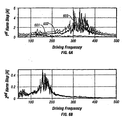
- Figures 6A and 6B respectively shows the first and second harmonic response of an exemplary slider at the air bearing frequency range (50 kHz to 500 kHz) for DC bias voltages of -0.5 V, 0 V and +0.5 V DC.
- the magnitude of the AC component of the applied bias voltage for all DC bias voltages was 100 mV.
- Curve 601 represents the first harmonic response of the slider for an applied bias voltage having a DC component of +0.5 V.
- Curve 602 represents the first harmonic response of the slider for an applied bias voltage having a DC component of 0 V DC.
- Curve 603 represents the first harmonic response of the slider for an applied bias voltage having a DC component of -0.5 V DC.
- the curves representing the respective responses for the second harmonic of the applied bias voltage remain unchanged for the different applied bias voltages and are essentially indistinguishable from each other. Consequently, the second harmonic responses are not separately indicated. Note that the second pitch mode frequency at ⁇ 320 kHz is strongly excited by the AC component of the applied bias voltage, while the first pitch at ⁇ 120 kHz is weakly excited.
- the contact potential could also be determined simply by monitoring the value of the DC component of the applied bias voltage and determining when the electrodynamic response to the first harmonic of a single-frequency AC component of the applied bias voltage is minimized.
- the frequency of the single-frequency AC component should be preferably at a mechanical resonance, such as a suspension resonance, an air bearing resonance or a slider body resonance.
- a high signal-to-noise ratio is achieved when the frequency is near the pitch 2 mode frequency of a slider air bearing.
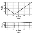
- Figures 7A and 7B respectively show the first harmonic displacement and phase of an exemplary slider air bearing resonance as a function of DC bias voltage for a 290 kHz AC bias voltage having a magnitude of about 100 mV.
- Figure 7A shows that the DC component of the applied bias voltage is about -0.4 V DC when the electrodynamic response at the first harmonic of a single-frequency AC component of the applied bias voltage is minimized.
- the minimum slider-to-disk clearance change from the design flying height of the slider based on a relative magnitude of a magnetic readback signal sensed by the read element on slider body 401, shown in Figure 4 . That is, when slider body 401 is correctly positioned over a selected track, the maximum magnitude of the readback signal varies as the applied bias voltages are varied. In particular, the maximum magnitude of the readback signal varies inversely to the flying height of the slider. Thus, when the flying height of the slider is a maximum, that is, at the design flying height of the slider, the maximum magnitude of the readback signal will be a relative minimum.
- the maximum magnitude of the readback signal will be greater than when the slider is at the design flying height.
- the flying height will be changed from the design flying height by about 0.1 nm or less for a contact potential of between 0 V DC and 0.5 V DC. Consequently, a change in the magnitude of the readback signal is likely not detectable.
- SNR Signal-to-Noise
- the amplitude of the readback signal must be filtered to be exactly the frequency of the AC component. When a swept-frequency AC component is used, then a frequency selective device, such as a lockin amplifier, can be used.
- the maximum slider-disk spacing can be identified based on the Position Error Signal (PES) that is generated in a well-known manner.
- PES Position Error Signal
- a third embodiment of the present invention provides that the optimum DC bias voltage that should be applied to the slider body is detected by identifying the minimum current variation that flows on and off the slider as the DC bias voltage is varied.
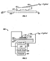
- Figure 8 depicts a first configuration for the third embodiment of the present invention for determining the optimum DC bias voltage that should be applied to a slider body for eliminating an electrical potential difference between a slider body 801 and a hard disk 802. As disk 802 rotates, disk 802 moves from right to left with respect to slider body 801, as indicated by arrow 803. A suspension 804 supports slider body 801. While disk 802 is indicated as being at ground potential, it should be understood that disk 802 can include an electrical potential relative to the HDD.
- a current sense circuit 805 is coupled to slider body through suspension 804.
- Current sense circuit 805 includes an amplifier 806 that is configured in an inverting topology with feedback resistor R. The bias voltage is applied to the non-inverting input of amplifier 806.
- the current i (dC/dt)(V c + V DC ) + CdV C /dt, in which C is the slider-disk capacitance and V c is the contact potential.
- dV C /dt ⁇ 0
- the current i comes mainly from the variation of slider-disk capacitance, which varies due to changes in flying height and pitch.
- FIG. 9 An alternative configuration for the third embodiment of the present invention is shown in Figure 9 , which depicts a slider body 901, a hard disk 902 and a current sense circuit 905 for measuring only the AC component in the variation in current i.
- a suspension 904 supports slider body 901. While disk 902 is indicated as being at ground potential, it should be understood that disk 902 can include an electrical potential relative to the HDD.
- Current sense circuit 905 includes an amplifier 906 that is configured in an inverting topology with resistors R 2 and R 3 setting the gain.
- a capacitor C 1 DC-isolates amplifier 907 from slider body 901 and bias voltage source V DC . Resistor R 1 isolates bias voltage source V DC from capacitor C 1
- the fourth and fifth embodiments of the present invention related to determining the optimum DC bias voltage that should be applied between a slider body and a hard disk by detecting the least amount of interference between the slider body and the hard disk.
- the AC component of the applied bias voltage can be used to create a slider vibration that is sufficiently large to induce contact between the slider body and the hard disk.
- the AC component of the applied bias voltage would not be necessary to induce contact between the slider body and the hard disk.
- a fifth embodiment of the present invention provides that the optimum DC bias voltage that should be applied between a slider body and a disk is detected by identifying the maximum slider-disk spacing by using a piezoelectric (PZT) sensor.
- FIG 12 shows a side view of an exemplary arrangement of a slider body 1201, a suspension 1202 and a flexure 1203 having an exemplary piezoelectric pressure sensor 1204 for sensing pressure that flexure 1203 exerts against suspension 1202 at a dimple 1205 as slider body 1201 contacts a disk (not shown) at 1206.
- Piezoelectric pressure sensor 1204 is fabricated as an integral part of flexure 1203.
- Piezoelectric pressure sensor 1204 detects head-disk interference (HDI) when slider body 1201 contacts a disk (not shown in Figure 12 ).
- HDI head-disk interference
- the output of piezoelectric pressure sensor 1204 is a minimum.
- an acoustic emission (AE) sensor can be used instead of a piezoelectric pressure sensor, in which case detection of the maximum flying height of the slider would occur when the output of the acoustic emission sensor is a minimum.
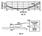
- Figure 13 shows the output of an AE sensor for an exemplary slider as a function of an applied bias voltage having a DC component.
- Curve 1301 represents the output of the AE sensor after 20 minutes.
- Curve 1302 represents the output of the AE sensor after 17 hours.
- the Kelvin probe-based embodiments of the present invention provide a superior technique for determining the optimum DC bias voltage that should be applied between a slider body and a hard disk than the embodiments of the present invention that are based on detecting a minimum interference between a slider body and a hard disk.
- the bias voltage applied between a slider body and a disk can be controlled by a feedback loop that adjusts the DC component V DC of the applied bias voltage to keep Asin ⁇ near zero, in which A is the amplitude of the slider-disk spacing variation at ⁇ and ⁇ is the phase difference between the slider-disk spacing variation at ⁇ and the AC component V 0 sin ⁇ t of the applied bias voltage.
- a control loop that determines the optimum V DC bias voltage that should be applied between a slider body and a disk can be based on any of the five alterative embodiments of the present invention for determining the optimum DC bias voltage that should be applied to a slider body for eliminating an electrical potential difference between a slider body and a hard disk.
- Figure 14 depicts an exemplary control system 1400 for applying the optimum DC bias voltage between a slider body 1401 and a hard disk 1402 according to the present invention.
- Control system 1400 includes a sensor system 1405 that senses the electrodynamic response of slider body 1401 to an applied AC bias voltage and/or a level of interference between slider body 1401 and hard disk 1402 using any of the techniques described in connection with the present invention.
- Sensor system 1405 outputs a control signal that corresponds to the sensed electrodynamic response of slider body 1401 and/or the level of interference between slider body 1401 and hard disk 1402.
- a bias voltage source 1406 outputs a bias voltage in response to the control signal that is applied to slider body 1404.
- the techniques of the present invention can be applied to each respective slider-disk interface of an HDD individually or collectively. That is, the optimum bias voltage for each respective slider-disk interface can be detected separately. Alternatively, the optimum bias voltage for a single slider-disk interface can be detected and used for generating a bias voltage that is applied to each respective slider-disk interface. Accordingly, any of the techniques of the present invention for determining the optimum DC bias voltage that should be applied between a slider body and a hard disk described herein can be used in a control loop to control the applied DC bias voltage. Further, the techniques of the present invention can also be applied to magneto-optical drives or optical drives that contain a slider having an aperture/lens and a rotating disk.
- the present invention has been described in terms of determining an optimum bias voltage that should be applied between a slider body and a disk for eliminating an electrical potential difference that exists between the slider body and the disk, it should be understood that the Kelvin probe aspects of the present invention can be used for detecting the condition or state of a slider-disk interface as it varies over time.
- the optimum bias voltage can be determined using any of the embodiments of the present invention and used as a baseline against which subsequent detected changes in the optimum bias voltage are used for determining, for example, the amount of lubricant that is present at different areas of the disk.
- the contact potential is sensitive to fermi-level changes and to changes of the surface potential, the present invention can be used to monitor lubricant degradation or drive contamination.
Landscapes
- Engineering & Computer Science (AREA)
- Manufacturing & Machinery (AREA)
- Adjustment Of The Magnetic Head Position Track Following On Tapes (AREA)
- Manufacturing Of Magnetic Record Carriers (AREA)
- Measurement Of Length, Angles, Or The Like Using Electric Or Magnetic Means (AREA)
Description
- The present invention relates to hard disk drives (HDDs).
-
Figure 1 shows an exemplary hard disk drive (HDD) 100 having a dual-stage servo system for positioning aslider assembly 101 over a selected concentric data information track on amagnetic disk 102 for writing data to and/or reading data from the selected track. The dual-stage servo system ofHDD 100 includes aprimary actuator 104, such as a rotary voice-coil motor (VCM), for coarse positioning anactuator arm 105 and a read/writehead suspension 106, and a secondary actuator (not shown inFigure 1 ), such as a microactuator or micropositioner, for finepositioning slider assembly 101 over a selected track. A microactuator, as used herein, is a small actuator that is placed between a suspension and a slider and moves the slider relative to the suspension.Slider assembly 101 includes a read/write head (not shown inFigure 1 ) having a read element, such as a Giant Magnetoresistive (GMR) element, and a write element that respectively read data from and write data to a selected data track. While HDD 100 is shown as having only a singlemagnetic disk 102, HDDs typically have a plurality of stacked, commonly rotated, rigid magnetic disks and a corresponding number of actuator arms, read/write head suspensions, secondary actuators and slider assemblies. - As slider-to-disk spacing becomes smaller than 10 nm, electrostatic and intermolecular forces between a slider and a disk become increasingly significant. Even when a slider body and a disk are both grounded, a potential difference can exist between the slider body and the disk that can generate an electrostatic force greater than the van der Waals force. One source of the potential difference is tribocharging, or frictional electrification of non-conducting materials on the slider body. (See, for example, J.D. Kiely et al., "Tribocharging of the magnetic hard disk drive head-disk interface," Journal of Applied Physics, Vol. 91, No. 7, pp. 4631-4636, April 1, 2002.) Another source is the contact potential between the conducting materials of the slider body and the disk.
-
Figure 2 depicts an electrostatic field that can exist between aslider body 201 and ahard disk 202 of a hard disk drive. A suspension supportingslider body 201 is not shown. Asdisk 202 rotates,disk 202 moves from right to left with respect toslider body 201, as indicated byarrow 203.Enlargement 204 of the slider-disk interface shows lines representing anelectric field 205 that is formed from a potential difference betweenslider body 201 anddisk 202.Electric field 205 exists betweenslider body 201 anddisk 202 all along the length ofslider body 202, but is only indicated inenlargement 204 because the intensity ofelectric field 205 is greatest at the trailing edge ofslider body 201. As mentioned, one source for the potential difference is the contact potential that originates from the conducting portions of the slider body and disk having different work functions and from tribocharging of the non-conducting portions. Another source for the potential difference is tribocharging associated with the spindle motor bearing, which can shift the disk potential significantly from ground potential. -
Electric field 205 betweenslider body 201 anddisk 202 generates an electrostatic force that acts the on the surfaces ofslider body 201 anddisk 202 within the slider-disk interface. The electrostatic force associated withelectric field 205 depends on the applied voltage and the other physical parameters of the slider-disk interface. As the potential difference between the slider body and the disk increases, the slider flying height is reduced from the design flying height of the slider. - For example,
Figure 3 shows the flying height (FH) for a high-pitch air bearing design and a low-pitch air bearing design as a function slider-disk potential difference. Both air bearing designs have a design fly height 9 nm above a disk. The high-pitch slider has a dynamic pitch angle of 180 µrad. The low-pitch slider has a dynamic pitch angle of 70 µrad at a flying height of 9 nm.Curve 301 represents the flying height for the high-pitch slider as a function of the slider-disk potential difference.Curve 302 is the flying height for a low-pitch slider as a function of the slider-disk potential difference. The low-pitch slider is more sensitive to an applied DC electric field than a high-pitch slider because a low pitch design has on average a smaller separation distance than a high-pitch design when the electrostatic force is integrated over the slider. The flying height is reduced by about 0.5 nm for a potential difference of about 0.5 V for both the high-pitch and low-pitch air bearing designs. The value of the flying height at 2.5 V for the low-pitch slider is extrapolated to 0 nm because contact occurs at 2.5 V. - In current hard drives, the disks are lubricated using perfluoropolyether-type lubricants having long polar chains, such as Fomblin Z-DOL. The polarity of the lubricant in the presence of an electrostatic field at the head-disk interface can cause lubricant to be removed from the disk surface and possibly be depleted from the disk surface. The removed lubricant is usually picked up by the slider and can lead to drive failure. Consequently, as lubricant is removed, the lubricant is attracted to
slider body 201 by the polarity of the lubricant and the electrostatic force and becomes concentrated in areas onslider body 201 that have a high electric field, such as the trailing edge of the slider body. Once concentrated, the lubricant can form droplets that can lead to read/write errors when the droplets of lubricant enter the headdisk interface.Electric field 205 can also attract particles ontoslider body 201 that can lead to scratches on bothslider body 201 and the surface ofdisk 202. Yet another potential problem that is caused by the electrostatic force is an increased vibrational coupling betweenslider body 201 anddisk 202, leading to larger modulations of the slider-disk spacing. - An apparatus and method for evaluating surface characteristics of a recording disc prior to incorporation into a disc drive. A glide test system includes a glide test head supportable over the disc, the glide test head having a negative-pressure air bearing slider and a contact sensor which outputs a signal when the glide test head contacts a feature of the disc surface. The glide test head and the disc are characterized as opposing plates of a variable capacitor with a dielectric layer therebetween including at least a layer of air supporting the glide test head. A voltage source, operably coupled to the glide test head and the disc, applies a fly height control voltage across the capacitor to adjust the fly height of the glide test head. The disc surface preferably comprises a data region configured to magnetically store data as the disc is rotated and a texturized landing zone configured to support the disc drive read/write head when the disc is stopped. The voltage source accordingly applies a first fly height control voltage to maintain the glide test head at a first glide distance over the data region and a second fly height control voltage to maintain the glide test head at a second, greater glide distance over the landing zone
- A number of researchers have found over the past years that slider-to-disk spacing can be controlled by adjusting a DC bias applied to the slider-disk interface. See, for example,
US 6,005,736 ;US 6,529,342 andUS 6,366,416 . - Accordingly, what is needed is a technique for determining the optimum bias voltage that should be applied between a slider body and a disk for eliminating an electrical potential difference that exists between the slider body and the disk, such as a contact potential.
- This object is achieved by the hard disk drive of the independant claims. Advantageous embodiments of the invention are characterized in the sub-claims.
- The present invention provides a technique for determining the optimum bias voltage that should be applied between a slider body and a disk for eliminating an electrical potential difference that exists between the slider body and the disk, such as a contact potential. More particularly, the present invention relates to a technique for detecting and eliminating an electrical potential difference between a slider body and a disk surface of an HDD, such as a contact potential caused by material differences between the slider and the disk or a potential generated by tribocharging. In the hard disk drive of the invention the electric potential at the head/disk interface is actively controlled for wear and durability control.
- The advantages of the present invention are provided by a disk drive eliminating an electrical potential difference between a slider body and a hard disk of a hard disk drive. According to the present invention, a flying-height spacing of the slider body between the slider body and the hard disk is detected. A predetermined bias voltage is applied between the slider body and the hard disk that includes a DC component and an AC component and that is based on the detected flying-height spacing of the slider body. One aspect of the present invention provides that the flying height spacing of the slider body is detected based on determining a minimum slider-to-disk clearance change from a design flying height of the slider at a frequency of the AC component as the DC component of the predetermined bias voltage is varied. Another aspect of the present invention provides that the flying height spacing of the slider body is detected based on detecting a minimum electrodynamic response of the slider to a first harmonic of the AC frequency of the AC component as the DC component is varied. Still another aspect of the present invention provides that the flying-height of the slider body is detected based on a minimum interference between the slider body and the hard disk at a frequency of the AC component as the DC component is varied.
- One embodiment of the present invention detects the flying-height spacing of the slider body using a Laser Doppler Vibrometer. Another embodiment of the present invention detects the flying-height spacing of the slider body based on a magnitude of magnetic readback signal that is sensed by a read element on the slider body at the frequency of the AC component as a magnitude of the DC component is varied. For these embodiments of the present invention, the AC component can be a swept-frequency AC signal or a single-frequency AC signal. Yet another embodiment of the present invention detects the flying-height of the slider body based on a minimum variation of current that flows on and off the slider body as the DC component of the bias voltage is varied. Still another embodiment of the present invention detects the flying-height spacing of the slider body is based on a minimum resistance of a magnetoresistive element as the DC component is varied. A further embodiment of the present invention detects the flying-height spacing of the slider body based on an output of a piezoelectric sensor or an acoustic emission sensor sensing contact between the slider body and the hard disk as the DC component is varied.
- The magnitude of the predetermined voltage can be controlled based on the detected flying-height spacing of the slider body, such as by determining a minimum slider-to-disk clearance change from the design flying height of the slider as the DC component is varied, or by determining a minimum interference between the slider body and the hard disk as the DC component is varied. Alternatively, the magnitude of the predetermined voltage can be controlled so that an amplitude of a variation of the flying-height spacing times a sine of a phase difference of the flying-height spacing at a frequency of the AC component is a minimum.
- The present invention is illustrated by way of example and not by limitation in the accompanying figures in which like reference numerals indicate similar elements and in which:
-
Figure 1 shows an exemplary hard disk drive; -
Figure 2 depicts an electrostatic field that can exist between a slider body and a hard disk of a hard disk drive; -
Figure 3 shows the flying height for two different air bearing designs as a function slider-disk potential difference; -
Figure 4 depicts the general concept for all embodiments of the present invention for determining the optimum DC bias voltage that should be applied to a slider body for eliminating an electrical potential difference between a slider body and a hard disk; -
Figure 5 depicts a system using a Laser Doppler Vibrometer for determining the optimum bias voltage that should be applied between a slider body according to the present invention; -
Figures 6A and 6B respectively shows the first and second harmonic response of an exemplary slider at the air bearing frequency range for different DC bias voltages; -
Figures 7A and 7B respectively show the first harmonic displacement and phase of an exemplary slider as a function of DC bias voltage at a single AC frequency; -
Figure 8 depicts a first configuration of a third embodiment of the present invention for determining the optimum DC bias voltage that should be applied between a slider body and a hard disk; -
Figure 9 depicts an alternative configuration of the third embodiment of the present invention for determining the optimum DC bias voltage that should be applied between a slider body and a hard disk; -
Figure 10 shows a graph of the rms Voutput for the alternative current sense circuit shown inFigure 9 when R1 = 8 MΩ and R2 = R3 = 1 MΩ; -
Figure 11 shows a graph of resistance of an exemplary GMR sensor as a function of applied DC bias voltage; -
Figure 12 depicts an exemplary piezoelectric pressure sensor that can be used for determining the optimum bias voltage that should be applied between a slider body according to the present invention; -
Figure 13 shows the output of an AE sensor for an exemplary slider as a function of an applied bias voltage having a DC component and a swept-frequency AC component; and -
Figure 14 depicts an exemplary control system for applying the optimum DC bias voltage between a slider body and a hard disk according to the present invention. - The present invention provides a technique for determining the optimum bias voltage that should be applied between a slider body and a disk for eliminating an electrical potential difference that exists between the slider body and the disk, such as a contact potential caused by tribocharging or by the material differences of slider and disk. By eliminating the electric field between the slider body and the disk, the slider flying height is increased to the maximum design flying height of the slider. Removal and depletion of lubricant from the disk surface caused by electrostatic forces are also eliminated. Accordingly, because lubricant is not removed from the disk, lubricant does not become concentrated in areas on the slider body and lubricant droplets do not form. Consequently, read/write errors caused by lubricant droplets in the head-disk interface are avoided. Further, vibrational coupling between the slider body and the disk is reduced because the electrostatic force between the slider body and disk has been eliminated, thereby eliminating slider-disk spacing modulations.
- According to the present invention, a bias voltage having a DC component plus a swept-frequency AC component is applied between a slider body and a disk, and the minimum electrodynamic response of the slider to the first harmonic of the swept-frequency AC component, which is preferably is within the range of the air bearing (i.e., 50 kHz to 500 kHz), is detected as the magnitude of the DC component is varied for determining the contact voltage between the slider and the disk. Alternatively, the AC component of the bias voltage has a fixed frequency, which is preferably within the range of the air bearing (i.e., 50 kHz to 500 kHz). The range that the magnitude of the DC component can be varied can be about -5.0 V DC to about +5.0 V DC with a current limitation of about 1 µA. The magnitude of the AC component should preferably not exceed about 300 mV
- A first aspect of the present invention utilizes the slider body and a hard disk as a Kelvin probe to determine the optimum DC bias voltage that should be applied between the slider body and the hard by detecting the minimum electrodynamic response of the slider to the first harmonic of the AC frequency of the AC component of the bias voltage as the DC component of the bias voltage is varied. The minimum electrodynamic response of the slider can be detected using an external Laser Doppler Vibrometer (LDV) or laser interferometer and/or by monitoring the magnitude of a readback signal at the frequency of the AC component of the bias voltage. A second aspect of the invention provides that the optimum DC bias voltage that should be applied between a slider body and a disk is determined by detecting the magnitude of the current fluctuations that flow on and off of the slider as the DC bias voltage is varied. A third aspect of the present invention provides that the optimum DC bias voltage that should be applied between a slider body and a disk is determined by detecting interference between the slider and the disk. It should be understood that throughout the description of the present invention, phrases such as "maximum slider-disk spacing" or "maximum flying height of the slider" should be understood to mean the design flying height of the slider.
-
Figure 4 depicts the general concept of all embodiments of the present invention for determining the optimum DC bias voltage that should be applied to a slider body for eliminating an electrical potential difference between aslider body 401 and ahard disk 402. Asdisk 402 rotates,disk 402 moves from right to left with respect toslider body 401, as indicated byarrow 403. Asuspension 404 supportsslider body 401. Whiledisk 402 is indicated as being at ground potential, it should be understood thatdisk 402 can have a potential difference relative to the rest of the HDD or slider body, such as that caused by tribocharging of the spindle motor bearing. The embodiments would also work when the DC and AC voltages were applied to the disk rather than to the slider body. A DC bias voltage VDC plus an AC bias voltage V0sinωt are applied toslider body 401 throughsuspension 404. At a given AC frequency, the DC bias voltage is varied to determine the minimum amount of slider/disk interference. - The first two embodiments of the present invention utilize the slider body and the hard disk as a Kelvin probe to determine the optimum DC bias voltage that should be applied between the slider and the hard disk for eliminating an electrical potential difference that exists between the slider body and the disk, such as a contact potential caused by tribocharging. Generally, a Kelvin probe is a capacitor having one plate vibrating at an AC frequency and the other plate fixed, similar to a slider body and a hard disk. The optimum DC bias voltage that should be applied between the slider body and the hard disk is determined by detecting the minimum electrodynamic response of the slider to the first harmonic of the AC frequency of the AC component of the bias voltage as the DC component of the bias voltage is varied.
- To illustrate the Kelvin probe aspect of the present invention, consider the electrostatic force Fel that acts between two parallel conducting plates formed from different materials, which is given by:

- in which ε0ε r is the permeability of the dielectric between the plates, A is the area of the plates, d is the distance of separation of the plates, and V is the potential difference between the plates.
- When a slider-disk interface, such as shown in
Figure 4 , is modeled by Eq. (1), the potential difference V between the plates, that is, the between slider and the disk, is, for the present invention, the sum of an externally applied bias voltage and an internal contact potential Vcontact . Contact potential Vcontact is the potential difference between the two plates in the absence of an applied voltage and originates from the plates being made of different materials having different work functions. See, for example, N.W. Ashcroft et al., Chapter 18, Solid State Physics, Holt, Rinehart and Winston, New York, 1976. The work function of a material is the amount of energy that is needed for releasing electrons from the surface of the material, and is related to the optical, electrical and mechanical properties of the material. When two materials having different work functions are brought together, electrons in the material having the higher work function flow to the material having the lower work function. When the materials are made into a parallel plate capacitor, an equal and opposite surface charges form on each material. The voltage formed between the plates of the capacitor from the equal and opposite surface charges is called a "contact potential". For slider-disk interfaces, the conducting part of the slider body is typically sintered Al2O3-TiC and the conducting part of the disk is typically a cobalt-based alloy magnetic layer. The respective work functions for the materials of the slider body and the conducting part of the disk are further modified by overcoats and lubricants that are deposited for tribology protection. - When one plate (i.e., the conducting part of the disk) is grounded and a bias voltage Vbias = VDC + VAc sin ωt is applied to the other plate (i.e., the slider body), as shown in
Figure 4 , the electrostatic force can be written, after mathematical manipulation, as
- The first and last terms within the square brackets in Eq. (2) represent the DC response to the applied bias voltage Vbias, the second term represents the first harmonic response to Vbias, and the third term in square brackets represents the second harmonic response to Vbias. The first harmonic term becomes zero when the DC component of the applied bias voltage Vbias cancels the contact potential Vcontact, i.e., VDC = -Vcontact . The second harmonic term, however, is independent of the applied DC voltage. Thus, the optimum DC component of the applied bias voltage Vbias can be detected when the first harmonic electrodynamic response of the slider to the AC component of the applied bias voltage Vbias equals zero (i.e., no slider vibration at the first harmonic of the applied AC component).
- The first embodiment of the present invention provides a technique that is applicable when the disk drive is open. All of the other embodiments of the present invention that will be described herein are applicable when the disk drive is sealed. According to the first embodiment of the present invention, a Laser Doppler Vibrometer (LDV) that is external to the disk drive is used for determining the minimum slider-to-disk clearance change from the design flying height of the slider as the applied bias voltages are varied.
Figure 5 depicts asystem 500 for measuring the flying height of a slider with respect to a disk using an LDV. InFigure 5 , aslider body 501 is suspended above ahard disk 502 by asuspension 504 asdisk 502 moves from right to left with respect toslider body 501, as indicated byarrow 503. A bias voltage having a DC component VDC plus an AC component V0sinωt is output from an AC/DC power supply 706 and is applied betweenslider body 501 anddisk 502. The bias voltage is applied toslider body 501 throughsuspension 504. The bias voltage is varied under the control of computer 507. AnLDV 508 measures a velocity of the trailing edge ofslider body 501. Alockin amplifier 509 measures first and second harmonics of the LDV velocity signal at the AC driving frequency, which is typically at an air bearing frequency. The first harmonic of the AC driving frequency is minimized when the DC bias voltage cancels the contact potential betweenslider body 501 anddisk 502. -
Figures 6A and 6B respectively shows the first and second harmonic response of an exemplary slider at the air bearing frequency range (50 kHz to 500 kHz) for DC bias voltages of -0.5 V, 0 V and +0.5 V DC. The magnitude of the AC component of the applied bias voltage for all DC bias voltages was 100 mV.Curve 601 represents the first harmonic response of the slider for an applied bias voltage having a DC component of +0.5V. Curve 602 represents the first harmonic response of the slider for an applied bias voltage having a DC component of 0 V DC.Curve 603 represents the first harmonic response of the slider for an applied bias voltage having a DC component of -0.5 V DC. The first harmonic response disappears when a DC bias of +0.5 V (curve 601) is applied to the slider body, implying that Vcontact = -0.5 V DC for the slider-disk interface. Moreover,curve 601 verifies that the slider-disk interface behaves like a Kelvin probe. The curves representing the respective responses for the second harmonic of the applied bias voltage remain unchanged for the different applied bias voltages and are essentially indistinguishable from each other. Consequently, the second harmonic responses are not separately indicated. Note that the second pitch mode frequency at ∼320 kHz is strongly excited by the AC component of the applied bias voltage, while the first pitch at ∼120 kHz is weakly excited. - Rather than sweeping through the all air bearing frequencies, the contact potential could also be determined simply by monitoring the value of the DC component of the applied bias voltage and determining when the electrodynamic response to the first harmonic of a single-frequency AC component of the applied bias voltage is minimized. The frequency of the single-frequency AC component should be preferably at a mechanical resonance, such as a suspension resonance, an air bearing resonance or a slider body resonance. For example, a high signal-to-noise ratio is achieved when the frequency is near the
pitch 2 mode frequency of a slider air bearing.Figures 7A and 7B respectively show the first harmonic displacement and phase of an exemplary slider air bearing resonance as a function of DC bias voltage for a 290 kHz AC bias voltage having a magnitude of about 100 mV.Figure 7A shows that the DC component of the applied bias voltage is about -0.4 V DC when the electrodynamic response at the first harmonic of a single-frequency AC component of the applied bias voltage is minimized. - According to the second embodiment of the present invention, the minimum slider-to-disk clearance change from the design flying height of the slider based on a relative magnitude of a magnetic readback signal sensed by the read element on
slider body 401, shown inFigure 4 . That is, whenslider body 401 is correctly positioned over a selected track, the maximum magnitude of the readback signal varies as the applied bias voltages are varied. In particular, the maximum magnitude of the readback signal varies inversely to the flying height of the slider. Thus, when the flying height of the slider is a maximum, that is, at the design flying height of the slider, the maximum magnitude of the readback signal will be a relative minimum. When the flying height of the slider is less than the design flying height of the slider, the maximum magnitude of the readback signal will be greater than when the slider is at the design flying height. For high-pitch sliders, however, the flying height will be changed from the design flying height by about 0.1 nm or less for a contact potential of between 0 V DC and 0.5 V DC. Consequently, a change in the magnitude of the readback signal is likely not detectable. To obtain an improved Signal-to-Noise (SNR) for the readback signal the amplitude of the readback signal must be filtered to be exactly the frequency of the AC component. When a swept-frequency AC component is used, then a frequency selective device, such as a lockin amplifier, can be used. When a single frequency AC component is used, a notch-pass filter at the frequency of the AC component can be used. The DC component is then varied while the filtered readback signal is monitored. When the amplitude of the filtered readback signal is a minimum, the DC component of the applied bias voltage equals the contact potential. According to an alternative configuration of the first embodiment of the present invention, the maximum slider-disk spacing can be identified based on the Position Error Signal (PES) that is generated in a well-known manner. For the third embodiment of the present invention, it is not necessary to use an AC component of the applied bias voltage to determine the optimum DC bias voltage, although nulling the AC component of the change in the flying height is easier to detect using an AC component. - A third embodiment of the present invention provides that the optimum DC bias voltage that should be applied to the slider body is detected by identifying the minimum current variation that flows on and off the slider as the DC bias voltage is varied.
Figure 8 depicts a first configuration for the third embodiment of the present invention for determining the optimum DC bias voltage that should be applied to a slider body for eliminating an electrical potential difference between aslider body 801 and ahard disk 802. Asdisk 802 rotates,disk 802 moves from right to left with respect toslider body 801, as indicated byarrow 803. Asuspension 804 supportsslider body 801. Whiledisk 802 is indicated as being at ground potential, it should be understood thatdisk 802 can include an electrical potential relative to the HDD. According to the third embodiment of the present invention for identifying the optimum DC bias voltage, a DC bias voltage VDC is applied toslider body 801 through suspension 804 (AC voltage V0 = 0) and then is varied to identify the minimum variation in current that flows on and offslider body 801. Acurrent sense circuit 805 is coupled to slider body throughsuspension 804.Current sense circuit 805 includes anamplifier 806 that is configured in an inverting topology with feedback resistor R. The bias voltage is applied to the non-inverting input ofamplifier 806. - Assuming that the tribocurrent is negligible and that the slider-disk resistance is infinite, the current i is given by the relationship: i = (dC/dt)(Vc + VDC) + CdVC/dt, in which C is the slider-disk capacitance and Vc is the contact potential. When the disk work function is uniform, dVC/dt ≈ 0, and the current i comes mainly from the variation of slider-disk capacitance, which varies due to changes in flying height and pitch. When
slider body 801 flies without accessing, the average capacitance is constant and dC/dt varies about zero, so the rms modulation of the current is minimum when Vc = -VDC. -
Current sense circuit 805 inFigure 8 measures both the DC and AC components of current i. An alternative configuration for the third embodiment of the present invention is shown inFigure 9 , which depicts aslider body 901, ahard disk 902 and acurrent sense circuit 905 for measuring only the AC component in the variation in current i. Asdisk 902 rotates,disk 902 moves from right to left with respect toslider body 901, as indicated byarrow 903. Asuspension 904 supportsslider body 901. Whiledisk 902 is indicated as being at ground potential, it should be understood thatdisk 902 can include an electrical potential relative to the HDD.Current sense circuit 905 includes anamplifier 906 that is configured in an inverting topology with resistors R2 and R3 setting the gain. A capacitor C1 DC-isolates amplifier 907 fromslider body 901 and bias voltage source VDC. Resistor R1 isolates bias voltage source VDC from capacitor C1 -
Figure 10 shows a graph of the rms Voutput for alternativecurrent sense circuit 905, shown inFigure 9 , in which R1 = 8 MΩ and R2 = R3 = 1 MΩ. FromFigure 9 , it can be observed that the rms current variation goes through a minimum when the DC component VDC of the applied bias voltage is -0.6 VDC. - The fourth and fifth embodiments of the present invention related to determining the optimum DC bias voltage that should be applied between a slider body and a hard disk by detecting the least amount of interference between the slider body and the hard disk. For the forth and fifth embodiments, the AC component of the applied bias voltage can be used to create a slider vibration that is sufficiently large to induce contact between the slider body and the hard disk. When the slider is flying sufficiently close to the disk, for example, 1 to 2 nm above the disk, the AC component of the applied bias voltage would not be necessary to induce contact between the slider body and the hard disk.
- A fifth embodiment of the present invention provides that the optimum DC bias voltage that should be applied between a slider body and a disk is detected by identifying the maximum slider-disk spacing by using a piezoelectric (PZT) sensor.
Figure 12 shows a side view of an exemplary arrangement of aslider body 1201, asuspension 1202 and aflexure 1203 having an exemplarypiezoelectric pressure sensor 1204 for sensing pressure that flexure 1203 exerts againstsuspension 1202 at adimple 1205 asslider body 1201 contacts a disk (not shown) at 1206.Piezoelectric pressure sensor 1204 is fabricated as an integral part offlexure 1203.Piezoelectric pressure sensor 1204 detects head-disk interference (HDI) whenslider body 1201 contacts a disk (not shown inFigure 12 ). When the flying height ofslider body 1201 is maximum, that is, at the design flying height of the slider, the output ofpiezoelectric pressure sensor 1204 is a minimum. According to an alternative configuration of the fourth embodiment of the present invention, an acoustic emission (AE) sensor can be used instead of a piezoelectric pressure sensor, in which case detection of the maximum flying height of the slider would occur when the output of the acoustic emission sensor is a minimum.Figure 13 shows the output of an AE sensor for an exemplary slider as a function of an applied bias voltage having a DC component.Curve 1301 represents the output of the AE sensor after 20 minutes.Curve 1302 represents the output of the AE sensor after 17 hours. - Note that the point of minimum resistance for the GMR sensor shown in
Figure 11 and the point of minimum output of an AE sensor are not as distinctly defined as the detected point of minimum displacement from the design flying height that is shown inFigure 7 . Thus, the Kelvin probe-based embodiments of the present invention provide a superior technique for determining the optimum DC bias voltage that should be applied between a slider body and a hard disk than the embodiments of the present invention that are based on detecting a minimum interference between a slider body and a hard disk. - The bias voltage applied between a slider body and a disk can be controlled by a feedback loop that adjusts the DC component VDC of the applied bias voltage to keep Asinθ near zero, in which A is the amplitude of the slider-disk spacing variation at ω and θ is the phase difference between the slider-disk spacing variation at ω and the AC component V0sinωt of the applied bias voltage.
- Further, a control loop that determines the optimum VDC bias voltage that should be applied between a slider body and a disk can be based on any of the five alterative embodiments of the present invention for determining the optimum DC bias voltage that should be applied to a slider body for eliminating an electrical potential difference between a slider body and a hard disk.
Figure 14 depicts an exemplary control system 1400 for applying the optimum DC bias voltage between aslider body 1401 and ahard disk 1402 according to the present invention. Control system 1400 includes asensor system 1405 that senses the electrodynamic response ofslider body 1401 to an applied AC bias voltage and/or a level of interference betweenslider body 1401 andhard disk 1402 using any of the techniques described in connection with the present invention.Sensor system 1405 outputs a control signal that corresponds to the sensed electrodynamic response ofslider body 1401 and/or the level of interference betweenslider body 1401 andhard disk 1402. Abias voltage source 1406 outputs a bias voltage in response to the control signal that is applied toslider body 1404. - It should be understood that while the present invention has been described in terms of a single slider body and a single disk, the techniques of the present invention can be applied to each respective slider-disk interface of an HDD individually or collectively. That is, the optimum bias voltage for each respective slider-disk interface can be detected separately. Alternatively, the optimum bias voltage for a single slider-disk interface can be detected and used for generating a bias voltage that is applied to each respective slider-disk interface. Accordingly, any of the techniques of the present invention for determining the optimum DC bias voltage that should be applied between a slider body and a hard disk described herein can be used in a control loop to control the applied DC bias voltage. Further, the techniques of the present invention can also be applied to magneto-optical drives or optical drives that contain a slider having an aperture/lens and a rotating disk.
- While the present invention has been described in terms of applying an AC/ DC bias voltage to a slider body, it should be understood that the present invention works equally well when an AC and/or DC bias voltage are applied to the disk instead of the slider body. Further, while the present invention has been described in terms of varying the DC bias voltage from a negative value to a positive value, the range over which the DC bias voltage could be varied could be unipolar, in which case the optimum DC bias voltage would be determined by linearly extrapolating the detected deviation from the design flying height of the slider to find the intercept with the x-axis.
- Although the present invention has been described in terms of determining an optimum bias voltage that should be applied between a slider body and a disk for eliminating an electrical potential difference that exists between the slider body and the disk, it should be understood that the Kelvin probe aspects of the present invention can be used for detecting the condition or state of a slider-disk interface as it varies over time. For example, the optimum bias voltage can be determined using any of the embodiments of the present invention and used as a baseline against which subsequent detected changes in the optimum bias voltage are used for determining, for example, the amount of lubricant that is present at different areas of the disk. Furthermore, because the contact potential is sensitive to fermi-level changes and to changes of the surface potential, the present invention can be used to monitor lubricant degradation or drive contamination.
Claims (12)
- A hard disk drive comprising:at least one hard disk (402);at least one slider corresponding to each disk;a bias voltage source applying a predetermined bias voltage for flying-height control,characterized in thatthe predetermined bias voltage is applied between a slider body (401) and the corresponding hard disk (402) and includes a DC component and an AC component and is based on a flying-height spacing of the slider body (401).
- The hard disk drive according to claim 1, wherein the predetermined bias voltage is based on a minimum slider -to-disk clearance change from a design flying height of the slider at a frequency of the AC component as the DC component of the predetermined bias voltage is varied.
- The hard disk drive according to claim 1, wherein the flying-height spacing of the slider body (401) is detected (a) using a Laser Doppler Vibrometer , or (b) by a read element on the slider body (401) sensing a magnetic readback signal at a frequency of the AC component as a magnitude of the DC component is varied.
- The hard disk drive according to claim 3, wherein the detected magnetic readback signal is a Position Error Signal relating to a position of the slider body (401) with respect to the hard disk (402).
- The hard disk drive according to claim 1, wherein the predetermined bias voltage is based on a minimum interference between the slider body (401) and the hard disk (402) as the DC component is varied.
- The hard disk drive according to claim 1, wherein the predetermined bias voltage is based on a minimum slider-to-disk clearance change from a design flying height of the slider at a frequency of the AC component as the DC component is varied.
- The hard disk drive according to claim 1, wherein the predetermined bias voltage is based on a minimum interference between the slider body (401) and the hard disk (402) at a frequency of the AC component as the DC component is varied.
- A hard disk drive comprising:at least one hard disk (402);at least one slider corresponding to each disk; anda bias voltage source applying a predetermined bias voltage for flying-height control;characterized in thatthe predetermined bias voltage is applied between a slider body (401) and the corresponding hard disk (402) and includes a DC component that is based on a minimum variation of current that flows on and off the slider body (401) as the DC component is varied.
- A hard disk drive comprising:at least one hard disk (402);at least one slider (401) corresponding to each disk; anda bias voltage source applying a predetermined bias voltage for flying-height control,characterized in thatthe predetermined bias voltage is applied between a slider body (401) and the corresponding hard disk (402) and includes a DC component and is based on a detected level of interference between the slider body (401) and the hard disk (402).
- The hard disk drive according to claim 9, wherein the slider (401) includes a magnetoresistive element, and wherein the detected level of interference between the slider body (401) and the hard disk (402) is based on a minimum resistance of the magnetoresistive element as the DC component is varied.
- The hard disk drive according to claim 9, wherein the detected level of interference between the slider body (401) and the hard disk (402) is based on an output of a piezoelectric sensor sensing contact between the slider body (401) and the hard disk (402) as the DC component is varied.
- The hard disk drive according to claim 9, wherein the detected level of interference between the slider body (401) and the hard disk (402) is based on an output of an acoustic emission sensor sensing contact between the slider (401) and the hard disk (402) as the DC component is varied
Applications Claiming Priority (2)
| Application Number | Priority Date | Filing Date | Title |
|---|---|---|---|
| US10/691,752 US7016139B2 (en) | 2003-10-22 | 2003-10-22 | Magnetic recording disk drive with actively controlled electric potential at the head/disk interface for wear and durability control |
| US691752 | 2003-10-22 |
Publications (3)
| Publication Number | Publication Date |
|---|---|
| EP1526515A2 EP1526515A2 (en) | 2005-04-27 |
| EP1526515A3 EP1526515A3 (en) | 2006-11-15 |
| EP1526515B1 true EP1526515B1 (en) | 2008-07-23 |
Family
ID=34394550
Family Applications (1)
| Application Number | Title | Priority Date | Filing Date |
|---|---|---|---|
| EP04020067A Expired - Lifetime EP1526515B1 (en) | 2003-10-22 | 2004-08-24 | Hard disk drive |
Country Status (6)
| Country | Link |
|---|---|
| US (2) | US7016139B2 (en) |
| EP (1) | EP1526515B1 (en) |
| KR (1) | KR20050039586A (en) |
| CN (1) | CN1609999B (en) |
| DE (1) | DE602004015225D1 (en) |
| TW (1) | TW200515381A (en) |
Families Citing this family (60)
| Publication number | Priority date | Publication date | Assignee | Title |
|---|---|---|---|---|
| US7130160B2 (en) * | 2004-01-13 | 2006-10-31 | Samsung Electronics Co., Ltd. | Method and apparatus for a micro-actuator providing three-dimensional positioning to a slider in a hard disk drive |
| US7199960B1 (en) * | 2001-12-11 | 2007-04-03 | Maxtor Corporation | Disk drive with AC exciter for head/disk interface |
| US7562508B2 (en) * | 2003-11-07 | 2009-07-21 | Martin Marietta Materials, Inc. | Shelter and associated method of assembly |
| US8139306B2 (en) * | 2004-02-09 | 2012-03-20 | Sae Magnetics (Hk) Ltd. | Electrical current as probe for modulation at head-disk interface |
| US20050174665A1 (en) * | 2004-02-09 | 2005-08-11 | Xiaofeng Zhang | Electrical current measurements at head-disk interface |
| US7310198B2 (en) * | 2005-06-15 | 2007-12-18 | Hitachi Global Storage Technologies Netherlands, B.V. | Measurement of slider body clearance in a magnetic disk drive using positive and negative electrical pulses |
| US7310197B2 (en) * | 2005-06-15 | 2007-12-18 | Hitachi Global Storage Technologies Netherlands, B.V. | Simultaneous measurement of contact potential and slider body clearance in a magnetic disk drive |
| US7286314B2 (en) * | 2005-06-15 | 2007-10-23 | Hitachi Global Storage Technologies Netherlands, B.V. | Disk drive with localized clearance and contact potential measurement capability |
| US7280305B2 (en) * | 2006-01-13 | 2007-10-09 | Samsung Electronics Co., Ltd. | Method and apparatus for estimating and controlling the flying height of a read-write head in a hard disk drive |
| US7573668B2 (en) * | 2006-01-16 | 2009-08-11 | Samsung Electronics Co., Ltd. | Method and apparatus for sensing leakage current to estimate and possibly adjust flying height of a read-write head in a hard disk drive |
| JP4366366B2 (en) * | 2006-02-16 | 2009-11-18 | 富士通株式会社 | Recording medium driving apparatus, head slider and control method therefor |
| US7656600B2 (en) * | 2006-08-25 | 2010-02-02 | Seagate Technology Llc | Monitoring transducer potential to detect an operating condition |
| US20080055772A1 (en) * | 2006-09-01 | 2008-03-06 | Mcmillan Chris | Method and apparatus for predicting contact of a read-write head in a hard disk drive |
| US7440219B2 (en) | 2006-11-28 | 2008-10-21 | Sae Magnetics (H.K.) Ltd. | Non-contact measurement of slider fly height by electrostatic force |
| US7489466B2 (en) * | 2006-12-27 | 2009-02-10 | Hitachi Global Storage Technologies Netherlands B.V. | Enabling intermittent contact recording on-demand |
| US20080218895A1 (en) * | 2007-03-05 | 2008-09-11 | Sae Magnetics (H.K.) Ltd. | Systems and/or methods for controlling bias voltages between recording media and read/write heads in disk drive devices |
| KR100897562B1 (en) | 2007-04-27 | 2009-05-15 | 삼성전자주식회사 | Hard disk drive, recording medium recording method of controlling the height of magnetic head of hard disk drive and computer program for performing the method |
| US7742255B2 (en) * | 2007-07-11 | 2010-06-22 | Seagate Technology Llc | Head-disc interface (HDI) modal response monitoring |
| US7580759B2 (en) * | 2007-09-05 | 2009-08-25 | Hitachi Global Storage Technologies Netherlands B.V. | Systems and methods for in-situ recording head burnishing |
| US8300360B2 (en) * | 2008-05-13 | 2012-10-30 | Hitachi Global Storage Technologies, Netherlands B.V. | Compliant air bearing slider |
| US7724462B2 (en) * | 2008-08-01 | 2010-05-25 | Hitachi Global Storage Technologies Netherlands B.V. | System, method and apparatus for direct head-disk clearance measurement by slider vibration and fly height calibration |
| US7660068B1 (en) | 2008-09-18 | 2010-02-09 | Hitachi Global Storage Technologies Netherlands B.V. | Method and system for pre-contact detection and active damping of air bearing vibrations in a hard disk drive |
| US20100149682A1 (en) * | 2008-12-17 | 2010-06-17 | Samsung Electronics Co., Ltd. | Dynamic pitch and roll sensing in hard disk drives |
| WO2010138076A1 (en) * | 2009-05-25 | 2010-12-02 | Agency For Science, Technology And Research | A method and system for measuring a frequency response of a slider |
| US8279557B2 (en) * | 2009-08-04 | 2012-10-02 | Seagate Technology Llc | Commonly-poled piezoelectric device |
| US8139309B2 (en) * | 2009-12-23 | 2012-03-20 | Hitachi Global Storage Technologies, Netherlands B.V. | Negative biasing a slider with respect to a disk to reduce slider wear and provide burnish rate control |
| US8599506B2 (en) * | 2009-12-31 | 2013-12-03 | HGST Netherlands B.V. | Integrating control of slider bias potential, touch-down detection and fly-height determination in a HDD |
| KR101592195B1 (en) * | 2010-03-26 | 2016-02-05 | 시게이트 테크놀로지 인터내셔날 | Method and apparatus for detecting touch-down and contact of head/media using sensor and disk drive and storage media applying the same |
| US8730611B2 (en) * | 2011-02-28 | 2014-05-20 | Seagate Technology Llc | Contact detection |
| US8830614B2 (en) * | 2011-12-21 | 2014-09-09 | HGST Netherlands B.V. | Balanced embedded contact sensor with low noise architecture |
| US8630057B2 (en) | 2012-06-13 | 2014-01-14 | HGST Netherlands B.V. | In-situ contact potential measurement in hard-disk drives |
| US8681445B1 (en) | 2012-06-28 | 2014-03-25 | Western Digital Technologies, Inc. | Disk drive detecting head touchdown by computing anti-correlation in sensor signal |
| US9082440B2 (en) * | 2012-07-23 | 2015-07-14 | Seagate Technology Llc | Using first and second resistive sensor bias levels to detect head-to-disk contact and/or clearance |
| US8970978B1 (en) * | 2012-10-22 | 2015-03-03 | Western Digital Technologies, Inc. | Disk drive detecting head touchdown by applying DC+AC control signal to fly height actuator |
| US8730607B1 (en) | 2012-11-30 | 2014-05-20 | HGST Netherlands B.V. | Thermoelectric voltage-based differential contact sensor |
| US9001452B2 (en) | 2013-03-15 | 2015-04-07 | Seagate Technology Llc | Head to media proximity detection |
| US9355668B2 (en) | 2013-05-21 | 2016-05-31 | HGST Netherlands B.V. | Hard disk drive with contact detection using a spin torque oscillator |
| US8804263B1 (en) * | 2013-08-30 | 2014-08-12 | HGST Netherlands B.V. | DC-offset adjustment for balanced embedded contact sensor |
| US8976480B1 (en) * | 2013-10-21 | 2015-03-10 | HGST Netherlands B.V. | Method to convert and calibrate the embedded contact sensor signal to clearance and spacing information using interface voltage control |
| US8995076B1 (en) | 2014-04-21 | 2015-03-31 | Seagate Technology Llc | Head-medium contact detection using electromagnetic attraction |
| US9508371B2 (en) | 2014-05-06 | 2016-11-29 | Seagate Technology Llc | Slider and/or hard disc including coating, and optionally one or more additives that can dissipate electrical charge |
| US9053729B1 (en) | 2014-07-23 | 2015-06-09 | Seagate Technology Llc | Nonlinearity-based contact prediction |
| US9275665B2 (en) * | 2014-07-25 | 2016-03-01 | HGST Netherlands B.V. | Slider with high frequency voltage ground and low frequency DC voltage isolation |
| US9558773B2 (en) | 2014-12-04 | 2017-01-31 | Seagate Technology Llc | Apparatus and method for setting slider surface potential |
| US9595280B2 (en) * | 2015-02-26 | 2017-03-14 | Western Digital Technologies, Inc | Hard disk drive head-disk interface dithering |
| US9721603B2 (en) | 2015-09-25 | 2017-08-01 | Seagate Technology Llc | Head-medium contact detection using an oscillating electromagnetic force |
| US9741375B2 (en) | 2015-11-19 | 2017-08-22 | Seagate Technology Llc | Slider trailing edge contamination sensor |
| US9564150B1 (en) | 2015-11-24 | 2017-02-07 | Western Digital (Fremont), Llc | Magnetic read apparatus having an improved read sensor isolation circuit |
| US9691419B1 (en) | 2015-12-17 | 2017-06-27 | Seagate Technology Llc | ESD protection surface charge control recording head |
| US9607642B1 (en) | 2016-01-27 | 2017-03-28 | Seagate Technology Llc | Head-medium contact detection using a thermal sensor and surface charge control of a slider |
| US9905273B2 (en) | 2016-04-26 | 2018-02-27 | Seagate Technology Llc | Methods and devices for detecting shock events |
| US10186291B1 (en) * | 2016-05-26 | 2019-01-22 | Seagate Technology Llc | Bond pad sharing in head slider using null point center tap |
| US9953673B2 (en) | 2016-07-01 | 2018-04-24 | Seagate Technology Llc | Head to media interface monitoring |
| US9761270B1 (en) | 2016-12-21 | 2017-09-12 | Seagate Technology Llc | Data storage device using high and low frequencies AC heat produce position-error-signals for head contact detection |
| US9786309B1 (en) * | 2017-06-06 | 2017-10-10 | Western Digital Technologies, Inc. | Data storage device detecting minimum stable fly height of a head over a disk |
| US10650850B1 (en) | 2019-02-07 | 2020-05-12 | Western Digital Technologies, Inc. | Hard disk drive with write gap conductive structure and dual independent interface voltage control circuitry |
| US10910007B1 (en) | 2020-02-14 | 2021-02-02 | Western Digital Technologies, Inc. | Heat-assisted magnetic recording device capable of providing negative electrical potential at NFT |
| US11087789B1 (en) * | 2020-03-26 | 2021-08-10 | Western Digital Technologies, Inc. | Optimized dual thermal fly-height design for dual writers for advanced magnetic recording |
| US11646057B2 (en) * | 2021-08-24 | 2023-05-09 | Seagate Technology Llc | Estimating recording head fly height using machine learning |
| US12266386B2 (en) | 2023-02-23 | 2025-04-01 | Western Digital Technologies, Inc. | Data storage device with rapid in-field repeatable runout noise removal calibration |
Family Cites Families (15)
| Publication number | Priority date | Publication date | Assignee | Title |
|---|---|---|---|---|
| US5153785A (en) * | 1988-09-19 | 1992-10-06 | Hitachi, Ltd. | Apparatus for measuring the clearance of recording transducer, and a recorder using the apparatus, and a method of controlling the recorder |
| JP3162883B2 (en) * | 1993-09-29 | 2001-05-08 | キヤノン株式会社 | Information recording / reproducing device |
| KR100189532B1 (en) * | 1996-06-24 | 1999-06-01 | 윤종용 | How to control the position error signal of hard disk drive |
| US20030102218A1 (en) * | 1997-07-28 | 2003-06-05 | Kiely James Dillon | Head-disk stiction reduction |
| US6529342B1 (en) * | 1998-02-24 | 2003-03-04 | Seagate Technology, Inc. | Method for controlling flying height of a magnetic head |
| US6105421A (en) * | 1998-04-16 | 2000-08-22 | Seagate Technology, Inc. | Glide height testing using a glide head apparatus with a piezoelectric actuator |
| US6366416B1 (en) * | 2000-02-03 | 2002-04-02 | Seagate Technology Llc | Glide test head with active fly height control |
| JP2003515865A (en) * | 1999-12-02 | 2003-05-07 | シーゲイト テクノロジー エルエルシー | Fly height control over patterned media |
| US6785081B2 (en) * | 2000-11-02 | 2004-08-31 | Seagate Technology Llc | Fly height detector |
| JP3934055B2 (en) * | 2001-01-25 | 2007-06-20 | シーゲイト テクノロジー エルエルシー | Integrated electrostatic slider flying height control |
| WO2003019538A1 (en) * | 2001-08-22 | 2003-03-06 | Seagate Technology Llc | System and method for electrostatic fly height control |
| WO2003019559A1 (en) * | 2001-08-22 | 2003-03-06 | Seagate Technology Llc | Contact detection and calibration for electrostatic fly height control in a disc drive |
| US7199960B1 (en) * | 2001-12-11 | 2007-04-03 | Maxtor Corporation | Disk drive with AC exciter for head/disk interface |
| US6888693B2 (en) * | 2002-09-13 | 2005-05-03 | Seagate Technology Llc | Disc drive slider with protruding electrostatic actuator electrode |
| US7119979B2 (en) * | 2004-06-30 | 2006-10-10 | Hitachi Global Storage Technologies Netherlands B.V. | Measurement of slider clearance by inducing collision of the slider with disk surface |
-
2003
- 2003-10-22 US US10/691,752 patent/US7016139B2/en not_active Expired - Fee Related
-
2004
- 2004-08-24 EP EP04020067A patent/EP1526515B1/en not_active Expired - Lifetime
- 2004-08-24 DE DE602004015225T patent/DE602004015225D1/en not_active Expired - Lifetime
- 2004-09-15 CN CN2004100785893A patent/CN1609999B/en not_active Expired - Fee Related
- 2004-09-16 TW TW093128056A patent/TW200515381A/en unknown
- 2004-10-20 KR KR1020040083916A patent/KR20050039586A/en not_active Withdrawn
-
2005
- 2005-07-29 US US11/192,860 patent/US7321476B2/en not_active Expired - Fee Related
Also Published As
| Publication number | Publication date |
|---|---|
| CN1609999C (en) | |
| DE602004015225D1 (en) | 2008-09-04 |
| EP1526515A2 (en) | 2005-04-27 |
| CN1609999A (en) | 2005-04-27 |
| KR20050039586A (en) | 2005-04-29 |
| TW200515381A (en) | 2005-05-01 |
| US7016139B2 (en) | 2006-03-21 |
| US20050270684A1 (en) | 2005-12-08 |
| US20050088772A1 (en) | 2005-04-28 |
| CN1609999B (en) | 2010-04-07 |
| EP1526515A3 (en) | 2006-11-15 |
| US7321476B2 (en) | 2008-01-22 |
Similar Documents
| Publication | Publication Date | Title |
|---|---|---|
| EP1526515B1 (en) | Hard disk drive | |
| US7233451B2 (en) | Method for actively controlling electric potential at the head/disk interface of a magnetic recording disk drive | |
| US6366416B1 (en) | Glide test head with active fly height control | |
| US20050174665A1 (en) | Electrical current measurements at head-disk interface | |
| US6417981B1 (en) | System and method for measuring absolute transducer-medium clearance using a thermal response of an MR transducer | |
| US7660068B1 (en) | Method and system for pre-contact detection and active damping of air bearing vibrations in a hard disk drive | |
| US6195219B1 (en) | Method and apparatus for improving a thermal response of a magnetoresistive element | |
| US6216242B1 (en) | Multiple-track magneto-resistive certification and thermal asperity test head | |
| US7440219B2 (en) | Non-contact measurement of slider fly height by electrostatic force | |
| US4479090A (en) | Circuitry for measuring magnetic head flying characteristics | |
| US8274751B2 (en) | Electrical current as probe for modulation at head-disk interface | |
| US7310197B2 (en) | Simultaneous measurement of contact potential and slider body clearance in a magnetic disk drive | |
| US7359138B1 (en) | Method of feedback control for active damping of slider air bearing vibrations in a hard disk drive slider | |
| US7277252B1 (en) | Method of feedback control for active damping of slider air bearing vibrations in a hard disk drive slider | |
| Klaassen et al. | Slider-disk clearance measurements in magnetic disk drives using the readback transducer | |
| US20040135575A1 (en) | Detection of slider-disk interference using a dynamic parametric test | |
| US7286314B2 (en) | Disk drive with localized clearance and contact potential measurement capability | |
| HK1125791A (en) | Electrical current measurements at head-disk interface | |
| US7187512B1 (en) | Method and system for actively controlling and reducing induced electrostatic voltage on a magnetic storage disk | |
| HK1133117B (en) | A method and system for testing modulations in flying height of sliders over magnetic storage media |
Legal Events
| Date | Code | Title | Description |
|---|---|---|---|
| PUAI | Public reference made under article 153(3) epc to a published international application that has entered the european phase |
Free format text: ORIGINAL CODE: 0009012 |
|
| AK | Designated contracting states |
Kind code of ref document: A2 Designated state(s): AT BE BG CH CY CZ DE DK EE ES FI FR GB GR HU IE IT LI LU MC NL PL PT RO SE SI SK TR |
|
| AX | Request for extension of the european patent |
Extension state: AL HR LT LV MK |
|
| PUAL | Search report despatched |
Free format text: ORIGINAL CODE: 0009013 |
|
| AK | Designated contracting states |
Kind code of ref document: A3 Designated state(s): AT BE BG CH CY CZ DE DK EE ES FI FR GB GR HU IE IT LI LU MC NL PL PT RO SE SI SK TR |
|
| AX | Request for extension of the european patent |
Extension state: AL HR LT LV MK |
|
| 17P | Request for examination filed |
Effective date: 20070514 |
|
| AKX | Designation fees paid |
Designated state(s): DE FR GB |
|
| 17Q | First examination report despatched |
Effective date: 20070621 |
|
| GRAC | Information related to communication of intention to grant a patent modified |
Free format text: ORIGINAL CODE: EPIDOSCIGR1 |
|
| GRAP | Despatch of communication of intention to grant a patent |
Free format text: ORIGINAL CODE: EPIDOSNIGR1 |
|
| GRAS | Grant fee paid |
Free format text: ORIGINAL CODE: EPIDOSNIGR3 |
|
| GRAA | (expected) grant |
Free format text: ORIGINAL CODE: 0009210 |
|
| AK | Designated contracting states |
Kind code of ref document: B1 Designated state(s): DE FR GB |
|
| REG | Reference to a national code |
Ref country code: GB Ref legal event code: FG4D |
|
| REF | Corresponds to: |
Ref document number: 602004015225 Country of ref document: DE Date of ref document: 20080904 Kind code of ref document: P |
|
| PGFP | Annual fee paid to national office [announced via postgrant information from national office to epo] |
Ref country code: FR Payment date: 20080818 Year of fee payment: 5 |
|
| PGFP | Annual fee paid to national office [announced via postgrant information from national office to epo] |
Ref country code: GB Payment date: 20080822 Year of fee payment: 5 |
|
| PLBE | No opposition filed within time limit |
Free format text: ORIGINAL CODE: 0009261 |
|
| STAA | Information on the status of an ep patent application or granted ep patent |
Free format text: STATUS: NO OPPOSITION FILED WITHIN TIME LIMIT |
|
| 26N | No opposition filed |
Effective date: 20090424 |
|
| PGFP | Annual fee paid to national office [announced via postgrant information from national office to epo] |
Ref country code: DE Payment date: 20090930 Year of fee payment: 6 |
|
| GBPC | Gb: european patent ceased through non-payment of renewal fee |
Effective date: 20090824 |
|
| REG | Reference to a national code |
Ref country code: FR Ref legal event code: ST Effective date: 20100430 |
|
| PG25 | Lapsed in a contracting state [announced via postgrant information from national office to epo] |
Ref country code: FR Free format text: LAPSE BECAUSE OF NON-PAYMENT OF DUE FEES Effective date: 20090831 |
|
| PG25 | Lapsed in a contracting state [announced via postgrant information from national office to epo] |
Ref country code: GB Free format text: LAPSE BECAUSE OF NON-PAYMENT OF DUE FEES Effective date: 20090824 |
|
| REG | Reference to a national code |
Ref country code: DE Ref legal event code: R119 Ref document number: 602004015225 Country of ref document: DE Effective date: 20110301 |
|
| PG25 | Lapsed in a contracting state [announced via postgrant information from national office to epo] |
Ref country code: DE Free format text: LAPSE BECAUSE OF NON-PAYMENT OF DUE FEES Effective date: 20110301 |