EP1526500A2 - Method and apparatus for decreasing an afterimage of a plasma display panel - Google Patents
Method and apparatus for decreasing an afterimage of a plasma display panel Download PDFInfo
- Publication number
- EP1526500A2 EP1526500A2 EP04256448A EP04256448A EP1526500A2 EP 1526500 A2 EP1526500 A2 EP 1526500A2 EP 04256448 A EP04256448 A EP 04256448A EP 04256448 A EP04256448 A EP 04256448A EP 1526500 A2 EP1526500 A2 EP 1526500A2
- Authority
- EP
- European Patent Office
- Prior art keywords
- picture level
- average picture
- display panel
- plasma display
- apl
- Prior art date
- Legal status (The legal status is an assumption and is not a legal conclusion. Google has not performed a legal analysis and makes no representation as to the accuracy of the status listed.)
- Ceased
Links
- 206010047571 Visual impairment Diseases 0.000 title claims abstract description 23
- 238000000034 method Methods 0.000 title claims abstract description 17
- 230000003247 decreasing effect Effects 0.000 title claims abstract description 16
- 238000012886 linear function Methods 0.000 claims abstract description 21
- 230000000007 visual effect Effects 0.000 claims description 2
- 230000008859 change Effects 0.000 abstract description 3
- 230000006870 function Effects 0.000 description 19
- 230000007480 spreading Effects 0.000 description 8
- 238000013507 mapping Methods 0.000 description 6
- 238000010586 diagram Methods 0.000 description 5
- 230000004044 response Effects 0.000 description 4
- 230000007423 decrease Effects 0.000 description 3
- OAICVXFJPJFONN-UHFFFAOYSA-N Phosphorus Chemical compound [P] OAICVXFJPJFONN-UHFFFAOYSA-N 0.000 description 2
- 239000003086 colorant Substances 0.000 description 2
- 239000000463 material Substances 0.000 description 2
- 239000002245 particle Substances 0.000 description 2
- 230000037452 priming Effects 0.000 description 2
- 238000013139 quantization Methods 0.000 description 2
- 239000000758 substrate Substances 0.000 description 2
- 241001270131 Agaricus moelleri Species 0.000 description 1
- 238000012986 modification Methods 0.000 description 1
- 230000004048 modification Effects 0.000 description 1
Images




Classifications
-
- G—PHYSICS
- G09—EDUCATION; CRYPTOGRAPHY; DISPLAY; ADVERTISING; SEALS
- G09G—ARRANGEMENTS OR CIRCUITS FOR CONTROL OF INDICATING DEVICES USING STATIC MEANS TO PRESENT VARIABLE INFORMATION
- G09G3/00—Control arrangements or circuits, of interest only in connection with visual indicators other than cathode-ray tubes
- G09G3/20—Control arrangements or circuits, of interest only in connection with visual indicators other than cathode-ray tubes for presentation of an assembly of a number of characters, e.g. a page, by composing the assembly by combination of individual elements arranged in a matrix no fixed position being assigned to or needed to be assigned to the individual characters or partial characters
- G09G3/22—Control arrangements or circuits, of interest only in connection with visual indicators other than cathode-ray tubes for presentation of an assembly of a number of characters, e.g. a page, by composing the assembly by combination of individual elements arranged in a matrix no fixed position being assigned to or needed to be assigned to the individual characters or partial characters using controlled light sources
- G09G3/28—Control arrangements or circuits, of interest only in connection with visual indicators other than cathode-ray tubes for presentation of an assembly of a number of characters, e.g. a page, by composing the assembly by combination of individual elements arranged in a matrix no fixed position being assigned to or needed to be assigned to the individual characters or partial characters using controlled light sources using luminous gas-discharge panels, e.g. plasma panels
- G09G3/288—Control arrangements or circuits, of interest only in connection with visual indicators other than cathode-ray tubes for presentation of an assembly of a number of characters, e.g. a page, by composing the assembly by combination of individual elements arranged in a matrix no fixed position being assigned to or needed to be assigned to the individual characters or partial characters using controlled light sources using luminous gas-discharge panels, e.g. plasma panels using AC panels
- G09G3/291—Control arrangements or circuits, of interest only in connection with visual indicators other than cathode-ray tubes for presentation of an assembly of a number of characters, e.g. a page, by composing the assembly by combination of individual elements arranged in a matrix no fixed position being assigned to or needed to be assigned to the individual characters or partial characters using controlled light sources using luminous gas-discharge panels, e.g. plasma panels using AC panels controlling the gas discharge to control a cell condition, e.g. by means of specific pulse shapes
-
- G—PHYSICS
- G09—EDUCATION; CRYPTOGRAPHY; DISPLAY; ADVERTISING; SEALS
- G09G—ARRANGEMENTS OR CIRCUITS FOR CONTROL OF INDICATING DEVICES USING STATIC MEANS TO PRESENT VARIABLE INFORMATION
- G09G3/00—Control arrangements or circuits, of interest only in connection with visual indicators other than cathode-ray tubes
- G09G3/20—Control arrangements or circuits, of interest only in connection with visual indicators other than cathode-ray tubes for presentation of an assembly of a number of characters, e.g. a page, by composing the assembly by combination of individual elements arranged in a matrix no fixed position being assigned to or needed to be assigned to the individual characters or partial characters
- G09G3/22—Control arrangements or circuits, of interest only in connection with visual indicators other than cathode-ray tubes for presentation of an assembly of a number of characters, e.g. a page, by composing the assembly by combination of individual elements arranged in a matrix no fixed position being assigned to or needed to be assigned to the individual characters or partial characters using controlled light sources
- G09G3/28—Control arrangements or circuits, of interest only in connection with visual indicators other than cathode-ray tubes for presentation of an assembly of a number of characters, e.g. a page, by composing the assembly by combination of individual elements arranged in a matrix no fixed position being assigned to or needed to be assigned to the individual characters or partial characters using controlled light sources using luminous gas-discharge panels, e.g. plasma panels
- G09G3/288—Control arrangements or circuits, of interest only in connection with visual indicators other than cathode-ray tubes for presentation of an assembly of a number of characters, e.g. a page, by composing the assembly by combination of individual elements arranged in a matrix no fixed position being assigned to or needed to be assigned to the individual characters or partial characters using controlled light sources using luminous gas-discharge panels, e.g. plasma panels using AC panels
- G09G3/291—Control arrangements or circuits, of interest only in connection with visual indicators other than cathode-ray tubes for presentation of an assembly of a number of characters, e.g. a page, by composing the assembly by combination of individual elements arranged in a matrix no fixed position being assigned to or needed to be assigned to the individual characters or partial characters using controlled light sources using luminous gas-discharge panels, e.g. plasma panels using AC panels controlling the gas discharge to control a cell condition, e.g. by means of specific pulse shapes
- G09G3/294—Control arrangements or circuits, of interest only in connection with visual indicators other than cathode-ray tubes for presentation of an assembly of a number of characters, e.g. a page, by composing the assembly by combination of individual elements arranged in a matrix no fixed position being assigned to or needed to be assigned to the individual characters or partial characters using controlled light sources using luminous gas-discharge panels, e.g. plasma panels using AC panels controlling the gas discharge to control a cell condition, e.g. by means of specific pulse shapes for lighting or sustain discharge
- G09G3/2944—Control arrangements or circuits, of interest only in connection with visual indicators other than cathode-ray tubes for presentation of an assembly of a number of characters, e.g. a page, by composing the assembly by combination of individual elements arranged in a matrix no fixed position being assigned to or needed to be assigned to the individual characters or partial characters using controlled light sources using luminous gas-discharge panels, e.g. plasma panels using AC panels controlling the gas discharge to control a cell condition, e.g. by means of specific pulse shapes for lighting or sustain discharge by varying the frequency of sustain pulses or the number of sustain pulses proportionally in each subfield of the whole frame
-
- G—PHYSICS
- G09—EDUCATION; CRYPTOGRAPHY; DISPLAY; ADVERTISING; SEALS
- G09G—ARRANGEMENTS OR CIRCUITS FOR CONTROL OF INDICATING DEVICES USING STATIC MEANS TO PRESENT VARIABLE INFORMATION
- G09G3/00—Control arrangements or circuits, of interest only in connection with visual indicators other than cathode-ray tubes
- G09G3/20—Control arrangements or circuits, of interest only in connection with visual indicators other than cathode-ray tubes for presentation of an assembly of a number of characters, e.g. a page, by composing the assembly by combination of individual elements arranged in a matrix no fixed position being assigned to or needed to be assigned to the individual characters or partial characters
- G09G3/22—Control arrangements or circuits, of interest only in connection with visual indicators other than cathode-ray tubes for presentation of an assembly of a number of characters, e.g. a page, by composing the assembly by combination of individual elements arranged in a matrix no fixed position being assigned to or needed to be assigned to the individual characters or partial characters using controlled light sources
- G09G3/28—Control arrangements or circuits, of interest only in connection with visual indicators other than cathode-ray tubes for presentation of an assembly of a number of characters, e.g. a page, by composing the assembly by combination of individual elements arranged in a matrix no fixed position being assigned to or needed to be assigned to the individual characters or partial characters using controlled light sources using luminous gas-discharge panels, e.g. plasma panels
- G09G3/288—Control arrangements or circuits, of interest only in connection with visual indicators other than cathode-ray tubes for presentation of an assembly of a number of characters, e.g. a page, by composing the assembly by combination of individual elements arranged in a matrix no fixed position being assigned to or needed to be assigned to the individual characters or partial characters using controlled light sources using luminous gas-discharge panels, e.g. plasma panels using AC panels
- G09G3/296—Driving circuits for producing the waveforms applied to the driving electrodes
-
- G—PHYSICS
- G09—EDUCATION; CRYPTOGRAPHY; DISPLAY; ADVERTISING; SEALS
- G09G—ARRANGEMENTS OR CIRCUITS FOR CONTROL OF INDICATING DEVICES USING STATIC MEANS TO PRESENT VARIABLE INFORMATION
- G09G2320/00—Control of display operating conditions
- G09G2320/02—Improving the quality of display appearance
- G09G2320/0257—Reduction of after-image effects
-
- G—PHYSICS
- G09—EDUCATION; CRYPTOGRAPHY; DISPLAY; ADVERTISING; SEALS
- G09G—ARRANGEMENTS OR CIRCUITS FOR CONTROL OF INDICATING DEVICES USING STATIC MEANS TO PRESENT VARIABLE INFORMATION
- G09G2360/00—Aspects of the architecture of display systems
- G09G2360/16—Calculation or use of calculated indices related to luminance levels in display data
Definitions
- the present invention relates to a plasma display panel, and more particularly to a method and apparatus for decreasing an afterimage of a plasma display panel.
- Plasma display panels (hereinafter, referred to as "PDPs") display images by using visible light generated from a phosphor material when ultraviolet rays produced by a gas discharge excite the phosphor material.
- PDPs have many advantages over cathode ray tubes (CRTs) which have been widely used so far, in that they can be manufactured in slim, high definition and large size configurations.
- CRTs cathode ray tubes
- FIG.1 is a plan view schematically illustrating a conventional plasma display panel.
- a tri-electrode AC (Alternative Current) surface discharge type PDP includes scan electrodes Y1 to Yn and sustain electrodes Z formed on an upper substrate 10, and address electrodes X1 to Xm formed on a lower substrate 18. Discharge cells 1 of the PDP are formed at a part where the scan electrodes Y1 to Yn, the sustain electrodes Z and the address electrodes X1 to Xm are crossed with one another.
- a gray scale of an image is achieved on a time-division basis by dividing one frame into many subframes each having the different number of light emissions.
- Each subfield is further divided into a reset period for uniformly creating a discharge, an address period for selecting a discharge cell, and a sustain period for achieving a gray scale according to the number of light emissions. For example, if it is desired to display an image by 256 gray scales, a frame period (36.67 ms) corresponding to 1/60 seconds is divided into 8 subfields.
- Each of the 8 subfields is further divided into a reset period, an address period and a sustain period.
- FIG. 2 is a block diagram illustrating a driving circuit of a conventional PDP.
- the PDP driving circuit includes a gain correcting part 22, an error spreading part 23 and a subfield mapping part 24 connected between a first reverse gamma correcting part 21A and a data arranging part 25, and includes a average picture level (APL) calculating part 26 connected between a second reverse gamma correcting part 21 B and a waveform generating part 27.
- APL average picture level
- the first and second reverse gamma correcting parts 21A and 21 B perform reverse gamma correction on red, green and blue (RGB) digital video data from an input line 20 to convert luminance corresponding to a gray scale of a video signal into a linear value.
- RGB red, green and blue
- the gain correcting part 22 compensates a color temperature by adjusting an effective gain according to respective data of RGB colors.
- the error spreading part 23 minutely adjusts a luminance value by spreading to adjacent cells a quantization error of the RGB input digital video data received from the gain correcting part 22.
- the subfield mapping part 24 maps data received from the error spreading part 23 to a subfield pattern stored previously according to each bit and supplies the mapped data to the data arranging part 25.
- the data arranging part 25 supplies a data driving circuit of a PDP 28 with digital video data received from the subfield mapping part 24.
- the data driving circuit connected to data electrodes of the PDP 28 latches data received from the data arranging part 25 on a horizontal line basis and supplies the latched data to the data electrodes of the PDP 28 in the unit of one horizontal period.
- the APL calculating part 26 calculates an APL of RGB digital video data received from the second reverse gamma correcting part 21 B in the unit of one screen, and generates information about the number of sustain pulses corresponding to the calculated APL.
- the information about the number of sustain pulses corresponding to the APL calculated in the APL calculating part 26 is stored in a lookup table of a ROM (Read Only Memory) contained in the APL calculating part 26.
- An APL-Nsus (the number of sustain pulses) curve shows an exponential function shape in which the number of sustain pulses decreases nonlinearly as the APL increases.
- the waveform generating part 27 generates a timing control signal in response to the information about the number of sustain pulses from the APL calculating part 26 and supplies the timing control signal to a scan driving circuit and a sustain driving circuit which are not shown.
- the scan driving circuit and the sustain driving circuit supply sustain pulses to the scan electrodes and sustain electrodes of the PDP 28 during a sustain period in response to the timing control signal received from the waveform generating part 27.
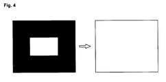
- the PDP can reduce consumed power by controlling the APL, since the APL-Nsus curve is nonlinear, an afterimage becomes severer. For instance, as shown in FIG. 4, the PDP driving circuit partially displays a bright part on the PDP and then displays the bright image on the whole screen with the same brightness. However, even though the bright image is displayed on the whole screen with the same brightness, the bright part which has been discharged becomes brighter and an afterimage remains. This is because the number of sustain pulses decreases abruptly when the partially bright image (that is, an image with a low APL) changes to the entirely bright image (that is, an image with a high APL).
- priming charge particles exist within a cell at a previously discharged part, and due to the priming charge particles, the previously discharged part appears to be brighter than a part which has been not discharged.
- the afterimage phenomenon is caused by an abrupt increase or decrease ⁇ Nsus in the number of sustain pulses according to the ALP by the APL-Nsus curve of an exponential function shape.
- an object of the present invention is to address at least the problems and disadvantages of the background art.
- An object of the present invention is to provide a method and an apparatus for decreasing an afterimage of a PDP by using a prescribed function period on an APL-Nsus curve.
- the invention provides a method for decreasing an afterimage of a plasma display panel by using an average picture level, comprising driving the plasma display panel by: calculating an average picture level of an input image; and deriving the number of sustain pulses corresponding to the calculated average picture level from a relationship between the average picture level-to-the number of sustain pulses.
- This relationship may be provided, for example, by generating an average picture level-to-sustain pulse number curve having a trigonometric function period or a linear function period.
- the invention provides an apparatus for decreasing an afterimage of a plasma display panel by using an average picture level, comprising an: average picture level (APL) calculating part for calculating an average picture level of an input image, and deriving the number of sustain pulses corresponding to the calculated average picture level from an average picture level-to-sustain pulse number relationship or curve having a trigonometric function period or a linear function period; and a driving part for a driving the plasma display panel by using the number of sustain pulses derived by the average picture level calculating part.
- APL average picture level
- the method and appratus for decreasing an afterimage of a PDP by using an APL according to the present invention can minimize the afterimage by using an APL-Nsus curve having a trigonometric function period or a linear function period and preventing an abrupt change in the number of sustain pulses when the APL varies.
- the invention also provides a visual display unit, such as a television, comprising a plasma display panel controlled using the above apparatus or method.
- a method for decreasing an afterimage of a plasma display panel by using an average picture level comprises the steps of: generating an average picture level-to-sustain pulse number curve having a trigonometric function period or a linear function period; and driving the plasma display panel by calculating an average picture level of an input image, and deriving the number of sustain pulses corresponding to the calculated average picture level from the average picture level-to-the number of sustain pulses curve.
- the trigonometric function period or the linear function period may exist between 5 and 95 percent of a peak average picture level on the average picture level-to-the sustain pulse number curve.
- an apparatus for decreasing an afterimage of a plasma display panel by using an average picture level comprises: an average picture level calculating part for calculating an average picture level of an input image, and deriving the number of sustain pulses corresponding to the calculated average picture level from an average picture level-to-sustain pulse number curve having a trigonometric function period or a linear function period; and a driving part for a driving the plasma display panel by using the number of sustain pulses derived by the average picture level calculating part.
- the trigonometric function period or the linear function period may exist between 5 and 95 percent of a peak average picture level on the average picture level-to-sustain pulse number curve.
- FIG. 5 is a block diagram illustrated to describe a method and apparatus for decreasing an afterimage of a PDP according to the present invention.
- a PDP driving circuit according to the present invention includes a gain correcting part 32, an error spreading part 33 and a subfield mapping part 34 connected between a first reverse gamma correcting part 31A and a data arranging part 35, and includes a trigonometric function/linear function APL calculating part 36 connected between a second reverse gamma correcting part 31 B and a waveform generating part 37.
- the first and second reverse gamma correcting parts 31A and 31 B perform reverse gamma correction on RGB digital video data from an input line 30 to convert luminance corresponding to a gray scale of a video signal into a linear value.
- the gain correcting part 32 compensates a color temperature by adjusting an effective gain according to respective data of RGB colors.
- the error spreading part 33 minutely adjusts a luminance value by spreading to adjacent cells a quantization error of the RGB input digital video data received from the gain correcting part 32.
- the subfield mapping part 34 maps data received from the error spreading part 33 to a subfield pattern stored previously according to each bit and supplies the mapped data to the data arranging part 35.
- the data arranging part 35 supplies a data driving circuit of a PDP 38 with digital video data received from the subfield mapping part 34.
- the data driving circuit connected to data electrodes of the PDP 38 latches data received from the data arranging part 35 on a horizontal line basis and supplies the latched data to the data electrodes of the PDP 38 in the unit of one horizontal period.
- the trigonometric function/linear function APL calculating part 36 calculates an APL of data received from the second reverse gamma correcting part 31 B, and derives the number of sustain pulses, Nsus, corresponding to the calculated APL from an APL-Nsus curve having a trigonometric function period.
- the NPL-Nsus curve having the trigonometric function period includes a sine (Sin) or cosine (Cos) function as shown in FIG. 6 or 7.
- the trigonometric function/linear function APL calculating part 36 calculates an APL of data received from the second reverse gamma correcting part 31 B, and derives the Nsus corresponding to the calculated APL from an APL-Nsus curve having a linear function period.
- the trigonometric function period or the linear function period exists between 5 and 95 percent of a peak APL, that is, a maximum average brightness on the APL-Nsus curve.
- the APL-Nsus curve is stored in a ROM (not shown) as lookup table data.
- the waveform generating part 37 generates a timing control signal in response to information about the Nsus from the trigonometric function/linear function APL calculating part 36 and supplies the timing control signal to a scan driving circuit and a sustain driving circuit which are not shown.
- the scan driving circuit and the sustain driving circuit supply sustain pulses to the scan electrodes and sustain electrodes of the PDP 38 during a sustain period in response to the timing control signal received from the waveform generating part 37.
- the method and apparatus for decreasing an afterimage of a PDL according to the present invention drives the PDP by using the APL-Nsus curve having the trigonometric function period or the linear function period. Therefore, the method and apparatus can prevent the number of sustain pulses from being abruptly changed when the APL varies. As a result, even though a bright part is partially displayed on the PDP and then it is displayed on the whole screen with the same brightness, an afterimage remains hardly because the number of sustain pulses does not change abruptly.
Landscapes
- Engineering & Computer Science (AREA)
- Physics & Mathematics (AREA)
- Power Engineering (AREA)
- Plasma & Fusion (AREA)
- Computer Hardware Design (AREA)
- General Physics & Mathematics (AREA)
- Theoretical Computer Science (AREA)
- Control Of Indicators Other Than Cathode Ray Tubes (AREA)
- Control Of Gas Discharge Display Tubes (AREA)
- Transforming Electric Information Into Light Information (AREA)
Abstract
Description
Claims (5)
- A method for decreasing an afterimage of a plasma display panel by using an average picture level, comprising the steps of:generating an average picture level-to-sustain pulse number curve having a trigonometric function period or a linear function period; anddriving the plasma display panel by calculating an average picture level of an input image, and deriving the number of sustain pulses corresponding to the calculated average picture level from the average picture level-to-the number of sustain pulses curve.
- The method as claimed in claim 1, wherein the trigonometric function period or the linear function period exists between 5 and 95 percent of a peak average picture level on the average picture level-to-the sustain pulse number curve.
- An apparatus for decreasing an afterimage of a plasma display panel by using an average picture level, comprising:an average picture level calculating part for calculating an average picture level of an input image, and deriving the number of sustain pulses corresponding to the calculated average picture level from an average picture level-to-sustain pulse number curve having a trigonometric function period or a linear function period; anda driving part for a driving the plasma display panel by using the number of sustain pulses derived by the average picture level calculating part.
- The apparatus as claimed in claim 3, wherein the trigonometric function period or the linear function period exists between 5 and 95 percent of a peak average picture level on the average picture level-to-sustain pulse number curve.
- A visual display unit comprising a plasma display panel controlled by means of the method or apparatus of any preceding claim.
Applications Claiming Priority (2)
| Application Number | Priority Date | Filing Date | Title |
|---|---|---|---|
| KR10-2003-0073312A KR100520833B1 (en) | 2003-10-21 | 2003-10-21 | Method and Apparatus For Decreasing Image Sticking Phenomenon |
| KR2003073312 | 2003-10-21 |
Publications (2)
| Publication Number | Publication Date |
|---|---|
| EP1526500A2 true EP1526500A2 (en) | 2005-04-27 |
| EP1526500A3 EP1526500A3 (en) | 2007-02-28 |
Family
ID=34386786
Family Applications (1)
| Application Number | Title | Priority Date | Filing Date |
|---|---|---|---|
| EP04256448A Ceased EP1526500A3 (en) | 2003-10-21 | 2004-10-20 | Method and apparatus for decreasing an afterimage of a plasma display panel |
Country Status (6)
| Country | Link |
|---|---|
| US (1) | US20050140587A1 (en) |
| EP (1) | EP1526500A3 (en) |
| JP (1) | JP2005128544A (en) |
| KR (1) | KR100520833B1 (en) |
| CN (1) | CN100365685C (en) |
| TW (1) | TWI294608B (en) |
Cited By (1)
| Publication number | Priority date | Publication date | Assignee | Title |
|---|---|---|---|---|
| WO2015113394A1 (en) * | 2014-01-29 | 2015-08-06 | 京东方科技集团股份有限公司 | Image sticking reduction method, device and display device |
Families Citing this family (7)
| Publication number | Priority date | Publication date | Assignee | Title |
|---|---|---|---|---|
| KR20040083188A (en) * | 2003-03-21 | 2004-10-01 | 엘지전자 주식회사 | Method and apparatus for calculating an average picture level being based on asymmetric cell |
| KR20080006824A (en) * | 2006-07-13 | 2008-01-17 | 엘지전자 주식회사 | Plasma display device |
| CN101727819B (en) * | 2008-10-24 | 2013-05-22 | 四川世纪双虹显示器件有限公司 | Method for enhancing image grey scale quality of AC plasma display |
| US8125569B2 (en) * | 2008-12-03 | 2012-02-28 | Sony Corporation | Dynamic contrast on displays using average picture level and histogram analysis |
| JPWO2011030548A1 (en) * | 2009-09-11 | 2013-02-04 | パナソニック株式会社 | Plasma display panel driving method and plasma display device |
| KR102123585B1 (en) * | 2014-08-07 | 2020-06-17 | 엘지디스플레이 주식회사 | Timing controller and display device |
| CN116635927A (en) * | 2021-12-21 | 2023-08-22 | 京东方科技集团股份有限公司 | Brightness determination method, device, display panel, electronic device and storage medium |
Family Cites Families (13)
| Publication number | Priority date | Publication date | Assignee | Title |
|---|---|---|---|---|
| US5943032A (en) * | 1993-11-17 | 1999-08-24 | Fujitsu Limited | Method and apparatus for controlling the gray scale of plasma display device |
| US5956014A (en) * | 1994-10-19 | 1999-09-21 | Fujitsu Limited | Brightness control and power control of display device |
| JP3142458B2 (en) * | 1995-05-08 | 2001-03-07 | 富士通株式会社 | Display device control method and display device |
| JP3544055B2 (en) * | 1996-03-07 | 2004-07-21 | 富士通株式会社 | Driving device for plasma display panel |
| JP2001125536A (en) * | 1999-10-29 | 2001-05-11 | Matsushita Electric Ind Co Ltd | Driving method of plasma display panel |
| KR20010077727A (en) * | 2000-02-08 | 2001-08-20 | 김순택 | Method and apparatus to control drive-power for plasma display panel |
| JP4642319B2 (en) * | 2000-07-28 | 2011-03-02 | トムソン ライセンシング | Method and apparatus for power level control of a display device |
| TWI244103B (en) * | 2000-10-16 | 2005-11-21 | Matsushita Electric Industrial Co Ltd | Plasma display panel apparatus and method of driving the plasma display panel apparatus |
| JP4754079B2 (en) * | 2001-02-28 | 2011-08-24 | パナソニック株式会社 | Plasma display panel driving method, driving circuit, and plasma display device |
| JP4707887B2 (en) * | 2001-07-11 | 2011-06-22 | パナソニック株式会社 | Display control device and display device |
| EP1329869A1 (en) * | 2002-01-16 | 2003-07-23 | Deutsche Thomson-Brandt Gmbh | Method and apparatus for processing video pictures |
| EP1437706A3 (en) * | 2003-01-10 | 2007-10-10 | Thomson Licensing | Method for optimizing brightness in a display device and apparatus for implementing the method |
| EP1437705A1 (en) * | 2003-01-10 | 2004-07-14 | Deutsche Thomson-Brandt Gmbh | Method for optimizing brightness in a display device and apparatus for implementing the method |
-
2003
- 2003-10-21 KR KR10-2003-0073312A patent/KR100520833B1/en not_active Expired - Fee Related
-
2004
- 2004-10-20 EP EP04256448A patent/EP1526500A3/en not_active Ceased
- 2004-10-20 TW TW093131823A patent/TWI294608B/en not_active IP Right Cessation
- 2004-10-20 US US10/968,178 patent/US20050140587A1/en not_active Abandoned
- 2004-10-21 CN CNB2004100882179A patent/CN100365685C/en not_active Expired - Fee Related
- 2004-10-21 JP JP2004306719A patent/JP2005128544A/en active Pending
Cited By (2)
| Publication number | Priority date | Publication date | Assignee | Title |
|---|---|---|---|---|
| WO2015113394A1 (en) * | 2014-01-29 | 2015-08-06 | 京东方科技集团股份有限公司 | Image sticking reduction method, device and display device |
| US9761161B2 (en) | 2014-01-29 | 2017-09-12 | Boe Technology Group Co., Ltd. | Method and device for reducing imaging sticking, and display device |
Also Published As
| Publication number | Publication date |
|---|---|
| US20050140587A1 (en) | 2005-06-30 |
| TWI294608B (en) | 2008-03-11 |
| KR100520833B1 (en) | 2005-10-12 |
| JP2005128544A (en) | 2005-05-19 |
| CN1609932A (en) | 2005-04-27 |
| TW200521923A (en) | 2005-07-01 |
| EP1526500A3 (en) | 2007-02-28 |
| KR20050038103A (en) | 2005-04-27 |
| CN100365685C (en) | 2008-01-30 |
Similar Documents
| Publication | Publication Date | Title |
|---|---|---|
| EP1531451A2 (en) | Method and apparatus for controlling initialization in plasma display panel | |
| CN100474372C (en) | Apparatus and method for driving plasma display panel | |
| JP2007193338A (en) | Plasma display device and driving method thereof | |
| US7515119B2 (en) | Method and apparatus for calculating an average picture level and plasma display using the same | |
| US7414598B2 (en) | Apparatus and method for driving plasma display panel | |
| US7256794B2 (en) | Method and apparatus for processing video data of display device | |
| JP2005092221A (en) | Device and method of driving plasma display panel | |
| EP1526500A2 (en) | Method and apparatus for decreasing an afterimage of a plasma display panel | |
| CN100501817C (en) | Apparatus and method of driving plasma display panel | |
| KR100480148B1 (en) | Method and apparatus of driving plasma display panel | |
| JP4160575B2 (en) | Plasma display device and driving method thereof | |
| KR100493915B1 (en) | Method and apparatus for driving plasma display panel | |
| JP2005128542A (en) | Method and device for driving plasma display panel | |
| KR100480167B1 (en) | Apparatus and method of driving plasma display panel | |
| US20070103398A1 (en) | Method and apparatus for power level control in a display device | |
| KR100482345B1 (en) | Method for driving plasma display panel using liquid crystal | |
| KR100692824B1 (en) | Driving device and driving method of plasma display panel | |
| US20050007311A1 (en) | Apparatus and method for driving a plasma display panel | |
| KR20050111007A (en) | Method and apparatus for driving plasma display panel | |
| KR20090044333A (en) | Plasma display device | |
| KR20030090812A (en) | Plasma display panel and driving method thereof | |
| KR20050012466A (en) | Apparatus and Method of Driving Plasma Display Panel |
Legal Events
| Date | Code | Title | Description |
|---|---|---|---|
| PUAI | Public reference made under article 153(3) epc to a published international application that has entered the european phase |
Free format text: ORIGINAL CODE: 0009012 |
|
| AK | Designated contracting states |
Kind code of ref document: A2 Designated state(s): AT BE BG CH CY CZ DE DK EE ES FI FR GB GR HU IE IT LI LU MC NL PL PT RO SE SI SK TR |
|
| AX | Request for extension of the european patent |
Extension state: AL HR LT LV MK |
|
| PUAL | Search report despatched |
Free format text: ORIGINAL CODE: 0009013 |
|
| AK | Designated contracting states |
Kind code of ref document: A3 Designated state(s): AT BE BG CH CY CZ DE DK EE ES FI FR GB GR HU IE IT LI LU MC NL PL PT RO SE SI SK TR |
|
| AX | Request for extension of the european patent |
Extension state: AL HR LT LV MK |
|
| RIC1 | Information provided on ipc code assigned before grant |
Ipc: G09G 3/288 20060101AFI20070125BHEP |
|
| 17P | Request for examination filed |
Effective date: 20070502 |
|
| 17Q | First examination report despatched |
Effective date: 20070731 |
|
| AKX | Designation fees paid |
Designated state(s): DE FR GB NL |
|
| STAA | Information on the status of an ep patent application or granted ep patent |
Free format text: STATUS: THE APPLICATION HAS BEEN REFUSED |
|
| 18R | Application refused |
Effective date: 20120401 |