EP1526301B1 - Compression spring with adjustable length and seat with such a spring - Google Patents
Compression spring with adjustable length and seat with such a spring Download PDFInfo
- Publication number
- EP1526301B1 EP1526301B1 EP04023129A EP04023129A EP1526301B1 EP 1526301 B1 EP1526301 B1 EP 1526301B1 EP 04023129 A EP04023129 A EP 04023129A EP 04023129 A EP04023129 A EP 04023129A EP 1526301 B1 EP1526301 B1 EP 1526301B1
- Authority
- EP
- European Patent Office
- Prior art keywords
- overflow
- valve
- casing
- compression spring
- throttle element
- Prior art date
- Legal status (The legal status is an assumption and is not a legal conclusion. Google has not performed a legal analysis and makes no representation as to the accuracy of the status listed.)
- Not-in-force
Links
- 230000006835 compression Effects 0.000 title claims description 30
- 238000007906 compression Methods 0.000 title claims description 30
- 238000007789 sealing Methods 0.000 claims description 3
- 239000012530 fluid Substances 0.000 claims 5
- 238000012986 modification Methods 0.000 claims 1
- 230000004048 modification Effects 0.000 claims 1
- 230000000284 resting effect Effects 0.000 claims 1
- 230000000903 blocking effect Effects 0.000 description 11
- 241001295925 Gegenes Species 0.000 description 5
- 238000006073 displacement reaction Methods 0.000 description 5
- 239000010720 hydraulic oil Substances 0.000 description 5
- 230000001960 triggered effect Effects 0.000 description 5
- 238000013016 damping Methods 0.000 description 2
- 238000003780 insertion Methods 0.000 description 2
- 230000037431 insertion Effects 0.000 description 2
- IHJMWZWIJOZWNP-XCNLKJTESA-N (3s,10s,13r,14r,17s)-17-[(2r)-6-amino-6-methylheptan-2-yl]-4,4,10,13,14-pentamethyl-2,3,5,6,7,11,12,15,16,17-decahydro-1h-cyclopenta[a]phenanthren-3-ol Chemical class C([C@@]12C)C[C@H](O)C(C)(C)C1CCC1=C2CC[C@]2(C)[C@H]([C@@H](CCCC(C)(C)N)C)CC[C@]21C IHJMWZWIJOZWNP-XCNLKJTESA-N 0.000 description 1
- 230000000295 complement effect Effects 0.000 description 1
- 230000000694 effects Effects 0.000 description 1
- 238000004146 energy storage Methods 0.000 description 1
- 238000009434 installation Methods 0.000 description 1
- 239000007788 liquid Substances 0.000 description 1
- 230000013011 mating Effects 0.000 description 1
- 238000000034 method Methods 0.000 description 1
- 239000003566 sealing material Substances 0.000 description 1
- 230000035939 shock Effects 0.000 description 1
Images


Classifications
-
- B—PERFORMING OPERATIONS; TRANSPORTING
- B60—VEHICLES IN GENERAL
- B60N—SEATS SPECIALLY ADAPTED FOR VEHICLES; VEHICLE PASSENGER ACCOMMODATION NOT OTHERWISE PROVIDED FOR
- B60N2/00—Seats specially adapted for vehicles; Arrangement or mounting of seats in vehicles
- B60N2/02—Seats specially adapted for vehicles; Arrangement or mounting of seats in vehicles the seat or part thereof being movable, e.g. adjustable
- B60N2/04—Seats specially adapted for vehicles; Arrangement or mounting of seats in vehicles the seat or part thereof being movable, e.g. adjustable the whole seat being movable
- B60N2/10—Seats specially adapted for vehicles; Arrangement or mounting of seats in vehicles the seat or part thereof being movable, e.g. adjustable the whole seat being movable tiltable
-
- B—PERFORMING OPERATIONS; TRANSPORTING
- B60—VEHICLES IN GENERAL
- B60N—SEATS SPECIALLY ADAPTED FOR VEHICLES; VEHICLE PASSENGER ACCOMMODATION NOT OTHERWISE PROVIDED FOR
- B60N2/00—Seats specially adapted for vehicles; Arrangement or mounting of seats in vehicles
- B60N2/02—Seats specially adapted for vehicles; Arrangement or mounting of seats in vehicles the seat or part thereof being movable, e.g. adjustable
- B60N2/22—Seats specially adapted for vehicles; Arrangement or mounting of seats in vehicles the seat or part thereof being movable, e.g. adjustable the back-rest being adjustable
- B60N2/23—Seats specially adapted for vehicles; Arrangement or mounting of seats in vehicles the seat or part thereof being movable, e.g. adjustable the back-rest being adjustable by linear actuators, e.g. linear screw mechanisms
- B60N2/231—Seats specially adapted for vehicles; Arrangement or mounting of seats in vehicles the seat or part thereof being movable, e.g. adjustable the back-rest being adjustable by linear actuators, e.g. linear screw mechanisms by hydraulic actuators
-
- F—MECHANICAL ENGINEERING; LIGHTING; HEATING; WEAPONS; BLASTING
- F16—ENGINEERING ELEMENTS AND UNITS; GENERAL MEASURES FOR PRODUCING AND MAINTAINING EFFECTIVE FUNCTIONING OF MACHINES OR INSTALLATIONS; THERMAL INSULATION IN GENERAL
- F16F—SPRINGS; SHOCK-ABSORBERS; MEANS FOR DAMPING VIBRATION
- F16F9/00—Springs, vibration-dampers, shock-absorbers, or similarly-constructed movement-dampers using a fluid or the equivalent as damping medium
- F16F9/02—Springs, vibration-dampers, shock-absorbers, or similarly-constructed movement-dampers using a fluid or the equivalent as damping medium using gas only or vacuum
- F16F9/0209—Telescopic
- F16F9/0245—Means for adjusting the length of, or for locking, the spring or dampers
- F16F9/0272—Means for adjusting the length of, or for locking, the spring or dampers with control rod extending through the piston rod into the piston
Definitions
- the invention relates to a length-adjustable compression spring according to the preamble of claim 1. Furthermore, the invention relates to a seat with such a compression spring.
- Such a blockable compression spring is known from EP 1 288 525 A2.
- There two valves are arranged in series in the actuation Sprintströmitati between the two part-housing chambers in series.
- One of the two is the actuatable valve with the valve pin in the sense of the preamble of claim 1.
- the second valve is a load switching valve, which blocks the entire actuation overflow independently of the switching position of the actuatable valve.
- pressurizing the load switching valve can be transferred with open actuable valve in a release position in which the pressure medium can flow freely between the two part-housing chambers.
- This known compression spring is used in the backrest adjustment of vehicle seats.
- the user wants to bring this in a more upright position with the backrest inclined backwards, he first actuates the actuatable valve. As long as the back of the user does not exert any pressure on the backrest, the load switching valve remains in the blocking position, so that even with triggered actuatable valve, the backrest remains in the originally inclined position. Only when the user leans back so far that he generates a control pressure on the backrest, which transfers the load switching valve in the release position, both the actuatable valve and the load switching valve is open, the actuation overflow connection thus free. Only then does the backrest follow the user's back to a more upright position when the user is seated straighten yourself up.
- an adjustable gas spring which has a valve provided for actuating the piston rod valve with a damping valve, wherein the damping valve throttles differently when retracting the piston rod into the housing and the extension of the piston rod from the housing.
- EP 1 124 077 A1 discloses a gas spring with a valve device, which has at least two overflow channels with different throttling action, and these come into effect with differently wide insertion of a valve pin together or successively.
- the invention has the object of developing a compression spring of the type mentioned in such a way that a simultaneously comfortable and intuitive length adjustment of the compression spring is possible.
- the core of the invention is the provision of at least two parallel overflow channels in the actuation overflow connection.
- the second overflow channel is a bypass.
- a throttle element according to claim 2 is inexpensive to produce and can be made of low-wear, yet good sealing material.
- An actuation of the throttle element according to claim 3 is simple and does not require mechanical articulation of the throttle element.
- An embodiment of the throttle element according to claim 4 can be elegantly integrated into a compression spring and is particularly easy to use.
- An energy storage device according to claim 5 and a pressure medium according to claim 6 have - depending on the application - proven.
- Another object of the invention is to provide a seat in which the advantages of the compression spring according to the invention come into play particularly.
- An actuator according to claim 8 leads to a comfortable triggering of the valve pin.
- the user actuates the throttle element by pressure against the Lehn-1 the backrest of the seat.
- the throttle element When triggered valve pin thereby throttling the compression spring is released and a quick adjustment of the backrest tilt is possible.
- the compression spring according to the invention is used, for example, in office chairs. Alternatively, it may be used, for example, in vehicle seats such as bus seats, train seats or aircraft seats. Another application example is a cinema seat.
- the overall length-adjustable, blockable pressure gas spring shown in FIG. 1 has a substantially cylindrical housing 1 made of a tube, which is gas-tightly closed at one end 2 by means of a bottom 3, to which a fastening element 4 is attached.
- a ring-shaped guide and seal unit 6 is liquid-tightly secured, which serves to guide and seal a concentric with the central longitudinal axis 7 in the housing 1 piston rod 8 arranged.
- a fastener 10 is provided at the outside of the housing 1 located free end 9 of the piston rod 8 arranged.
- a piston 12 On located in the housing 1 end 11 of the piston rod 8, a piston 12 is mounted, which is guided on an inner wall 13 of the housing 1 and against this sealed by a seal 14 liquid-tight.
- the piston 12 divides the interior of the housing 1 into a located between the piston 12 and guide and seal unit 6 first part housing space 15 and a second part housing space facing away from the second part housing space 16 is in turn by a sliding piston 17th limited, which guided on the inner wall 13 of the housing 1 slidably and against this by means of a gasket 18 gas and is sealed liquid-tight.
- Between the sliding piston 17 and the bottom 3 in turn serving as a force storage pressure gas chamber 19 is arranged, in which gas is under pressure.
- the partial housing chambers 15, 16 are filled with a liquid as a pressure medium, for example hydraulic oil.
- a blocking valve 20 is formed as an actuatable valve, with which the part-housing chambers 15, 16 connected to each other or can be separated from each other. In interconnected part-housing chambers 15, 16 is between these an actuation overflow connection 21 before (see, for example, Fig. 5).
- the blocking valve 20 is shown in the closed position.
- the blocking valve 20 comprises a valve body 22, which is located on the sealing and guiding unit 6 facing side of the piston 12.
- hollow valve body 22 is a hollow cylindrical Matterström emotions 23 with a second part of the housing space 16 facing annular bottom 24 is formed.
- the overflow body 23 delimits a first overflow channel 25, which continues the actuation overflow connection 21 toward the first partial housing space 15.
- the overflow 23 on channel 23 which connect the interior of the overflow 23 with an annular space 27 in the valve body 22.
- the annular space 27 is in turn connected via a further branch channel 28 in the valve body 22 with the first part housing space 15 in connection.
- a bypass groove 29 is executed, which represents a second overflow, which is also connected as part of the overflow 21 parallel to the first overflow 25, that is a bypass for this.
- bypass groove 29 like the first overflow channel 25, with the actuation overflow connection 21 open, connects the second part housing space 16 via the annular space 27 and the branch passage 28 in the valve body 22 to the first part housing space 15.
- the overflow 23 is arranged by a coaxial with the axis 7 arranged and displaceable valve pin 30, which is shown in Fig. 1 in the closed position.
- the valve pin 30 is sealed between the overflow body 23 and the hollow piston rod 8 by means of a seal 31 to the outside.
- the valve pin 30 has at its end pointing to the second part housing space 16 on a two-stage conically widening valve disk 32.
- An arranged at the free end of the valve pin 30 cone wall 33 of the valve plate 32 with a larger diameter serves as a movement limit of the valve pin 30 in the extension direction of this.
- the cone wall 33 works for this purpose with a mating surface 34 of the valve body 22 together.
- a seal 34 a having a rectangular cross-section seals the cone wall 33 against the valve body 22. Between the two conical surfaces, the valve pin 30 has a cylindrical wall 35. This seals against the overflow 23 via a throttle element 36 performing seal in the throttle position shown in Fig. 1 from.
- the throttle element 36 is formed as an O-ring.
- the throttle element 36 In the throttle position, the throttle element 36 is in the direction of the second part of the housing space 16 to the ring bottom 24 of the overflow 23. In this way, the throttle element 36 is secured against further displacement along the central longitudinal axis 7 in the direction of the second partial housing space 16. In the opposite direction, ie in the arrow direction of the arrow 37, a displacement movement of the throttle element 36 is within a formed by the overflow 23 and an adjacent intermediate ring 38 in the valve body 22 overflow 39, which is part of the first transfer port 25, possible, as is shown in detail.
- the valve pin 30 has in the region between the voltage applied to the seal 31 portion and the valve plate 32 a tapered portion 40, between which and the adjacent parts, namely the overflow 23 and the intermediate ring 38, a communicating with the branch channels 26 annular space 41 is formed ,
- valve actuating rod 42 In the hollow piston rod 8 is a displaceable in the direction of the axis 7, from the end 9 ago by moving operable valve actuating rod 42 is arranged, which rests against the valve pin 30.
- the free, protruding from the piston rod 8 end of the valve actuating rod 42 is formed as an actuating knob 43.
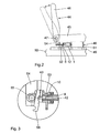
- Fig. 2 shows schematically the arrangement of the pressure-gas spring according to FIG. 1 on a likewise schematically illustrated seat 44.
- This has a seat surface 45 and a backrest 46.
- the backrest 46 is pivotable about the seat surface 45 about a pivot joint 47.
- the seat 44 is a vehicle seat that may be used in, for example, a bus, a train or an airplane.
- a support frame 48 which connects the seat surface 45 with a support rail 49 which is fixed to the bottom 50.
- the support frame 48 is connected in a known manner with the support rail 49, that the seat 44 can be adjusted to change the distance between successively arranged seats 44.
- the supporting frame 48 has three in the adjustment direction successively arranged, vertical support struts 51. Between the middle strut 51 and the swivel joint 47 adjacent arranged, rear support strut 51, the pressure gas spring of FIG. 1 is arranged horizontally.
- the fastening element 4 is rotatably mounted on the central support strut 51.
- the piston rod 8 is guided axially on a guide opening 52 in the rear support strut 51.
- the free end 9 of the piston rod 8 is connected via the fastening element 10 and a connecting body 53 with a connecting rod 54, wherein between the connecting body 53 and the connecting rod 54, a pivot joint 55 is arranged with the pivot joint 47 parallel pivot axis.
- the connecting rod 54 is an extension of the backrest 46 on the pivot joint 47 also out and is firmly connected to the backrest 46 also pivotable about the pivot joint 47.
- Fig. 2 shows the backrest 46 is pulled through in an upright position in which the piston rod 8 of the pressure gas spring is pushed out of the housing 1 maximum.
- Dashed lines Fig. 2 shows the backrest 46 in a relation to the upright position more inclined position in which the backrest 46 and thus the connecting rod 54 are pivoted about the pivot joint 47 and in which the piston rod 8 and connected to this piston 12 in the Housing 1 of the pressure gas spring are inserted.
- a complementary shaped abutment portion of an actuating body 56 is provided which is pivotally mounted on the connecting body 53 and, for example via a corresponding Bowden cable, with a arranged in the bottom of the seat 45 control lever or push button for actuating the valve actuating rod 42 cooperates.
Landscapes
- Engineering & Computer Science (AREA)
- Mechanical Engineering (AREA)
- General Engineering & Computer Science (AREA)
- Aviation & Aerospace Engineering (AREA)
- Transportation (AREA)
- Chairs For Special Purposes, Such As Reclining Chairs (AREA)
- Fluid-Damping Devices (AREA)
- Springs (AREA)
Abstract
Description
Die Erfindung betrifft eine längenverstellbare Druckfeder nach dem Oberbegriff des Anspruchs 1. Ferner betrifft die Erfindung einen Sitz mit einer derartigen Druckfeder.The invention relates to a length-adjustable compression spring according to the preamble of
Eine derartige blockierbare Druckfeder ist bekannt aus der EP 1 288 525 A2. Dort sind in der Betätigungs-Überströmverbindung zwischen den beiden Teil-Gehäuseräumen in Reihe zwei Ventile angeordnet. Eines der beiden ist das betätigbare Ventil mit dem Ventilstift im Sinne des Oberbegriffs des Anspruchs 1. Das zweite Ventil ist ein Lastschaltventil, welches unabhängig von der Schaltstellung des betätigbaren Ventils die gesamte Betätigungs-Überströmverbindung blockiert. Durch Druckbeaufschlagung lässt sich das Lastschaltventil bei geöffnetem betätigbarem Ventil in eine Freigabestellung überführen, in welcher das Druck-Medium frei zwischen den beiden Teil-Gehäuseräumen fließen kann. Diese bekannte Druckfeder findet Anwendung bei der Rückenlehnenverstellung von Fahrzeugsitzen. Will der Benutzer bei nach hinten geneigter Rückenlehne diese in eine aufrechtere Position bringen, so betätigt er zunächst das betätigbare Ventil. Solange der Rücken des Benutzers keinen Druck auf die Rückenlehne ausübt, verbleibt das Lastschaltventil in der Blockierstellung, sodass auch bei ausgelöstem betätigbaren Ventil die Rückenlehne in der ursprünglich geneigten Position verbleibt. Erst wenn der Benutzer sich soweit zurücklehnt, dass er über die Rückenlehne einen Steuerdruck erzeugt, welcher das Lastschaltventil in die Freigabestellung überführt, ist sowohl das betätigbare Ventil als auch das Lastschaltventil offen, die Betätigungs-Überströmverbindung also frei. Erst dann folgt die Rückenlehne dem Rücken des Benutzers in eine aufrechtere Position, wenn der Benutzer sich selber aufrichtet. Dieses Konzept zur Umstellung der Rückenlehne in die aufrechtere Position vermeidet zwar, dass die Druckfeder nach einer Betätigung des betätigbaren Ventils unkontrolliert ausschiebt und gegen den Rücken des Benutzers stößt, ist aber kompliziert und vor allem wenig intuitiv. Nach einer Betätigung des betätigbaren Ventils muss der Benutzer sich erst stärker zurücklehnen, obwohl er doch in eine aufrechtere Position gelangen will.Such a blockable compression spring is known from
Aus der US 4,844,392 ist eine längenverstellbare Gasfeder bekannt, die ein zur Betätigung der Kolbenstange vorgesehenes Ventil mit einem Dämpfungs-Ventil aufweist, wobei das Dämpfungs-Ventil beim Einfahren der Kolbenstange in das Gehäuse und beim Ausfahren der Kolbenstange aus dem Gehäuse jeweils unterschiedlich drosselt.From US 4,844,392 an adjustable gas spring is known, which has a valve provided for actuating the piston rod valve with a damping valve, wherein the damping valve throttles differently when retracting the piston rod into the housing and the extension of the piston rod from the housing.
Die EP 1 124 077 A1 offenbart eine Gasfeder mit einer Ventil-Einrichtung, die mindestens zwei Überströmkanäle mit unterschiedlicher Drosselwirkung aufweist, wobei diese bei unterschiedlich weitem Einschieben eines Ventilstiftes gemeinsam oder nacheinander zur Wirkung kommen.
Aus der JP 5 248 469 A ist eine Kolben-Zylinder-Einheit zur Betätigung von Rückenlehnen bekannt, die in Ausschub- und in Einschubrichtung eine unterschiedliche Drossenwirkung aufweist.From JP 5 248 469 A a piston-cylinder unit for operating backrests is known which has a different Drossenwirkung in Ausschub- and in the direction of insertion.
Der Erfindung liegt die Aufgabe zugrunde, eine Druckfeder der eingangs genannten Art derart weiterzubilden, dass eine gleichzeitig komfortable und intuitive Längenverstellung der Druckfeder möglich ist.The invention has the object of developing a compression spring of the type mentioned in such a way that a simultaneously comfortable and intuitive length adjustment of the compression spring is possible.
Diese Aufgabe ist erfindungsgemäß gelöst durch die im Kennzeichnungsteil des Anspruchs 1 angegebenen Merkmale.This object is achieved by the features specified in the characterizing part of
Kern der Erfindung ist das Vorsehen von mindestens zwei parallel geschalteten Überströmkanälen in der Betätigungs-Überströmverbindung. Für einen ersten Überströmkanal, in dem das Drosselelement vorgesehen ist, stellt somit der zweite Überströmkanal einen Bypass dar. Somit ist auch dann, wenn das Drosselelement in Drosselstellung vorliegt, bei ausgelöstem betätigbaren Ventil ein Überströmen von Druckmedium zwischen den Teil-Gehäuseräumen möglich. Bei von außen herbeiführbarer Überführung des Drosselelements in die Freigabestellung sind beide Überströmkanäle offen, sodass die Drosselung der Betätigungs-Überströmverbindung aufgehoben ist. Eine Betätigung des betätigbaren Ventils führt also auch dann, wenn das Drosselelement in Drosselstellung vorliegt, zu einer - wenn auch gedrosselten - Aufhebung der Blockierung der Druckfeder. Aufgrund der Drosselung ist ein unkontrolliertes Ausschieben der Kolbenstange verhindert. Es resultiert eine komfortable und gleichzeitig intuitive Längenverstellung der Druckfeder, wobei sich die Druckfeder mit einer geringen Anzahl von Komponenten realisieren lässt.The core of the invention is the provision of at least two parallel overflow channels in the actuation overflow connection. Thus, for a first overflow channel, in which the throttle element is provided, the second overflow channel is a bypass. Thus, even when the throttle element is in throttle position, with triggered operable valve overflow of pressure medium between the part-housing spaces possible. In externally brought about transfer of the throttle element in the release position, both transfer ports are open, so that the throttling of the actuation overflow connection is canceled. An actuation of the actuatable valve thus leads, even if the throttle element is in throttle position, to a - albeit throttled - lifting the blocking of the compression spring. Due to the throttling an uncontrolled pushing out of the piston rod is prevented. The result is a comfortable and at the same time intuitive length adjustment of the compression spring, whereby the compression spring can be realized with a small number of components.
Ein Drosselelement nach Anspruch 2 ist kostengünstig herstellbar und kann aus verschleißarmem und trotzdem gut dichtendem Material gefertigt sein.A throttle element according to
Eine Betätigung des Drosselelements gemäß Anspruch 3 ist einfach und erfordert keine mechanische Anlenkung des Drosselelements.An actuation of the throttle element according to
Eine Ausgestaltung des Drosselelements nach Anspruch 4 kann elegant in eine Druckfeder integriert werden und ist besonders bedienungsfreundlich.An embodiment of the throttle element according to
Ein Kraftspeicher nach Anspruch 5 sowie ein Druck-Medium nach Anspruch 6 haben sich - je nach Einsatzgebiet - bewährt.An energy storage device according to
Eine weitere Aufgabe der Erfindung ist es, einen Sitz anzugeben, bei dem die Vorteile der erfindungsgemäßen Druckfeder besonders zum Tragen kommen.Another object of the invention is to provide a seat in which the advantages of the compression spring according to the invention come into play particularly.
Diese Aufgabe ist erfindungsgemäß gelöst durch einen Sitz gemäß Anspruch 7.This object is achieved by a seat according to
Beim erfindungsgemäßen Sitz wird vermieden, dass die Rückenlehne nach einem Auslösen des Ventilstifts durch Ausschieben der Kolbenstange unkontrolliert in eine aufgerichtete Position schnellt und dabei dem Sitzenden einen Stoß versetzt. Stattdessen erfolgt ein gedrosseltes und daher langsames Aufrichten der Rückenlehne. Wenn das Drosselelement zusätzlich in die Freigabestellung überführt wird, wird die Drosselung kontrolliert aufgehoben und eine schnellere Rückenlehnenverstellung ist möglich.When seat according to the invention it is avoided that the backrest after triggering of the valve pin by pushing out the piston rod jumps uncontrollably in an upright position and thereby puts a shock to the seated. Instead, there is a throttled and therefore slow uprighting of the backrest. If the throttle element is additionally transferred to the release position, the throttling is canceled controlled and a faster backrest adjustment is possible.
Ein Betätigungselement nach Anspruch 8 führt zu einem bequemen Auslösen des Ventilstifts.An actuator according to
Bei einer Anordnung der Druckfeder nach Anspruch 9 betätigt der Benutzer durch Druck gegen die Lehnfläche der Rückenlehne des Sitzes das Drosselelement. Bei ausgelöstem Ventilstift wird dadurch die Drosselung der Druckfeder aufgehoben und eine schnelle Verstellung der Rückenlehnenneigung ist möglich.In an arrangement of the compression spring according to
Die erfindungsgemäße Druckfeder kommt zum Beispiel bei Bürostühlen zum Einsatz. Alternativ kann sie zum Beispiel bei Fahrzeugsitzen wie Bussitzen, Zugsitzen oder Flugzeugsitzen zur Anwendung kommen. Ein anderes Anwendungsbeispiel ist ein Kinositz.The compression spring according to the invention is used, for example, in office chairs. Alternatively, it may be used, for example, in vehicle seats such as bus seats, train seats or aircraft seats. Another application example is a cinema seat.
Weitere Merkmale, Vorteile und Einzelheiten der Erfindung ergeben sich aus der nachfolgenden Beschreibung eines Ausführungsbeispiels anhand der Zeichnung. In dieser zeigen:
- Fig. 1
- eine Druckfeder im Längsschnitt;
- Fig. 2
- eine schematische Darstellung eines Sitzes mit einer erfindungsgemäßen Druckfeder;
- Fig. 3
- eine Ausschnittsvergrößerung aus Fig. 2, welche in Fig. 2 nicht sichtbare Details einer Ventilbetätigung der Druckfeder darstellt; und
- Fig. 4 bis 7
- Momentaufnahmen eines Ausschnitts der Druckfeder im Bereich eines Kolbens von dieser, welche die Verlagerung eines Ventilstifts sowie eines Drosselelements bei der Betätigung des Ventils der Druckfeder darstellen.
- Fig. 1
- a compression spring in longitudinal section;
- Fig. 2
- a schematic representation of a seat with a compression spring according to the invention;
- Fig. 3
- an enlarged detail of Figure 2, which is not visible in Figure 2 Details of a valve actuation of the compression spring ..; and
- Fig. 4 to 7
- Snapshots of a section of the compression spring in the region of a piston of this, which represent the displacement of a valve pin and a throttle element in the operation of the valve of the compression spring.
Die in Fig. 1 insgesamt dargestellte längenverstellbare, blockierbare Druck-Gasfeder weist ein im Wesentlichen zylindrisches, aus einem Rohr hergestelltes Gehäuse 1 auf, das an einem Ende 2 mittels eines Bodens 3 gasdicht verschlossen ist, an dem ein Befestigungselement 4 angebracht ist. Am anderen Ende 5 des Gehäuses 1 ist eine ringförmig ausgebildete Führungs- und Dichtungs-Einheit 6 flüssigkeitsdicht befestigt, die zur Führung und Abdichtung einer im Gehäuse 1 konzentrisch zu dessen Mittel-Längs-Achse 7 verschiebbar angeordneten Kolbenstange 8 dient. Am außerhalb des Gehäuses 1 befindlichen freien Ende 9 der Kolbenstange 8 ist ebenfalls ein Befestigungselement 10 vorgesehen.The overall length-adjustable, blockable pressure gas spring shown in FIG. 1 has a substantially
Am im Gehäuse 1 befindlichen Ende 11 der Kolbenstange 8 ist ein Kolben 12 angebracht, der an einer Innenwand 13 des Gehäuses 1 geführt ist und gegenüber dieser mittels einer Dichtung 14 flüssigkeitsdicht abgedichtet ist. Der Kolben 12 teilt den Innenraum des Gehäuses 1 in einen zwischen Kolben 12 und Führungs- und Dichtungs-Einheit 6 befindlichen ersten Teil-Gehäuseraum 15 und einen hiervon abgewandten zweiten Teil-Gehäuseraum 16. Der zweite Teil-Gehäuseraum 16 wiederum wird durch einen Schiebekolben 17 begrenzt, der an der Innenwand 13 des Gehäuses 1 geführt verschiebbar und gegenüber dieser mittels einer Dichtung 18 gas- und flüssigkeitsdicht abgedichtet ist. Zwischen dem Schiebekolben 17 und dem Boden 3 wiederum ist eine als Kraftspeicher dienende Druckgas-Kammer 19 angeordnet, in der sich Gas unter Druck befindet. Die Teil-Gehäuseräume 15, 16 sind mit einer Flüssigkeit als Druck-Medium, beispielsweise Hydrauliköl, gefüllt.On located in the
Im Kolben 12 ist ein Blockier-Ventil 20 als betätigbares Ventil ausgebildet, mit dem die Teil-Gehäuseräume 15, 16 miteinander verbunden beziehungsweise voneinander getrennt werden können. Bei miteinander verbundenen Teil-Gehäuseräumen 15, 16 liegt zwischen diesen eine Betätigungs-Überströmverbindung 21 vor (vergleiche zum Beispiel Fig. 5). In Fig. 1 ist das Blockier-Ventil 20 in Schließstellung dargestellt. Das Blockier-Ventil 20 umfasst einen Ventilkörper 22, der sich auf der der Dichtungs- und Führungs-Einheit 6 zugewandten Seite des Kolbens 12 befindet. Im hohl ausgebildeten Ventilkörper 22 ist ein hohlzylindrischer Überströmkörper 23 mit einem dem zweiten Teil-Gehäuseraum 16 zugewandten Ringboden 24 ausgebildet. Nach innen, also zur Mittel-Längs-Achse 7 hin, begrenzt der Überströmkörper 23 einen ersten Überströmkanal 25, der die Betätigungs-Überströmverbindung 21 hin zum ersten Teil-Gehäuseraum 15 fortsetzt. Hierzu weist der Überströmkörper 23 Stichkanäle 26 auf, die den Innenraum des Überströmkörpers 23 mit einem Ringraum 27 im Ventilkörper 22 verbinden. Der Ringraum 27 steht seinerseits über einen weiteren Stichkanal 28 im Ventilkörper 22 mit dem ersten Teil-Gehäuseraum 15 in Verbindung.In the
In der Außenwand des Ringbodens 24 sowie des weiteren Überströmkörpers 23 ist eine Bypassnut 29 ausgeführt, welche einen zweiten Überströmkanal darstellt, der ebenfalls als Teil der Überströmverbindung 21 parallel zum ersten Überströmkanal 25 geschaltet, also ein Bypass für diesen ist.In the outer wall of the
Auch die Bypassnut 29 verbindet wie der erste Überströmkanal 25 bei geöffneter Betätigungs-Überströmverbindung 21 den zweiten Teil-Gehäuseraum 16 über den Ringraum 27 und den Stichkanal 28 im Ventilkörper 22 mit dem ersten Teil-Gehäuseraum 15.The
Der Überströmkörper 23 wird von einem koaxial zur Achse 7 angeordneten und verschiebbaren Ventilstift 30 durchsetzt, der in Fig. 1 in Schließstellung dargestellt ist. Der Ventilstift 30 ist zwischen dem Überströmkörper 23 und der hohl ausgebildeten Kolbenstange 8 mittels einer Dichtung 31 nach außen abgedichtet. Der Ventilstift 30 weist an seinem zum zweiten Teil-Gehäuseraum 16 weisenden Ende einen sich zweistufig konusförmig erweiternden Ventilteller 32 auf. Eine am freien Ende des Ventilstifts 30 angeordnete Konuswand 33 des Ventiltellers 32 mit größerem Durchmesser dient als Bewegungsbegrenzung des Ventilstifts 30 in Ausschubrichtung von diesem. Die Konuswand 33 arbeitet hierzu mit einer Gegenfläche 34 des Ventilkörpers 22 zusammen. In der in Fig. 1 gezeigten Schließstellung des Ventils 20 dichtet eine einen rechteckigen Querschnitt aufweisende Dichtung 34a die Konuswand 33 gegen den Ventilkörper 22 ab. Zwischen den beiden Konusflächen weist der Ventilstift 30 eine zylindrische Wand 35 auf. Diese dichtet gegen den Überströmkörper 23 über eine ein Drosselelement 36 darstellende Dichtung in der in Fig. 1 dargestellten Drosselstellung ab. Das Drosselelement 36 ist als O-Ring ausgebildet.The
In der Drosselstellung liegt das Drosselelement 36 in Richtung auf den zweiten Teil-Gehäuseraum 16 zu am Ringboden 24 des Überströmkörpers 23 an. Auf diese Weise ist das Drosselelement 36 gegen eine weitere Verlagerung längs der Mittel-Längs-Achse 7 in Richtung auf den zweiten Teil-Gehäuseraum 16 zu gesichert. In Gegenrichtung, also in Pfeilrichtung des Pfeils 37, ist eine Verlagerungsbewegung des Drosselelements 36 innerhalb eines durch den Überströmkörper 23 und einen hieran angrenzenden Zwischenring 38 im Ventilkörper 22 gebildeten Überströmraum 39, der Teil des ersten Überströmkanals 25 ist, möglich, wie noch im Einzelnen dargestellt ist.In the throttle position, the
Der Ventilstift 30 weist im Bereich zwischen dem an der Dichtung 31 anliegenden Abschnitt und dem Ventilteller 32 einen verjüngten Abschnitt 40 auf, zwischen dem und den benachbarten Teilen, nämlich dem Überströmkörper 23 und dem Zwischenring 38, ein mit den Stichkanälen 26 kommunizierender Ringraum 41 gebildet ist.The
In der hohl ausgebildeten Kolbenstange 8 ist eine in Richtung der Achse 7 verschiebbare, vom Ende 9 her durch Verschieben betätigbare Ventil-Betätigungs-Stange 42 angeordnet, die gegen den Ventilstift 30 anliegt. Das freie, aus der Kolbenstange 8 herausragende Ende der Ventil-Betätigungs-Stange 42 ist als Betätigungsknopf 43 ausgebildet.In the
Fig. 2 zeigt schematisch die Anordnung der Druck-Gasfeder gemäß Fig. 1 an einem ebenfalls schematisch dargestellten Sitz 44. Dieser weist eine Sitzfläche 45 und eine Rückenlehne 46 auf. Die Rückenlehne 46 ist gegen die Sitzfläche 45 um ein Schwenkgelenk 47 verschwenkbar. Beim Sitz 44 handelt es sich um einen Fahrzeug-Sitz, der zum Beispiel in einem Bus, in einem Zug oder in einem Flugzeug zum Einsatz kommen kann.Fig. 2 shows schematically the arrangement of the pressure-gas spring according to FIG. 1 on a likewise schematically illustrated
Unterhalb der Sitzfläche 45 ist ein Tragrahmen 48 angeordnet, der die Sitzfläche 45 mit einer Tragschiene 49, die am Boden 50 festgelegt ist, verbindet. Der Tragrahmen 48 ist dabei in bekannter Weise so mit der Tragschiene 49 verbunden, dass der Sitz 44 zur Veränderung des Abstands zwischen hintereinander angeordneten Sitzen 44 verstellt werden kann. Der Tragrahmen 48 weist drei in Verstellrichtung hintereinander angeordnete, senkrechte Stützstreben 51 auf. Zwischen der mittleren Strebe 51 und der dem Schwenkgelenk 47 benachbart angeordneten, hinteren Stützstrebe 51 ist die Druck-Gasfeder gemäß Fig. 1 horizontal angeordnet. Hierbei ist das Befestigungselement 4 an der mittleren Stützstrebe 51 drehbar gelagert. Die Kolbenstange 8 ist an einer Führungsöffnung 52 in der hinteren Stützstrebe 51 axial geführt. Das freie Ende 9 der Kolbenstange 8 ist über das Befestigungselement 10 und einen Verbindungskörper 53 mit einer Verbindungsstange 54 verbunden, wobei zwischen dem Verbindungskörper 53 und der Verbindungsstange 54 ein Schwenkgelenk 55 mit zum Schwenkgelenk 47 paralleler Schwenkachse angeordnet ist. Die Verbindungsstange 54 stellt eine Verlängerung der Rückenlehne 46 über das Schwenkgelenk 47 hinaus dar und ist fest verbunden mit der Rückenlehne 46 ebenfalls um das Schwenkgelenk 47 schwenkbar.Below the
Fig. 2 zeigt die Rückenlehne 46 durchgezogen in einer aufrechten Position, in der die Kolbenstange 8 der Druck-Gasfeder maximal aus dem Gehäuse 1 ausgeschoben ist. Gestrichelt zeigt Fig. 2 die Rückenlehne 46 in einer gegenüber der aufrechten Position stärker geneigten Position, in der die Rückenlehne 46 und damit auch die Verbindungsstange 54 um das Schwenkgelenk 47 verschwenkt sind und in der die Kolbenstange 8 und der mit dieser verbundene Kolben 12 in das Gehäuse 1 der Druck-Gasfeder eingeschoben sind.Fig. 2 shows the
Der Detaildarstellung der Fig. 3 im Bereich der Verbindung zwischen der Verbindungsstange 54 und der Kolbenstange 8 ist zu entnehmen, dass zur Betätigung des Betätigungsknopfes 43 ein hierzu komplementär geformter Anlage-Abschnitt eines Betätigungskörpers 56 vorgesehen ist, der verschwenkbar am Verbindungskörper 53 angelegt ist und, zum Beispiel über einen entsprechenden Bowdenzug, mit einem im Bereich der Unterseite der Sitzfläche 45 angeordneten Bedienhebel oder Druckknopf zur Betätigung der Ventil-Betätigungsstange 42 zusammenarbeitet.The detail of Fig. 3 in the region of the connection between the connecting
Anhand der Momentaufnahmen der Fig. 4 bis 7 während der Betätigung des Blockier-Ventils 20 wird nachfolgend die Arbeitsweise der Druck-Gasfeder nach Fig. 1 in der Einbausituation gemäß den Fig. 2 und 3 beschrieben:
- Fig. 4 zeigt das Blockier-
Ventil 20 entsprechend Fig. 1mit dem Ventilstift 30 in Schließstellungund dem Drosselelement 36 in Drosselstellung. In dieser in den Fig. 1 und 4 gezeigten Stellung des Blockier-Ventils 20 ist bei entlasteter Gas-Druckfeder der Druck des Hydrauliköls im Teil-Gehäuseraum 15 höher als im Teil-Gehäuseraum 16. Dies resultiert aus der Tatsache, dass die dem Teil-Gehäuseraum 16 zugewandte Querschnittsfläche des Kolbens 12 größer ist als die dem Teil-Gehäuseraum 15 zugewandte Querschnittsfläche, die um denQuerschnitt der Kolbenstange 8 vermindert ist. Dieser höhere Druck im ersten Teil-Gehäuseraum 15drückt das Drosselelement 36 im ersten Überströmkanal 25 entgegen der Richtung des Pfeils 37 gegenden Ringboden 24. In Fig. 4 ist daher die Druck-Gasfeder einerseits nicht ausgelöst und andererseits wird der erste Überströmkanal 25durch das Drosselelement 36 blockiert.Die Rückenlehne 46 ist dabei beispielsweise in der in Fig. 2 gestrichelt dargestellten, geneigten Position. - Fig. 5
zeigt den Ventilstift 30 in gegenüber der Schließstellung nach links verlagerter Auslösestellung, indie der Ventilstift 30 durch Betätigung des Betätigungsknopfes 43über den Betätigungskörper 56 und den mit diesem verbundenen Bedienhebel gebracht wurde. In dieser Stellung des Ventilstifts 30 einerseits unddem Drosselelement 36 andererseits dichtet Letzteres immer nochden Überströmkörper 23 gegen diezylindrische Wand 35 des Ventilstifts 30 ab, sodass der erste Überströmkanal 25 weiterhin blockiert ist. Eine Strömungsverbindung zwischen den Teil-Gehäuseräumen Bypassnut 29 vor. In Fig. 5 ist die Druck-Gasfeder daher gleichzeitig ausgelöst und maximal gedrosselt, sodass die entlastete Rückenlehne 46 langsam von einer stärker geneigten Position in eine weniger geneigte Position zurückkehrt.
Will derBenutzer die Rückenlehne 46 von einer weniger geneigten in eine stärker geneigte Position bringen, so löst er einerseits das Blockier-Ventil 20 aus und übt andererseits mit dem Rücken zusätzlichen Druck auf dieLehnfläche der Rückenlehne 46 aus. Dieser Druck wird überdas Schwenkgelenk 47, dieVerbindungsstange 54,das Schwenkgelenk 55,den Verbindungskörper 53,das Befestigungselement 10, dieKolbenstange 8 undden Kolben 12 auf den zweiten Teil-Gehäuseraum 16 übertragen. Dies führt ab einem gewissen auf dieRückenlehne 46 ausgeübten Druck dazu, dass der Druck im zweiten Teil-Gehäuseraum 16 größer wird als im ersten Teil-Gehäuseraum 15. Sobald dieser Zustand erreicht ist, wird aufgrund dieserDruckdifferenz das Drosselelement 36 inRichtung des Pfeils 37 im Überströmraum 39 verschoben,bis das Drosselelement 36 die maximal im Überströmraum 39 nach rechts verlagerte Freigabestellung gemäß Fig. 6 erreicht. Während der Verlagerung des Drosselelements 36 strömt,solange das Drosselelement 36 noch gegen diezylindrische Wand 35 einerseits und nach außen gegenden Überströmkörper 23 andererseits abdichtet, Hydrauliköl zwischen der Gegenfläche 34 und der zylindrischenWand 35 inden Überströmkörper 23 nach. - Fig. 6 zeigt
das Drosselelement 36 in der Freigabestellung, in der dieses innerhalb des Überströmkörpers 23 in Richtung des Pfeils 37 maximal verlagert gegenden Zwischenring 38 anliegt.Der Ventilstift 30 ist auch in Fig. 6 noch in der Auslösestellung, das heißt der Benutzer betätigt weiterhin den Bedienhebel zur Betätigung desBetätigungsknopfes 43. In dieser Stellung des Ventilstifts 30 einerseits und des Drosselelements 36 andererseits ist ein Überströmen von Hydrauliköl zwischen dem ersten Teil-Gehäuseraum 15 und dem zweiten Teil-Gehäuseraum 16 sowohl durch den ersten Überströmkanal 25 als auch durch dieBypassnut 29 möglich. Der Kolben kann nun mit entsprechend geringerem Widerstand indas Gehäuse 1 eingeschoben werden, sodass eine komfortable Verstellung der Rückenlehne 46 in eine weiter geneigte Stellung möglich ist.
- Fig. 4 shows the blocking
valve 20 according to FIG. 1 with thevalve pin 30 in the closed position and thethrottle element 36 in the throttle position. In this position of the blockingvalve 20 shown in FIGS. 1 and 4, the pressure of the hydraulic oil in thesub-housing space 15 is higher than in thesub-housing space 16 when the gas pressure spring is unloaded. This results from the fact that theHousing space 16 facing cross-sectional area of thepiston 12 is greater than the part of thehousing space 15 facing cross-sectional area, which is reduced by the cross section of thepiston rod 8. This higher pressure in the firstpart housing space 15 pushes thethrottle element 36 in the first overflow 25 against the direction of thearrow 37 against thering bottom 24. In Fig. 4, therefore, the pressure gas spring is not triggered on the one hand and on the other hand, the first overflow 25 through theThrottle element 36 blocked. Thebackrest 46 is shown for example in the dashed line in Fig. 2, inclined position. - Fig. 5 shows the
valve pin 30 in relation to the closed position to the left displaced release position, in which thevalve pin 30 has been brought by actuation of the actuatingknob 43 on theactuator body 56 and the associated control lever. In this position, thevalve pin 30 on the one hand and thethrottle element 36 on the other hand, the latter seals still theoverflow 23 against thecylindrical wall 35 of thevalve pin 30, so that the first overflow channel 25 is still blocked. A flow connection between thepartial housing chambers bypass groove 29. In Fig. 5, the pressure-gas spring is therefore simultaneously triggered and throttled maximum, so that therelieved backrest 46 slowly returns from a more inclined position to a less inclined position.
If the user wants to bring thebackrest 46 from a less inclined to a more inclined position, it triggers the one hand, the blockingvalve 20 and on the other hand exerts additional pressure on thebackrest 46 with the back. This pressure is transmitted via the pivot joint 47, the connectingrod 54, the pivot joint 55, the connectingbody 53, thefastener 10, thepiston rod 8 and thepiston 12 to the secondpart housing space 16. This leads, starting from a certain pressure exerted on thebackrest 46, to the pressure in the secondpart housing space 16 becoming greater than in the firstpart housing space 15. As soon as this state is reached, the throttlingelement 36 becomes in the direction of thearrow 37 due to this pressure difference moved in the overflow 39 until thethrottle element 36 reaches the maximum in the overflow 39 to the right displaced release position shown in FIG. During the displacement of thethrottle element 36 flows, as long as thethrottle element 36 still seals against thecylindrical wall 35 on the one hand and outwardly against thespill 23 on the other hand, hydraulic oil between thecounter surface 34 and thecylindrical wall 35 in thespill 23 after. - FIG. 6 shows the
throttle element 36 in the release position in which it is displaced maximally within theoverflow body 23 in the direction of thearrow 37 abuts against theintermediate ring 38. 6, thevalve pin 30 is still in the release position, that is, the user continues to operate the operating lever for actuating theactuating button 43. In this position, thevalve pin 30 on the one hand and thethrottle element 36 on the other hand, an overflow of hydraulic oil between the firstpartial Housing space 15 and the secondpart housing space 16 by both the first overflow 25 and by thebypass groove 29 possible. The piston can now be inserted with correspondingly lower resistance in thehousing 1, so that a comfortable adjustment of thebackrest 46 in a further inclined position is possible.
Wenn der Benutzer die Verstellung der Rückenlehne 46 anhalten will, gibt er in der gewünschten Position der Rückenlehne 46 den Bedienhebel, welcher den Betätigungsknopf 43 betätigt, frei, sodass das Blockier-Ventil 20 in die in Fig. 7 gezeigte Schließstellung kommt. In dieser Stellung, in der der Ventilstift 30 in der Schließstellung und das Drosselelement 36 noch in der Freigabestellung vorliegt, dichtet die Dichtung 34a die Konuswand 33 gegen den Ventilkörper 22 ab, sodass die Betätigungs-Überströmverbindung 21 gesperrt ist. Das Ventil 20 ist also in der Stellung nach Fig. 7 schon blockiert. Aufgrund des wie oben schon ausgeführt höheren Drucks im ersten Teil-Gehäuseraum 15 verglichen mit dem zweiten Teil-Gehäuseraum 16 wird im Anschluss an die in Fig. 7 gezeigte Momentaufnahme das Drosselelement 36 aus der Freigabestellung wieder selbsttätig in die Drosselstellung zurückverlagert. Hierbei fließt Hydrauliköl durch die Bypassnut 29. Am Ende dieses Verlagerungsvorganges ist wieder die in Fig. 4 gezeigte Stellung des Blockier-Ventils 20 erreicht.If the user wants to stop the adjustment of the
Claims (9)
- An adjustable-length compression spring, comprising- a casing (1) with a central longitudinal axis (7), the casing (1) being filled with free-flowing pressure fluid;- a guide and seal unit (6) which closes the casing (1) at a first end (5);- a piston rod (8) which, through the guide and seal unit (6), is extended from, and sealed towards, the first end (5) of the casing (1), having an outer end (9);- a piston (12) which is joined to the piston rod (8) and sealingly guided in the casing (1);- a first sectional casing chamber (15) which is unilaterally defined by the piston (12) and filled with pressure fluid;- a second sectional casing chamber (16) which is connectable to the first sectional casing chamber (15) and filled with pressure fluid; and- an operating valve (20) for connection to each other of the sectional casing chambers (15, 16) by an actuation and overflow assembly (21), the valve (20) comprising a valve pin (30) which, from outside the casing (1), is movable into a tripped position, in which the valve pin (30) enables the actuation and overflow assembly (21) to be released, and into a shut-off position, in which the valve pin (30) shuts off the actuation and overflow assembly (21); wherein- the actuation and overflow assembly (21) comprises an overflow portion with at least two overflow passages (25, 29) connected in parallel;- wherein a throttle element (36) for the actuation and overflow assembly (21) is provided, cooperating with a first overflow passage (25) of the overflow passages (25, 29),-- the throttle element (36), from outside the casing (1), being movable into the position of release, in which it releases the first overflow passage (25) with the valve pin (30) in a tripped position, and-- the throttle element (36) being movable into the position of throttling, in which it shuts off the first overflow passage (25) with the valve pin (30) also in the tripped position;- wherein at least one further overflow passage (29) of the overflow passages (25, 29) is designed for throttled flow through the at least one further overflow passage (29) to take place in the position of throttling of the throttle element (36) with the operating valve (20) tripped, characterized in that- the throttle element (36) is a sealing element which is displaceable in relation to the valve pin (30), in the position of throttling being sealed-- inwardly towards the valve pin (30); and-- outwardly towards a casing-chamber portion (23) which forms a defining wall for the first (25) as well as the second (29) overflow passage.
- A compression spring according to claim 1, characterized in that the throttle element (36) is a displaceable sealing ring, in particular an O-ring.
- A compression spring according to claim 1 to 2, characterized by an embodiment of the throttle element (36) such that actuation thereof is effected by pressure modification, incited from outside, of the pressure fluid in at least one of the sectional casing chambers (15, 16).
- A compression spring according to one of claims 1 to 3, characterized by an embodiment of the throttle element (36) for automatic return from the position of release into the position of throttling when the valve pin (30), after valve operation, is back in the shut-off position.
- A compression spring according to one of claims 1 to 4, characterized in that an energy storing device (19) is a compressed-gas chamber.
- A compression spring according to one of claims 1 to 5, characterized by oil as a pressure fluid.
- A seat (44) comprising a compression spring according to one of claims 1 to 6, in which the compression spring transfers a backrest (46) of the seat (44) from a more inclined to a less inclined position by extension of the piston rod (8) out of the casing (1).
- A seat according to claim 7, characterized in that the valve pin (30) can be operated by an operating member (56) which is disposed on the seat (44) in the vicinity of the seating area (45).
- A seat according to claim 7 or 8, characterized by an arrangement of the compression spring such that, with the valve (20) operated, the throttle element (36) is movable into the position of release by pressure on the resting area of the backrest (46).
Applications Claiming Priority (2)
| Application Number | Priority Date | Filing Date | Title |
|---|---|---|---|
| DE10349157 | 2003-10-22 | ||
| DE10349157A DE10349157A1 (en) | 2003-10-22 | 2003-10-22 | Length adjustable compression spring and seat with such a compression spring |
Publications (2)
| Publication Number | Publication Date |
|---|---|
| EP1526301A1 EP1526301A1 (en) | 2005-04-27 |
| EP1526301B1 true EP1526301B1 (en) | 2006-06-21 |
Family
ID=34384402
Family Applications (1)
| Application Number | Title | Priority Date | Filing Date |
|---|---|---|---|
| EP04023129A Not-in-force EP1526301B1 (en) | 2003-10-22 | 2004-09-29 | Compression spring with adjustable length and seat with such a spring |
Country Status (8)
| Country | Link |
|---|---|
| US (1) | US7152719B2 (en) |
| EP (1) | EP1526301B1 (en) |
| JP (1) | JP4139807B2 (en) |
| KR (1) | KR100764289B1 (en) |
| AT (1) | ATE331156T1 (en) |
| CA (1) | CA2484249C (en) |
| DE (2) | DE10349157A1 (en) |
| ES (1) | ES2268558T3 (en) |
Families Citing this family (19)
| Publication number | Priority date | Publication date | Assignee | Title |
|---|---|---|---|---|
| DE102004047449C5 (en) * | 2004-09-30 | 2009-10-08 | Stabilus Gmbh | Blockable piston-cylinder unit |
| DE102005029467A1 (en) * | 2005-06-24 | 2007-01-04 | Suspa Holding Gmbh | Length adjustable gas spring |
| DE102008061213A1 (en) * | 2008-12-09 | 2010-06-10 | Suspa Holding Gmbh | Length adjustable gas spring |
| US20140353098A1 (en) * | 2010-03-17 | 2014-12-04 | Avm Industries | Selectively fixed damper |
| US20120139302A1 (en) * | 2010-12-03 | 2012-06-07 | Jcedesign | Airplane passenger seat |
| DE102011015959A1 (en) * | 2011-04-04 | 2012-10-04 | Stabilus Gmbh | Blockable piston-cylinder unit |
| DE102011055688B4 (en) * | 2011-11-24 | 2023-02-09 | Stabilus Gmbh | Lockable piston-cylinder unit |
| US9764844B2 (en) * | 2015-04-13 | 2017-09-19 | Encore Seats, Inc. | Aircraft seating assembly |
| DE102015212860A1 (en) * | 2015-07-09 | 2017-01-12 | Suspa Gmbh | Piston device, method for producing such a piston device and piston-cylinder unit with such a piston device |
| WO2017173400A1 (en) | 2016-04-01 | 2017-10-05 | Encore Seats, Inc. | Aircraft seating assembly and components |
| TWI589475B (en) * | 2016-08-31 | 2017-07-01 | 巨大機械工業股份有限公司 | Adjustable seat tube structure and bicycle thereof |
| US10598246B2 (en) | 2017-06-06 | 2020-03-24 | Reyco Granning, Llc | Strut assembly with combined gas spring and damper |
| US10864992B2 (en) * | 2018-12-18 | 2020-12-15 | The Boeing Company | Transformable seat assembly |
| US11180256B2 (en) | 2018-12-18 | 2021-11-23 | The Boeing Company | Transformable seat assembly |
| US11352143B2 (en) | 2018-12-18 | 2022-06-07 | The Boeing Company | Transformable seat assembly |
| US10934001B2 (en) | 2018-12-18 | 2021-03-02 | The Boeing Company | Methods of assigning seats to utilize transformable seat assemblies |
| US11059588B2 (en) | 2018-12-18 | 2021-07-13 | The Boeing Company | Transformable seat assembly |
| CN111692259A (en) * | 2020-06-24 | 2020-09-22 | 安徽天航机电有限公司 | Second-level vibration reduction buffer device for vibration prevention of manipulator |
| GB2613603A (en) * | 2021-12-08 | 2023-06-14 | Rubenji Ltd | Seat Assembly |
Family Cites Families (17)
| Publication number | Priority date | Publication date | Assignee | Title |
|---|---|---|---|---|
| DE2459340C2 (en) * | 1974-12-16 | 1985-05-23 | Stabilus Gmbh, 5400 Koblenz | Infinitely height adjustable column |
| DE3419364C2 (en) * | 1984-05-24 | 1994-03-24 | Stabilus Gmbh | Infinitely lockable lifting unit |
| DE8500855U1 (en) * | 1985-01-16 | 1985-05-02 | Stabilus Gmbh, 5400 Koblenz | HYDRAULIC ADJUSTMENT |
| DE3629250A1 (en) * | 1986-08-28 | 1988-03-03 | Stabilus Gmbh | CONTINUOUSLY BLOCKABLE ADJUSTMENT |
| DE8630918U1 (en) * | 1986-11-18 | 1987-11-05 | Fritz Bauer + Söhne oHG, 8503 Altdorf | Length-adjustable gas spring for height-adjustable chairs, tables, etc. |
| DE3825076A1 (en) * | 1988-07-23 | 1990-01-25 | Bauer Fritz & Soehne Ohg | LENGTH ADJUSTABLE ADJUSTMENT |
| DE3825077A1 (en) * | 1988-07-23 | 1990-01-25 | Bauer Fritz & Soehne Ohg | LENGTH ADJUSTABLE ADJUSTMENT |
| DE3924309A1 (en) * | 1989-05-30 | 1990-12-06 | Obering Hermann Bansbach Gmbh | Gas compression spring of blockable type - has axially displaceable control member associated with closing valve |
| DE8909051U1 (en) * | 1989-07-26 | 1989-09-07 | Fritz Bauer + Söhne oHG, 8503 Altdorf | Length-adjustable adjustment device |
| DE3933360A1 (en) * | 1989-10-06 | 1991-04-18 | Stabilus Gmbh | RELEASE PIN FOR A CONTINUOUSLY BLOCKABLE LIFTING UNIT, WITH INTEGRATED PRESSURE VALVE |
| JPH05248469A (en) * | 1992-03-09 | 1993-09-24 | Kayaba Ind Co Ltd | Strut device |
| DE19758582B4 (en) * | 1997-10-24 | 2006-02-23 | Stabilus Gmbh | Lock between relatively movable objects |
| US6260832B1 (en) * | 1997-12-17 | 2001-07-17 | Marzocchi S.P.A. | Shock absorber with adjustable compression and rebound |
| US20020017748A1 (en) * | 2000-02-10 | 2002-02-14 | Armin Sander | Longitudinal adjusting element |
| EP1124077A1 (en) * | 2000-02-10 | 2001-08-16 | König + Neurath AG | Gas spring |
| DE10142884A1 (en) | 2001-09-03 | 2003-03-27 | Stabilus Gmbh | Release device for a lockable piston-cylinder unit |
| DE10163996A1 (en) * | 2001-12-24 | 2003-07-03 | Suspa Holding Gmbh | Adjustable gas spring |
-
2003
- 2003-10-22 DE DE10349157A patent/DE10349157A1/en not_active Withdrawn
-
2004
- 2004-09-29 AT AT04023129T patent/ATE331156T1/en not_active IP Right Cessation
- 2004-09-29 DE DE502004000818T patent/DE502004000818D1/en active Active
- 2004-09-29 EP EP04023129A patent/EP1526301B1/en not_active Not-in-force
- 2004-09-29 ES ES04023129T patent/ES2268558T3/en active Active
- 2004-10-06 CA CA2484249A patent/CA2484249C/en not_active Expired - Fee Related
- 2004-10-18 JP JP2004302728A patent/JP4139807B2/en not_active Expired - Fee Related
- 2004-10-19 KR KR1020040083458A patent/KR100764289B1/en not_active IP Right Cessation
- 2004-10-19 US US10/967,164 patent/US7152719B2/en not_active Expired - Fee Related
Also Published As
| Publication number | Publication date |
|---|---|
| ES2268558T3 (en) | 2007-03-16 |
| JP4139807B2 (en) | 2008-08-27 |
| EP1526301A1 (en) | 2005-04-27 |
| DE502004000818D1 (en) | 2006-08-03 |
| CA2484249A1 (en) | 2005-04-22 |
| US20050088021A1 (en) | 2005-04-28 |
| CA2484249C (en) | 2012-11-20 |
| US7152719B2 (en) | 2006-12-26 |
| KR100764289B1 (en) | 2007-10-05 |
| JP2005172221A (en) | 2005-06-30 |
| ATE331156T1 (en) | 2006-07-15 |
| DE10349157A1 (en) | 2005-05-19 |
| KR20050039576A (en) | 2005-04-29 |
Similar Documents
| Publication | Publication Date | Title |
|---|---|---|
| EP1526301B1 (en) | Compression spring with adjustable length and seat with such a spring | |
| EP1736682B1 (en) | Lengthwise adjustable gas spring | |
| DE60001347T2 (en) | Check valve for medical infusion lines and the like | |
| EP3543572B1 (en) | Fluid control valve with delayed reset switching function | |
| EP1403549B1 (en) | Length-adjustable compression spring | |
| DE2948081A1 (en) | LENGTH ADJUSTABLE SPRING ELEMENT | |
| EP0789157A2 (en) | Length-adjustable gas spring | |
| EP1557114B1 (en) | Height adjustable chair column | |
| WO2017144169A1 (en) | Valve-actuating device | |
| DE7825656U1 (en) | Gas spring | |
| EP1533540B1 (en) | Length-adjustable compression spring | |
| DE29819143U1 (en) | Office chair with a adjustable backrest | |
| DE10252711C5 (en) | Length adjustable compression spring and seat with such a compression spring | |
| DE102007012838B3 (en) | Gas spring e.g. for office seating, has stop piston positioned between valve unit and guide-piston | |
| DE2815575C2 (en) | ||
| DE29900048U1 (en) | Rivet setting tool with reversing device | |
| EP0637711B1 (en) | Valve for fluids | |
| DE3507866A1 (en) | VALVE | |
| DE2408055A1 (en) | Hydraulically operated length of height adjustable unit - where an inner cylinder acts as shut off and as actuator | |
| DE2059984A1 (en) | Length-adjustable strut with pressurized locking device | |
| EP0564776A1 (en) | Lengthwise-adjustable gas spring and chair with such a spring | |
| DE19944808C1 (en) | Pressure relief and pressure relief valve for air brake systems of motor vehicles | |
| EP1124077A1 (en) | Gas spring | |
| EP0804889A2 (en) | Gas spring for a chair | |
| EP3171051B1 (en) | Adjusting device |
Legal Events
| Date | Code | Title | Description |
|---|---|---|---|
| PUAI | Public reference made under article 153(3) epc to a published international application that has entered the european phase |
Free format text: ORIGINAL CODE: 0009012 |
|
| 17P | Request for examination filed |
Effective date: 20050224 |
|
| AK | Designated contracting states |
Kind code of ref document: A1 Designated state(s): AT BE BG CH CY CZ DE DK EE ES FI FR GB GR HU IE IT LI LU MC NL PL PT RO SE SI SK TR |
|
| AX | Request for extension of the european patent |
Extension state: AL HR LT LV MK |
|
| 17Q | First examination report despatched |
Effective date: 20050531 |
|
| GRAP | Despatch of communication of intention to grant a patent |
Free format text: ORIGINAL CODE: EPIDOSNIGR1 |
|
| AKX | Designation fees paid |
Designated state(s): AT BE BG CH CY CZ DE DK EE ES FI FR GB GR HU IE IT LI LU MC NL PL PT RO SE SI SK TR |
|
| RIC1 | Information provided on ipc code assigned before grant |
Ipc: F16F 9/02 19680901AFI20051205BHEP Ipc: B60N 2/22 19900101ALI20051205BHEP |
|
| GRAS | Grant fee paid |
Free format text: ORIGINAL CODE: EPIDOSNIGR3 |
|
| GRAA | (expected) grant |
Free format text: ORIGINAL CODE: 0009210 |
|
| AK | Designated contracting states |
Kind code of ref document: B1 Designated state(s): AT BE BG CH CY CZ DE DK EE ES FI FR GB GR HU IE IT LI LU MC NL PL PT RO SE SI SK TR |
|
| PG25 | Lapsed in a contracting state [announced via postgrant information from national office to epo] |
Ref country code: IT Free format text: LAPSE BECAUSE OF FAILURE TO SUBMIT A TRANSLATION OF THE DESCRIPTION OR TO PAY THE FEE WITHIN THE PRESCRIBED TIME-LIMIT;WARNING: LAPSES OF ITALIAN PATENTS WITH EFFECTIVE DATE BEFORE 2007 MAY HAVE OCCURRED AT ANY TIME BEFORE 2007. THE CORRECT EFFECTIVE DATE MAY BE DIFFERENT FROM THE ONE RECORDED. Effective date: 20060621 Ref country code: SK Free format text: LAPSE BECAUSE OF FAILURE TO SUBMIT A TRANSLATION OF THE DESCRIPTION OR TO PAY THE FEE WITHIN THE PRESCRIBED TIME-LIMIT Effective date: 20060621 Ref country code: IE Free format text: LAPSE BECAUSE OF FAILURE TO SUBMIT A TRANSLATION OF THE DESCRIPTION OR TO PAY THE FEE WITHIN THE PRESCRIBED TIME-LIMIT Effective date: 20060621 Ref country code: CZ Free format text: LAPSE BECAUSE OF FAILURE TO SUBMIT A TRANSLATION OF THE DESCRIPTION OR TO PAY THE FEE WITHIN THE PRESCRIBED TIME-LIMIT Effective date: 20060621 Ref country code: FI Free format text: LAPSE BECAUSE OF FAILURE TO SUBMIT A TRANSLATION OF THE DESCRIPTION OR TO PAY THE FEE WITHIN THE PRESCRIBED TIME-LIMIT Effective date: 20060621 Ref country code: RO Free format text: LAPSE BECAUSE OF FAILURE TO SUBMIT A TRANSLATION OF THE DESCRIPTION OR TO PAY THE FEE WITHIN THE PRESCRIBED TIME-LIMIT Effective date: 20060621 Ref country code: SI Free format text: LAPSE BECAUSE OF FAILURE TO SUBMIT A TRANSLATION OF THE DESCRIPTION OR TO PAY THE FEE WITHIN THE PRESCRIBED TIME-LIMIT Effective date: 20060621 Ref country code: PL Free format text: LAPSE BECAUSE OF FAILURE TO SUBMIT A TRANSLATION OF THE DESCRIPTION OR TO PAY THE FEE WITHIN THE PRESCRIBED TIME-LIMIT Effective date: 20060621 |
|
| REG | Reference to a national code |
Ref country code: GB Ref legal event code: FG4D Free format text: NOT ENGLISH |
|
| REG | Reference to a national code |
Ref country code: CH Ref legal event code: EP |
|
| REG | Reference to a national code |
Ref country code: IE Ref legal event code: FG4D Free format text: LANGUAGE OF EP DOCUMENT: GERMAN |
|
| REF | Corresponds to: |
Ref document number: 502004000818 Country of ref document: DE Date of ref document: 20060803 Kind code of ref document: P |
|
| GBT | Gb: translation of ep patent filed (gb section 77(6)(a)/1977) | ||
| PG25 | Lapsed in a contracting state [announced via postgrant information from national office to epo] |
Ref country code: DK Free format text: LAPSE BECAUSE OF FAILURE TO SUBMIT A TRANSLATION OF THE DESCRIPTION OR TO PAY THE FEE WITHIN THE PRESCRIBED TIME-LIMIT Effective date: 20060921 |
|
| PG25 | Lapsed in a contracting state [announced via postgrant information from national office to epo] |
Ref country code: BE Free format text: LAPSE BECAUSE OF NON-PAYMENT OF DUE FEES Effective date: 20060930 Ref country code: MC Free format text: LAPSE BECAUSE OF NON-PAYMENT OF DUE FEES Effective date: 20060930 |
|
| REG | Reference to a national code |
Ref country code: SE Ref legal event code: TRGR |
|
| PG25 | Lapsed in a contracting state [announced via postgrant information from national office to epo] |
Ref country code: PT Free format text: LAPSE BECAUSE OF FAILURE TO SUBMIT A TRANSLATION OF THE DESCRIPTION OR TO PAY THE FEE WITHIN THE PRESCRIBED TIME-LIMIT Effective date: 20061121 |
|
| ET | Fr: translation filed | ||
| REG | Reference to a national code |
Ref country code: IE Ref legal event code: FD4D |
|
| REG | Reference to a national code |
Ref country code: ES Ref legal event code: FG2A Ref document number: 2268558 Country of ref document: ES Kind code of ref document: T3 |
|
| PLBE | No opposition filed within time limit |
Free format text: ORIGINAL CODE: 0009261 |
|
| STAA | Information on the status of an ep patent application or granted ep patent |
Free format text: STATUS: NO OPPOSITION FILED WITHIN TIME LIMIT |
|
| 26N | No opposition filed |
Effective date: 20070322 |
|
| PG25 | Lapsed in a contracting state [announced via postgrant information from national office to epo] |
Ref country code: AT Free format text: LAPSE BECAUSE OF NON-PAYMENT OF DUE FEES Effective date: 20060929 |
|
| BERE | Be: lapsed |
Owner name: SUSPA HOLDING G.M.B.H. Effective date: 20060930 |
|
| PG25 | Lapsed in a contracting state [announced via postgrant information from national office to epo] |
Ref country code: GR Free format text: LAPSE BECAUSE OF FAILURE TO SUBMIT A TRANSLATION OF THE DESCRIPTION OR TO PAY THE FEE WITHIN THE PRESCRIBED TIME-LIMIT Effective date: 20060922 |
|
| PG25 | Lapsed in a contracting state [announced via postgrant information from national office to epo] |
Ref country code: EE Free format text: LAPSE BECAUSE OF FAILURE TO SUBMIT A TRANSLATION OF THE DESCRIPTION OR TO PAY THE FEE WITHIN THE PRESCRIBED TIME-LIMIT Effective date: 20060621 Ref country code: BG Free format text: LAPSE BECAUSE OF FAILURE TO SUBMIT A TRANSLATION OF THE DESCRIPTION OR TO PAY THE FEE WITHIN THE PRESCRIBED TIME-LIMIT Effective date: 20060921 |
|
| PG25 | Lapsed in a contracting state [announced via postgrant information from national office to epo] |
Ref country code: TR Free format text: LAPSE BECAUSE OF FAILURE TO SUBMIT A TRANSLATION OF THE DESCRIPTION OR TO PAY THE FEE WITHIN THE PRESCRIBED TIME-LIMIT Effective date: 20060621 Ref country code: HU Free format text: LAPSE BECAUSE OF FAILURE TO SUBMIT A TRANSLATION OF THE DESCRIPTION OR TO PAY THE FEE WITHIN THE PRESCRIBED TIME-LIMIT Effective date: 20061222 Ref country code: LU Free format text: LAPSE BECAUSE OF NON-PAYMENT OF DUE FEES Effective date: 20060929 |
|
| PG25 | Lapsed in a contracting state [announced via postgrant information from national office to epo] |
Ref country code: CY Free format text: LAPSE BECAUSE OF FAILURE TO SUBMIT A TRANSLATION OF THE DESCRIPTION OR TO PAY THE FEE WITHIN THE PRESCRIBED TIME-LIMIT Effective date: 20060621 |
|
| PGFP | Annual fee paid to national office [announced via postgrant information from national office to epo] |
Ref country code: CH Payment date: 20100819 Year of fee payment: 7 |
|
| PGFP | Annual fee paid to national office [announced via postgrant information from national office to epo] |
Ref country code: SE Payment date: 20100921 Year of fee payment: 7 |
|
| PGFP | Annual fee paid to national office [announced via postgrant information from national office to epo] |
Ref country code: GB Payment date: 20100924 Year of fee payment: 7 |
|
| PGFP | Annual fee paid to national office [announced via postgrant information from national office to epo] |
Ref country code: NL Payment date: 20100921 Year of fee payment: 7 |
|
| PGFP | Annual fee paid to national office [announced via postgrant information from national office to epo] |
Ref country code: FR Payment date: 20111005 Year of fee payment: 8 |
|
| REG | Reference to a national code |
Ref country code: NL Ref legal event code: V1 Effective date: 20120401 |
|
| REG | Reference to a national code |
Ref country code: CH Ref legal event code: PL |
|
| GBPC | Gb: european patent ceased through non-payment of renewal fee |
Effective date: 20110929 |
|
| REG | Reference to a national code |
Ref country code: SE Ref legal event code: EUG |
|
| PG25 | Lapsed in a contracting state [announced via postgrant information from national office to epo] |
Ref country code: CH Free format text: LAPSE BECAUSE OF NON-PAYMENT OF DUE FEES Effective date: 20110930 Ref country code: NL Free format text: LAPSE BECAUSE OF NON-PAYMENT OF DUE FEES Effective date: 20120401 Ref country code: LI Free format text: LAPSE BECAUSE OF NON-PAYMENT OF DUE FEES Effective date: 20110930 |
|
| PG25 | Lapsed in a contracting state [announced via postgrant information from national office to epo] |
Ref country code: GB Free format text: LAPSE BECAUSE OF NON-PAYMENT OF DUE FEES Effective date: 20110929 |
|
| PG25 | Lapsed in a contracting state [announced via postgrant information from national office to epo] |
Ref country code: SE Free format text: LAPSE BECAUSE OF NON-PAYMENT OF DUE FEES Effective date: 20110930 |
|
| REG | Reference to a national code |
Ref country code: FR Ref legal event code: ST Effective date: 20130531 |
|
| PG25 | Lapsed in a contracting state [announced via postgrant information from national office to epo] |
Ref country code: FR Free format text: LAPSE BECAUSE OF NON-PAYMENT OF DUE FEES Effective date: 20121001 |
|
| REG | Reference to a national code |
Ref country code: DE Ref legal event code: R082 Ref document number: 502004000818 Country of ref document: DE Representative=s name: RAU, SCHNECK & HUEBNER PATENTANWAELTE RECHTSAN, DE Ref country code: DE Ref legal event code: R081 Ref document number: 502004000818 Country of ref document: DE Owner name: SUSPA GMBH, DE Free format text: FORMER OWNER: SUSPA HOLDING GMBH, 90518 ALTDORF, DE |
|
| PGFP | Annual fee paid to national office [announced via postgrant information from national office to epo] |
Ref country code: DE Payment date: 20181127 Year of fee payment: 15 |
|
| PGFP | Annual fee paid to national office [announced via postgrant information from national office to epo] |
Ref country code: ES Payment date: 20181024 Year of fee payment: 15 |
|
| REG | Reference to a national code |
Ref country code: DE Ref legal event code: R119 Ref document number: 502004000818 Country of ref document: DE |
|
| PG25 | Lapsed in a contracting state [announced via postgrant information from national office to epo] |
Ref country code: DE Free format text: LAPSE BECAUSE OF NON-PAYMENT OF DUE FEES Effective date: 20200401 |
|
| REG | Reference to a national code |
Ref country code: ES Ref legal event code: FD2A Effective date: 20210129 |
|
| PG25 | Lapsed in a contracting state [announced via postgrant information from national office to epo] |
Ref country code: ES Free format text: LAPSE BECAUSE OF NON-PAYMENT OF DUE FEES Effective date: 20190930 |