EP1526300A2 - Power transmission mechanism - Google Patents
Power transmission mechanism Download PDFInfo
- Publication number
- EP1526300A2 EP1526300A2 EP04255588A EP04255588A EP1526300A2 EP 1526300 A2 EP1526300 A2 EP 1526300A2 EP 04255588 A EP04255588 A EP 04255588A EP 04255588 A EP04255588 A EP 04255588A EP 1526300 A2 EP1526300 A2 EP 1526300A2
- Authority
- EP
- European Patent Office
- Prior art keywords
- drive shaft
- clutch
- projecting
- collar
- swinging
- Prior art date
- Legal status (The legal status is an assumption and is not a legal conclusion. Google has not performed a legal analysis and makes no representation as to the accuracy of the status listed.)
- Granted
Links
Images


Classifications
-
- F—MECHANICAL ENGINEERING; LIGHTING; HEATING; WEAPONS; BLASTING
- F16—ENGINEERING ELEMENTS AND UNITS; GENERAL MEASURES FOR PRODUCING AND MAINTAINING EFFECTIVE FUNCTIONING OF MACHINES OR INSTALLATIONS; THERMAL INSULATION IN GENERAL
- F16D—COUPLINGS FOR TRANSMITTING ROTATION; CLUTCHES; BRAKES
- F16D41/00—Freewheels or freewheel clutches
- F16D41/12—Freewheels or freewheel clutches with hinged pawl co-operating with teeth, cogs, or the like
- F16D41/16—Freewheels or freewheel clutches with hinged pawl co-operating with teeth, cogs, or the like the action being reversible
-
- F—MECHANICAL ENGINEERING; LIGHTING; HEATING; WEAPONS; BLASTING
- F16—ENGINEERING ELEMENTS AND UNITS; GENERAL MEASURES FOR PRODUCING AND MAINTAINING EFFECTIVE FUNCTIONING OF MACHINES OR INSTALLATIONS; THERMAL INSULATION IN GENERAL
- F16D—COUPLINGS FOR TRANSMITTING ROTATION; CLUTCHES; BRAKES
- F16D41/00—Freewheels or freewheel clutches
- F16D41/12—Freewheels or freewheel clutches with hinged pawl co-operating with teeth, cogs, or the like
Definitions
- the present invention relates to power transmission mechanisms employing a one-way clutch in a drivetrain.
- One-way clutches which transmit power in a fixed direction, are, for example, provided at right and left ends of a drive shaft of a self-propelled walk-behind lawn mower in order to facilitate turning of the lawn mower and allow the lawn mower, when moved with an engine stopped, to be easily pushed and moved by hand (see, e.g., U.S. Patent No. 4909365 and Japanese Patent Laid-Open Publication No. 2001-59531).
- a clutch mechanism 100 is used for transmitting a driving force of a drive shaft 101 to a pinion 102.
- the clutch mechanism 100 includes, as its main elements, a key 103 and a friction disc 104.
- the key 103 has a wedge portion 103a to be received in a first keyway 105 axially formed in the drive shaft 101, in such a manner as to be able to rock therein to extend therefrom and retract thereinto, and a projecting portion 103b to be received in a hollowed portion 104a formed in the friction disc 104.
- the wedge portion 103a has a thick side portion forming an engaging portion 103c.
- the key 103 When the drive shaft 101 is rotated, the key 103 is simultaneously rotated, causing the projecting portion 103b of the key 103 to abut on the hollowed portion 104a of the friction disc 104. Since the friction disc 104 is in frictional engagement with a housing 106, the projecting portion 103b of the key 103 is not moved further. Thus, the wedge portion 103a of the key 103 is cocked, projecting from within the first keyway 105. The engaging portion 103c of the wedge portion 103a engages one of a plurality of second keyways 102a formed in the inner peripheral surface of the pinion 102, thereby ensuring transmission of a driving force of the drive shaft 101 to the pinion 102.
- the wedge portion 103a of the key 103 is received within the first keyway 105 without being cocked, and the pinion 102 can rotate bidirectionally relative to the drive shaft 101.
- the above clutch mechanism 100 has a problem that, for producing rotation resistance at the friction disc 104 by a thrust spring 107, it is necessary to reduce variations in friction coefficient between the surface of the housing 106, the opposite surfaces of the friction disc 104 and the surface of the pinion 102, resulting in time-consuming surface treatment of these components.
- a power transmission mechanism 200 shown in FIG. 10A includes a drive shaft 201, a plurality of pins 203 (three in the illustrated example) fitted in a plurality of cam grooves 202 formed in the drive shaft 201, a gear 204 and a friction disc 205 fitted onto the drive shaft 201, and an oil seal 206 fitted onto the friction disc 205.
- the pins 203 are detached from the inner peripheral surface of the gear 204 forming a hole 207, allowing the gear 204 to rotate bidirectionally relative to the drive shaft 201.
- the above power transmission mechanism 200 requires highly accurate formation of the surfaces constituting the cam grooves 202, the outer peripheral surfaces of the pins 203 and the inner peripheral surface of the gear hole 207. Specifically, as shown in FIGS. 10B and 10C, it is necessary to set the dimensional tolerance of the cam grooves 202 and the pins 203 small. If not, excessive or insufficient contact can occur between the three pins 203 and the gear hole 207, causing the pins 203 to be likely to have serpentine behavior, sliding and suffering great impacts when transmitting power.
- a power transmission mechanism which comprises: a drive shaft rotatably supported by housings, at least a first end portion of which drive shaft projecting from the corresponding housing; and a driven member mounted on the projecting first end portion of the drive shaft with a one-way clutch interposed therebetween; the one-way clutch comprising: a swinging clutch portion in a keyhole-section shape, including a cylindrical portion extending axially of the drive shaft and a projecting portion extending from the cylindrical portion; a clutch portion housing groove formed in the drive shaft, for housing the cylindrical portion, holding the swinging clutch portion swingably about the cylindrical portion; a collar rotatably fitted onto the drive shaft, having a slit formed in such a manner that a distal end portion of the projecting portion can project therefrom and retract thereinto; at least one engaging groove formed in an inner peripheral surface of the driven member to engage the distal end portion of the projecting portion; and a sealing member interposed between the housing and the collar for preventing the collar from rotating
- the one-way clutch is thus simply configured only by making the clutch portion housing groove in a circular groove corresponding to the cylindrical portion, making the swinging clutch portion in a combined shape of a cylinder and a prism, forming the collar in a steel pipe shape, and forming the slit correspondingly to the projecting portion, thereby favorably eliminating the need for setting the accuracy of fabricating each component at a high degree.
- the projecting portion can be swung with the cylindrical portion of the swinging clutch portion fitted in the clutch portion housing groove of the drive shaft as the pivot in close contact with the clutch portion housing groove, providing an advantage of securely transmitting power without impacts.
- the clutch portion housing groove formed in the drive shaft is preferably formed at a position radially offset from a shaft center of the drive shaft.
- a lawn mower will be exemplarily illustrated as an embodiment employing power transmission mechanisms according to the present invention.
- a lawn mower 10 shown in FIG. 1 is a walk-behind self-propelled lawn mower with which an operator mows, walking behind the lawn mower 10.
- the lawn mower 10 includes a body frame 12, right and left front wheels 13 mounted to the body frame 12 (the right front wheel 13 is not shown because FIG. 1 is a view of the lawn mower 10 taken from one side), an engine 15 mounted on an upper middle portion of the body frame 12, a cutting blade 18 connected to an output shaft 17 of the engine 15, a drive unit 21 connected to the output shaft 17, and right and left drive wheels 22 as rear wheels connected to the drive unit 21 (only the left rear wheel 22 is shown as described with the front wheels 13).
- An operating handle 14 extends obliquely from the rear of the body frame 12 in a rearward and upward direction.
- the cutting blade 18 is housed in a cutter housing 16 mounted to a lower middle portion of the body frame 12.
- the drive unit 21 includes a driving pulley 24 mounted on the output shaft 17, a driven pulley 26, a belt 25 running between the driving pulley 24 and the driven pulley 26, a drive reduction gear 27 mounted to the body frame 12 and connected to the driven pulley 26, right and left wheel support means 28 (see FIG. 2) mounted to the body frame 12, right and left tubular housings 31 (see FIG. 2) fitted to the body frame 12, and right and left power transmission mechanisms 32, 32 (see FIG. 2) connected to the drive reduction gear 27.
- the drive shaft 33 is provided between the right and left power transmission mechanisms 32 with the drive reduction gear 27 interposed therebetween.
- the opposite ends of the drive shaft 33 are rotatably fitted in the right and left tubular housings 31, respectively.
- a first end (right end) portion 34 of the drive shaft 33 is projected from the right housing 31.
- a second end (left end) portion 37 of the drive shaft 33 is projected from the left housing 31.
- Right and left driven members 36 are mounted on the first end portion 34 and the second end portion 37 of the drive shaft 33, respectively, with right and left one-way clutches 35 interposed therebetween.
- the right and left power transmission mechanisms 32 transmit power from the drive shaft 33, through the driven members 36, 36, to the right and left drive wheels 22, 22 provided on the wheel support means 28, 28.
- Reference numeral 38 denotes a wheel of the drive wheels 22.
- Each wheel support means 28 includes a bracket 42 fixed at its first end to the housing 31 and fitted at its second end to the body frame 12, an axle 43 fixed to the bracket 42, a cover 44 mounted to the axle 43 and the housing 31, and a gear 45 mounted on a boss of the wheel 38, meshing with the driven member 36 provided with the one-way clutch 35.
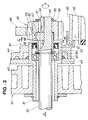
- the one-way clutch 35 includes a swinging clutch portion 53, a clutch portion housing groove 54, a collar 55, a slit 56, engaging grooves 57, and a sealing member 61.
- the swinging clutch portion 53 has a keyhole-section shape, consisting of a cylindrical portion 51 extending in an axially longitudinal direction (directions of arrows "a") of the drive shaft 33 and a projecting portion 52 extending from the periphery of the cylindrical portion 51.
- the clutch portion housing groove 54 is formed in the drive shaft 33 for housing the cylindrical portion 51 of the swinging clutch portion 53, holding the swinging clutch portion 53 swingably.
- the collar 55 is fitted onto the drive shaft 33 rotatably (in directions of arrows "b").
- the collar 55 has the slit 56 formed in an axially longitudinal direction so that the projecting portion 52 of the swinging clutch portion 53 can project therefrom and retract thereinto.
- the engaging grooves 57 are formed in the driven member 36 for engagement with the projecting portion 52.
- the sealing member 61 is interposed between the housing 31 and the collar 55 for preventing the collar 55 from rotating together with the rotation of the drive shaft 33.
- the sealing member 61 is an oil seal, and is desirably provided with a spring 63.
- the drive shaft 33 is rotatably supported by the housing 31 via a bearing 64.
- Reference numerals 65, 65 denote snap rings, and 66, 66, flat rings.
- FIG. 5A illustrates in explosion the power transmission mechanism 32 of the present invention
- FIG. 5B illustrates in section the first end portion 34 of the drive shaft 33 along line 5B ⁇ 5B in FIG. 5A
- FIG. 5C illustrates the swinging clutch portion 53 when viewed along line 5C ⁇ 5C in FIG. 5A.
- the drive shaft 33 has the clutch portion housing groove 54 and circumferential grooves 71, 71 formed in the first end portion 34, and the clutch portion housing groove 54 and circumferential grooves 71, 71 formed in the second end portion 37.
- the snap rings 65, 65 are fitted into the circumferential grooves 71, 71, respectively.
- a steel material defined by S48C in JIS is used, for example.
- the collar 55 has a tubular body 72 of a steel pipe with a given thickness "t,” having at its first end portion the slit 56 formed in an axially longitudinal direction of the tubular body 72. Slitting facilitates fabrication, and also facilitates the assembly of the swinging clutch portion 53.
- a spur gear is used, and the facewidth of the spur gear is set at Wt.
- the driven member 36 may be other than a spur gear, and, for example, a pulley may alternatively be used.
- a sintered material is used, for example.
- Each engaging groove 57 is formed in an inner peripheral surface 75 of the driven member 36 with a length approximately half the facewidth Wt.
- the three engaging grooves 57 are formed in the inner peripheral surface 75 at equal intervals, but the number thereof can be any.
- the clutch portion housing groove 54 consists of a circular portion 77 into which the cylindrical portion 51 of the swinging clutch portion 53 is fitted, and a linear portion 78 extending continuously from the circular portion 77 to the periphery of the drive shaft 33.
- the clutch portion housing groove 54 is formed at a position radially offset from the center O of the drive shaft 33, serving as a cam groove.
- the swinging clutch portion 53 has a keyhole-section shape, consisting of the cylindrical portion 51 and the projecting portion 52 extending from the cylindrical portion 51, as described above.
- the projecting portion 52 has inclined portions 81, 81 formed at its distal end portion.
- the formation of the inclined portions 81, 81 makes it possible to reduce the depth "h" of each engaging groove 57 to be engaged with the projecting portion 52 (see FIG. 4) to reduce the size of the engaging grooves 57, and also makes it possible to form the corners of the engaging grooves 57 at an obtuse angle to facilitate forming of the engaging grooves 57.
- a sintered material is used for the material of the swinging clutch portion 53.
- FIGS. 6A to 6E illustrate the one-way clutch 35 from the state of not transmitting a driving force from the drive shaft 33 to the driven member 36 (non-engagement state) to the state of transmitting a driving force (engagement state).
- the one-way clutch 35 is in a non-engagement state, not transmitting a driving force from the drive shaft 33 to the driven member 36.
- the swinging clutch portion 53 of the one-way clutch 35 moves down at angle ⁇ 1 to be within the clutch portion housing groove 54, and at the same time, the distal end portion of the projecting portion 52 of the clutch portion 53 retracts into the slit 56 of the collar 55.
- the distal end portion of the projecting portion 52 does not engage any engaging groove 57, and the one-way clutch 35 does not transmit power to the driven member 36. That is, the projecting portion 52 in a linear shape of the swinging clutch portion 53 lies down in contact with the linear portion 78 of the clutch portion housing groove 54.
- the drive shaft 33 continuously rotates the collar 55 via the swinging clutch portion 53. While the drive shaft 33 and the collar 55 rotate together, the driven member 36 does not rotate and continues stationary.
- the cylindrical portion 51 of the swinging clutch portion 53 is rotated by the collar 55 at angle ⁇ 2 as shown by arrow "h," and the projecting portion 52 is detached from the linear portion 78 of the clutch portion housing groove 54, raised by angle ⁇ 2. That is, the collar 55 rotating more slowly than the drive shaft 33 raises the swinging clutch portion 53 to bring the clutch 35 into an engaged state.
- the one-way clutch 35 is in a state of being able to transmit a driving force (engagement state), and a driving force is transmitted from the drive shaft 33 to the driven member 36 as shown by arrow "j." With the rotation of the drive shaft 33, the driven member 36 also rotates.
- the one-way clutch 35 has an advantage that, as shown in FIG. 6C, the projecting portion 52 can be swung by angle 02, pivoting on the cylindrical portion 51 of the swinging clutch portion 53, and thereby ensuring transmission of power without impacts.
- the one-way clutch 35 has the sealing member 61 interposed between the housing 31 and the collar 55 as shown in FIG. 3, thus facilitating the provision of rotation resistance to the collar 55 with the sealing member 61 of a simple configuration.
- FIGS. 7A to 7D illustrate the operation of the one-way clutch 35 when the lawn mower 11 (see FIG. 1) is turned when being driven by the engine 15 (see FIG. 1), that is, the operation of the one-way clutch 35 from a state of transmitting a driving force (engagement state) to a state of not transmitting a driving force (non-engagement state).
- these figures show those states with the drive shaft 33 not rotated.
- the one-way clutch 35 is engaged, transmitting a driving force from the drive shaft 33 to the driven member 36, driving the drive wheel 22 (see FIG. 1).
- Nd the number of revolutions of the drive shaft 33
- the number of revolutions of the driven member 36 is increased from Ng to Nf relative to the number of revolutions Nd of the drive shaft 33 (Nf > Nd), and the engaging groove 57 of the driven member 36 rotates without interfering with the projecting portion 52, allowing the driven member 36 to rotate faster than the drive shaft 33.
- the operation of increasing the number of revolutions of the driven member 36 is done by rotating the drive wheel 22 (see FIG. 1) by pushing the operating handle 14 (see FIG. 1).
- the driven member 36 can be rotated in a direction (direction of arrow "j"), here, a forward direction, by a small force.
- the driven member 36 rotates in a direction in the same manner. That is, the drive wheel 22 (see FIG. 1) can be rotated in a direction.
- an operator can move the lawn mower 11 forward by a small force.
- FIGS. 8A to 8C schematically illustrate straight traveling and turning states of the lawn mower 11.
- the lawn mower 11 shown in FIG. 8A is advanced by an operator manually pushing the lawn mower 11 without starting the engine 15. As described with FIGS. 7A to 7D, since the one-way clutches 35 do not engage the driven members 36 and the drive wheels 22, 22 rotate freely, the lawn mower 11 can be easily pushed and moved forward by hand.
- FIG. 8B illustrates a state where the engine 15 is started. Since the driving force of the engine 15 is transmitted to the right and left drive wheels 22, 22 via the one-way clutches 35, 35 as described with FIGS. 6A to 6E, an operator can cause the lawn mower 11 to move straight.
- the power transmission mechanisms of the present invention are exemplarily applied to a lawn mower for description, but are also applicable to one-wheel to four-wheel carriers, cultivators and snow plows.
Abstract
Description
- The present invention relates to power transmission mechanisms employing a one-way clutch in a drivetrain.
- One-way clutches, which transmit power in a fixed direction, are, for example, provided at right and left ends of a drive shaft of a self-propelled walk-behind lawn mower in order to facilitate turning of the lawn mower and allow the lawn mower, when moved with an engine stopped, to be easily pushed and moved by hand (see, e.g., U.S. Patent No. 4909365 and Japanese Patent Laid-Open Publication No. 2001-59531).
- First, a freewheel clutch disclosed in U.S. Patent No. 4909365 will be described with reference to FIG. 9.
- Referring to FIG. 9, a
clutch mechanism 100 is used for transmitting a driving force of adrive shaft 101 to apinion 102. Theclutch mechanism 100 includes, as its main elements, akey 103 and afriction disc 104. Thekey 103 has awedge portion 103a to be received in afirst keyway 105 axially formed in thedrive shaft 101, in such a manner as to be able to rock therein to extend therefrom and retract thereinto, and a projectingportion 103b to be received in a hollowedportion 104a formed in thefriction disc 104. Thewedge portion 103a has a thick side portion forming anengaging portion 103c. - When the
drive shaft 101 is rotated, thekey 103 is simultaneously rotated, causing the projectingportion 103b of thekey 103 to abut on the hollowedportion 104a of thefriction disc 104. Since thefriction disc 104 is in frictional engagement with ahousing 106, the projectingportion 103b of thekey 103 is not moved further. Thus, thewedge portion 103a of thekey 103 is cocked, projecting from within thefirst keyway 105. Theengaging portion 103c of thewedge portion 103a engages one of a plurality ofsecond keyways 102a formed in the inner peripheral surface of thepinion 102, thereby ensuring transmission of a driving force of thedrive shaft 101 to thepinion 102. - When the
drive shaft 101 is not rotated, thewedge portion 103a of thekey 103 is received within thefirst keyway 105 without being cocked, and thepinion 102 can rotate bidirectionally relative to thedrive shaft 101. - The
above clutch mechanism 100, however, has a problem that, for producing rotation resistance at thefriction disc 104 by athrust spring 107, it is necessary to reduce variations in friction coefficient between the surface of thehousing 106, the opposite surfaces of thefriction disc 104 and the surface of thepinion 102, resulting in time-consuming surface treatment of these components. - Second, a power transmission mechanism disclosed in Japanese Patent Laid Open Publication No. 2001-59531 will be described with reference to FIGS. 10A to 10C.
- A
power transmission mechanism 200 shown in FIG. 10A includes adrive shaft 201, a plurality of pins 203 (three in the illustrated example) fitted in a plurality ofcam grooves 202 formed in thedrive shaft 201, agear 204 and afriction disc 205 fitted onto thedrive shaft 201, and anoil seal 206 fitted onto thefriction disc 205. When thedrive shaft 201 is not rotated, thepins 203 are detached from the inner peripheral surface of thegear 204 forming ahole 207, allowing thegear 204 to rotate bidirectionally relative to thedrive shaft 201. - The above
power transmission mechanism 200, however, requires highly accurate formation of the surfaces constituting thecam grooves 202, the outer peripheral surfaces of thepins 203 and the inner peripheral surface of thegear hole 207. Specifically, as shown in FIGS. 10B and 10C, it is necessary to set the dimensional tolerance of thecam grooves 202 and thepins 203 small. If not, excessive or insufficient contact can occur between the threepins 203 and thegear hole 207, causing thepins 203 to be likely to have serpentine behavior, sliding and suffering great impacts when transmitting power. - Thus, it is desired to ensure transmission of power without impacts by a simple configuration having no need to set the accuracy of fabricating each component at a high degree.
- According to the present invention, there is provided a power transmission mechanism, which comprises: a drive shaft rotatably supported by housings, at least a first end portion of which drive shaft projecting from the corresponding housing; and a driven member mounted on the projecting first end portion of the drive shaft with a one-way clutch interposed therebetween; the one-way clutch comprising: a swinging clutch portion in a keyhole-section shape, including a cylindrical portion extending axially of the drive shaft and a projecting portion extending from the cylindrical portion; a clutch portion housing groove formed in the drive shaft, for housing the cylindrical portion, holding the swinging clutch portion swingably about the cylindrical portion; a collar rotatably fitted onto the drive shaft, having a slit formed in such a manner that a distal end portion of the projecting portion can project therefrom and retract thereinto; at least one engaging groove formed in an inner peripheral surface of the driven member to engage the distal end portion of the projecting portion; and a sealing member interposed between the housing and the collar for preventing the collar from rotating together with rotation of the drive shaft; wherein, when the swinging clutch portion is raised by the collar rotating more slowly than the drive shaft rotates, the distal end portion of the projecting portion projects from a periphery of the slit, thereby engaging the engaging groove; and when the swinging clutch portion is laid down, the distal end portion of the projecting portion retracts into the slit, thereby disengaging from the engaging groove.
- The one-way clutch is thus simply configured only by making the clutch portion housing groove in a circular groove corresponding to the cylindrical portion, making the swinging clutch portion in a combined shape of a cylinder and a prism, forming the collar in a steel pipe shape, and forming the slit correspondingly to the projecting portion, thereby favorably eliminating the need for setting the accuracy of fabricating each component at a high degree.
- Further, the projecting portion can be swung with the cylindrical portion of the swinging clutch portion fitted in the clutch portion housing groove of the drive shaft as the pivot in close contact with the clutch portion housing groove, providing an advantage of securely transmitting power without impacts.
- The clutch portion housing groove formed in the drive shaft is preferably formed at a position radially offset from a shaft center of the drive shaft.
- Preferred embodiments of the present invention will be described in detail below, by way of example only, with reference to the accompanying drawings, in which:
- FIG. 1 is a side view of a lawn mower employing power transmission mechanisms of the present invention;
- FIG. 2 is a cross-sectional view of a mechanism in which a driving force from a drive shaft is transmitted to right and left rear wheels via the power transmission mechanisms of the present invention;
- FIG. 3 is an enlarged cross-sectional view of
portion 3 in FIG. 2 of the power transmission mechanism; - FIG. 4 is a cross-sectional view taken along line 4―4 in FIG. 3;
- FIG. 5A is an exploded view of the power transmission mechanism
shown in FIG. 3; FIG. 5B is a cross-sectional view along
line 5B―5B in FIG. 5A; and FIG. 5C is a front view of a swinging clutch portion alongline 5C―5C in FIG. 5A; - FIGS. 6A to 6E are diagrams illustrating the operation of a one-way clutch portion and a driven member of the power transmission mechanism of the present invention from the state of non-engagement to the state of engagement;
- FIGS. 7A to 7D are diagrams illustrating the operation of the one-way clutch portion and the driven member of the power transmission mechanism from the state of engagement to the state of non-engagement;
- FIGS. 8A to 8C are schematic diagrams illustrating a straight advancing state and a turning state of the lawn mower employing the power transmission mechanisms of the present invention;
- FIG. 9 is a perspective view of the basic structure of a conventional freewheel clutch; and
- FIGS. 10A to 10C are diagrams illustrating the basic structure and function of a conventional power-transmission mechanism.
-
- For the description of the present embodiment, a lawn mower will be exemplarily illustrated as an embodiment employing power transmission mechanisms according to the present invention.
- A
lawn mower 10 shown in FIG. 1 is a walk-behind self-propelled lawn mower with which an operator mows, walking behind thelawn mower 10. - The
lawn mower 10 includes abody frame 12, right and leftfront wheels 13 mounted to the body frame 12 (the rightfront wheel 13 is not shown because FIG. 1 is a view of thelawn mower 10 taken from one side), anengine 15 mounted on an upper middle portion of thebody frame 12, acutting blade 18 connected to anoutput shaft 17 of theengine 15, adrive unit 21 connected to theoutput shaft 17, and right andleft drive wheels 22 as rear wheels connected to the drive unit 21 (only the leftrear wheel 22 is shown as described with the front wheels 13). - An
operating handle 14 extends obliquely from the rear of thebody frame 12 in a rearward and upward direction. - The
cutting blade 18 is housed in acutter housing 16 mounted to a lower middle portion of thebody frame 12. - The
drive unit 21 includes adriving pulley 24 mounted on theoutput shaft 17, a drivenpulley 26, abelt 25 running between thedriving pulley 24 and the drivenpulley 26, adrive reduction gear 27 mounted to thebody frame 12 and connected to the drivenpulley 26, right and left wheel support means 28 (see FIG. 2) mounted to thebody frame 12, right and left tubular housings 31 (see FIG. 2) fitted to thebody frame 12, and right and leftpower transmission mechanisms 32, 32 (see FIG. 2) connected to thedrive reduction gear 27. - As shown in FIG. 2, the
drive shaft 33 is provided between the right and leftpower transmission mechanisms 32 with thedrive reduction gear 27 interposed therebetween. The opposite ends of thedrive shaft 33 are rotatably fitted in the right and lefttubular housings 31, respectively. A first end (right end)portion 34 of thedrive shaft 33 is projected from theright housing 31. A second end (left end)portion 37 of thedrive shaft 33 is projected from theleft housing 31. - Right and left driven
members 36 are mounted on thefirst end portion 34 and thesecond end portion 37 of thedrive shaft 33, respectively, with right and left one-way clutches 35 interposed therebetween. - The right and left
power transmission mechanisms 32 transmit power from thedrive shaft 33, through the drivenmembers left drive wheels Reference numeral 38 denotes a wheel of thedrive wheels 22. - Each wheel support means 28 includes a
bracket 42 fixed at its first end to thehousing 31 and fitted at its second end to thebody frame 12, anaxle 43 fixed to thebracket 42, acover 44 mounted to theaxle 43 and thehousing 31, and agear 45 mounted on a boss of thewheel 38, meshing with the drivenmember 36 provided with the one-way clutch 35. - Now, one of the one-
way clutches 35 will be described with reference to FIGS. 3 and 4. - The one-
way clutch 35 includes a swingingclutch portion 53, a clutchportion housing groove 54, acollar 55, aslit 56,engaging grooves 57, and a sealingmember 61. - The swinging
clutch portion 53 has a keyhole-section shape, consisting of acylindrical portion 51 extending in an axially longitudinal direction (directions of arrows "a") of thedrive shaft 33 and a projectingportion 52 extending from the periphery of thecylindrical portion 51. - The clutch
portion housing groove 54 is formed in thedrive shaft 33 for housing thecylindrical portion 51 of the swingingclutch portion 53, holding the swingingclutch portion 53 swingably. - The
collar 55 is fitted onto thedrive shaft 33 rotatably (in directions of arrows "b"). Thecollar 55 has theslit 56 formed in an axially longitudinal direction so that the projectingportion 52 of the swingingclutch portion 53 can project therefrom and retract thereinto. - The engaging
grooves 57 are formed in the drivenmember 36 for engagement with the projectingportion 52. - The sealing
member 61 is interposed between thehousing 31 and thecollar 55 for preventing thecollar 55 from rotating together with the rotation of thedrive shaft 33. The sealingmember 61 is an oil seal, and is desirably provided with aspring 63. - The
drive shaft 33 is rotatably supported by thehousing 31 via abearing 64.Reference numerals - As shown in FIG. 4, in the one-way clutch 35, when the
drive shaft 33 rotates in a direction of arrow "d," the swingingclutch portion 53 engages one of the engaginggrooves 57, transmitting power to the drivenmember 36 as shown by arrow "e." - FIG. 5A illustrates in explosion the
power transmission mechanism 32 of the present invention; FIG. 5B illustrates in section thefirst end portion 34 of thedrive shaft 33 alongline 5B―5B in FIG. 5A; and FIG. 5C illustrates the swingingclutch portion 53 when viewed alongline 5C―5C in FIG. 5A. - As shown in FIG. 5A, the
drive shaft 33 has the clutchportion housing groove 54 andcircumferential grooves first end portion 34, and the clutchportion housing groove 54 andcircumferential grooves second end portion 37. The snap rings 65, 65 are fitted into thecircumferential grooves - For the
drive shaft 33, a steel material defined by S48C in JIS is used, for example. - The
collar 55 has atubular body 72 of a steel pipe with a given thickness "t," having at its first end portion theslit 56 formed in an axially longitudinal direction of thetubular body 72. Slitting facilitates fabrication, and also facilitates the assembly of the swingingclutch portion 53. - For the driven
member 36, a spur gear is used, and the facewidth of the spur gear is set at Wt. The drivenmember 36 may be other than a spur gear, and, for example, a pulley may alternatively be used. For the material of the drivenmember 36, a sintered material is used, for example. - Each engaging
groove 57 is formed in an innerperipheral surface 75 of the drivenmember 36 with a length approximately half the facewidth Wt. In the embodiment shown in the figure, the threeengaging grooves 57 are formed in the innerperipheral surface 75 at equal intervals, but the number thereof can be any. - As shown in FIG. 5B, the clutch
portion housing groove 54 consists of acircular portion 77 into which thecylindrical portion 51 of the swingingclutch portion 53 is fitted, and alinear portion 78 extending continuously from thecircular portion 77 to the periphery of thedrive shaft 33. The clutchportion housing groove 54 is formed at a position radially offset from the center O of thedrive shaft 33, serving as a cam groove. - As shown in FIG. 5C, the swinging
clutch portion 53 has a keyhole-section shape, consisting of thecylindrical portion 51 and the projectingportion 52 extending from thecylindrical portion 51, as described above. The projectingportion 52 has inclinedportions inclined portions groove 57 to be engaged with the projecting portion 52 (see FIG. 4) to reduce the size of the engaginggrooves 57, and also makes it possible to form the corners of the engaginggrooves 57 at an obtuse angle to facilitate forming of the engaginggrooves 57. For the material of the swingingclutch portion 53, a sintered material is used. - Now, the operation of the one-way clutch 35 will be described with reference to FIGS. 6A to 6E and FIGS. 7A to 7D.
- FIGS. 6A to 6E illustrate the one-way clutch 35 from the state of not transmitting a driving force from the
drive shaft 33 to the driven member 36 (non-engagement state) to the state of transmitting a driving force (engagement state). - First, in FIG. 6A, the one-way clutch 35 is in a non-engagement state, not transmitting a driving force from the
drive shaft 33 to the drivenmember 36. Specifically, the swingingclutch portion 53 of the one-way clutch 35 moves down at angle 1 to be within the clutchportion housing groove 54, and at the same time, the distal end portion of the projectingportion 52 of theclutch portion 53 retracts into theslit 56 of thecollar 55. Thus, the distal end portion of the projectingportion 52 does not engage any engaginggroove 57, and the one-way clutch 35 does not transmit power to the drivenmember 36. That is, the projectingportion 52 in a linear shape of the swingingclutch portion 53 lies down in contact with thelinear portion 78 of the clutchportion housing groove 54. - When the engine 15 (see FIG. 1) of the lawn mower 11 is started and the
drive shaft 33 starts rotating in a direction shown by arrow "f," the distal end portion of the projectingportion 52 of the swingingclutch portion 53 fitted in the clutchportion housing groove 54 of thedrive shaft 33 abuts on the innerperipheral surface 75 of the drivenmember 36, being caught on theslit 56 of thecollar 55, and thecollar 55 starts rotating in a direction shown by arrow "g." At that time, thecollar 55 rotates against the fastening force of the sealing member 61 (see FIG. 3). - Referring to FIG. 6B, the
drive shaft 33 continuously rotates thecollar 55 via the swingingclutch portion 53. While thedrive shaft 33 and thecollar 55 rotate together, the drivenmember 36 does not rotate and continues stationary. - In FIG. 6C, the
drive shaft 33 and thecollar 55 continue rotating, and when theslit 56 of thecollar 55 and the projectingportion 52 of the swingingclutch portion 53 together reach one of the engaginggrooves 57 of the drivenmember 36, the distal end portion of the projectingportion 52 enters the engaginggroove 57. Specifically, while thecollar 55 is being stopped or rotated with a lag due to the fastening force of the sealingmember 61, the distal end portion of the projectingportion 52 enters the engaginggroove 57 by the continuously rotatingdrive shaft 33. In other words, thecylindrical portion 51 of the swingingclutch portion 53 is rotated by thecollar 55 at angle 2 as shown by arrow "h," and the projectingportion 52 is detached from thelinear portion 78 of the clutchportion housing groove 54, raised by angle 2. That is, thecollar 55 rotating more slowly than thedrive shaft 33 raises the swingingclutch portion 53 to bring the clutch 35 into an engaged state. - In FIG. 6D, the
drive shaft 33 continues rotating, and when thedrive shaft 33, thecollar 55 and the swinging clutch portion 53 (projecting portion 52) rotate together by angle β approximately corresponding to the width of the bottom 76 of the engaginggroove 57, the distal end portion of the projectingportion 52 engages the engaginggroove 57, and the one-way clutch 35 is in an engaged state. - In FIG. 6E, the one-way clutch 35 is in a state of being able to transmit a driving force (engagement state), and a driving force is transmitted from the
drive shaft 33 to the drivenmember 36 as shown by arrow "j." With the rotation of thedrive shaft 33, the drivenmember 36 also rotates. - As described above, the one-way clutch 35 has an advantage that, as shown in FIG. 6C, the projecting
portion 52 can be swung by angle 02, pivoting on thecylindrical portion 51 of the swingingclutch portion 53, and thereby ensuring transmission of power without impacts. - The one-way clutch 35 has the sealing
member 61 interposed between thehousing 31 and thecollar 55 as shown in FIG. 3, thus facilitating the provision of rotation resistance to thecollar 55 with the sealingmember 61 of a simple configuration. - FIGS. 7A to 7D illustrate the operation of the one-way clutch 35 when the lawn mower 11 (see FIG. 1) is turned when being driven by the engine 15 (see FIG. 1), that is, the operation of the one-way clutch 35 from a state of transmitting a driving force (engagement state) to a state of not transmitting a driving force (non-engagement state). For ease of explanation, these figures show those states with the
drive shaft 33 not rotated. - In FIG. 7A, the one-way clutch 35 is engaged, transmitting a driving force from the
drive shaft 33 to the drivenmember 36, driving the drive wheel 22 (see FIG. 1). With the number of revolutions of thedrive shaft 33 as Nd, and with the number or revolutions of the drivenmember 36 as Ng, the number of revolutions Nd of thedrive shaft 33 is equal to the number of revolutions Ng of the driven member 36 (Nd = Ng). - In FIG. 7B, the number of revolutions of the driven
member 36 is increased from Ng to Nf relative to the number of revolutions Nd of the drive shaft 33 (Nf > Nd), and the engaginggroove 57 of the drivenmember 36 rotates without interfering with the projectingportion 52, allowing the drivenmember 36 to rotate faster than thedrive shaft 33. The operation of increasing the number of revolutions of the drivenmember 36 is done by rotating the drive wheel 22 (see FIG. 1) by pushing the operating handle 14 (see FIG. 1). - In FIG. 7C, the driven
member 36 is continuously rotated at the number of revolutions Nf, and the engaginggroove 57 interferes with the projectingportion 52, causing thecollar 55 to rotate together with the projectingportion 52 interfered as shown by arrows "k" and "m" against the fastening force of the sealing member 61 (see FIG. 3). With the rotation of thecollar 55, the swingingclutch portion 53 starts moving downward gradually (in the direction of arrow "k"). - In FIG. 7D, with the rotation of the
collar 55, the swingingclutch portion 53 moves down by angle γ, and the projectingportion 52 of theclutch portion 53 abuts on thelinear portion 78 of the clutchportion housing groove 54, and at the same time, the distal end portion of the projectingportion 52 retracts into theslit 56. Thus, the swingingclutch portion 53 does not engage the drivenmember 36. In other words, the swingingclutch portion 53 is moved down by thecollar 55 by angle γ as shown by arrow "k," bringing the clutch 35 into a non-engagement state. That is, the swingingclutch portion 53 is laid down to disengage the clutch 35. - As a result, without receiving a rotational driving force of the
drive shaft 33, the drivenmember 36 can be rotated in a direction (direction of arrow "j"), here, a forward direction, by a small force. - When the
drive shaft 33 is not rotated, the drivenmember 36 rotates in a direction in the same manner. That is, the drive wheel 22 (see FIG. 1) can be rotated in a direction. When manually advancing the lawn mower 11, an operator can move the lawn mower 11 forward by a small force. - FIGS. 8A to 8C schematically illustrate straight traveling and turning states of the lawn mower 11.
- The lawn mower 11 shown in FIG. 8A is advanced by an operator manually pushing the lawn mower 11 without starting the
engine 15. As described with FIGS. 7A to 7D, since the one-way clutches 35 do not engage the drivenmembers 36 and thedrive wheels - FIG. 8B illustrates a state where the
engine 15 is started. Since the driving force of theengine 15 is transmitted to the right and leftdrive wheels way clutches - In FIG. 8C, since the driving force of the
engine 15 is not transmitted to theleft drive wheel 22 by the one-way clutch 35 as described with FIGS. 7A to 7D, it is easy for an operator to increase the number of revolutions of theleft drive wheel 22, and the operator can easily turn the lawn mower 11 right. - In this embodiment, the power transmission mechanisms of the present invention are exemplarily applied to a lawn mower for description, but are also applicable to one-wheel to four-wheel carriers, cultivators and snow plows.
Claims (2)
- A power transmission mechanism comprising:wherein, when the swinging clutch portion is raised by the collar rotating more slowly than the drive shaft rotates, the distal end portion of the projecting portion projects from a periphery of the slit, thereby engaging the engaging groove, and when the swinging clutch portion is laid down, the distal end portion of the projecting portion retracts into the slit, thereby disengaging from the engaging groove.a drive shaft (33) rotatably supported by housings (31), at least one end portion of the drive shaft projecting from the corresponding housing; anda driven member (36) mounted on the projecting one end portion of the drive shaft by means of a one-way clutch (35) interposed therebetween;the one-way clutch comprising:a swinging clutch portion (53) of keyhole-section shape, including a cylindrical portion (51) extending axially of the drive shaft and a projecting portion (52) extending from the cylindrical portion;a clutch portion housing groove (54) formed in the drive shaft (33), for housing the cylindrical portion (51), holding the swinging clutch portion (53) swingably about the cylindrical portion;a collar (55) rotatably fitted onto the drive shaft and having a slit (56) formed such that a distal end portion of the projecting portion (52) can project therefrom and retract thereinto;at least one engaging groove (57) formed in an inner peripheral surface of the driven member (36) for engagement with the distal end portion of the projecting portion (52); anda sealing member (61) interposed between the housing (31) and the collar for preventing the collar (55) from rotating along with rotation of the drive shaft (33),
- The power transmission mechanism of claim 1, wherein the clutch portion housing groove (54) formed in the drive shaft (33) is provided at a position radially offset from a shaft center (O) of the drive shaft.
Applications Claiming Priority (2)
| Application Number | Priority Date | Filing Date | Title |
|---|---|---|---|
| JP2003365222 | 2003-10-24 | ||
| JP2003365222A JP2005127448A (en) | 2003-10-24 | 2003-10-24 | Power transmission mechanism |
Publications (3)
| Publication Number | Publication Date |
|---|---|
| EP1526300A2 true EP1526300A2 (en) | 2005-04-27 |
| EP1526300A3 EP1526300A3 (en) | 2007-03-28 |
| EP1526300B1 EP1526300B1 (en) | 2008-07-09 |
Family
ID=34386551
Family Applications (1)
| Application Number | Title | Priority Date | Filing Date |
|---|---|---|---|
| EP04255588A Expired - Fee Related EP1526300B1 (en) | 2003-10-24 | 2004-09-15 | Power transmission mechanism |
Country Status (7)
| Country | Link |
|---|---|
| US (1) | US7073648B2 (en) |
| EP (1) | EP1526300B1 (en) |
| JP (1) | JP2005127448A (en) |
| CN (2) | CN1325815C (en) |
| AU (1) | AU2004218605B2 (en) |
| CA (1) | CA2482218C (en) |
| DE (1) | DE602004014873D1 (en) |
Cited By (1)
| Publication number | Priority date | Publication date | Assignee | Title |
|---|---|---|---|---|
| EP1860340A1 (en) * | 2006-05-24 | 2007-11-28 | HONDA MOTOR CO., Ltd. | Travel-driving mechanism for self-propelled working machine |
Families Citing this family (9)
| Publication number | Priority date | Publication date | Assignee | Title |
|---|---|---|---|---|
| JP2005127448A (en) * | 2003-10-24 | 2005-05-19 | Honda Motor Co Ltd | Power transmission mechanism |
| DK177273B1 (en) * | 2008-02-11 | 2012-09-10 | Hh Patent As | Clutch |
| JP5041248B2 (en) * | 2008-10-23 | 2012-10-03 | アイシン精機株式会社 | Self-locking clutch |
| WO2011067815A1 (en) * | 2009-12-03 | 2011-06-09 | トヨタ自動車株式会社 | Torque fluctuation absober |
| KR101735465B1 (en) * | 2015-11-25 | 2017-05-15 | 현대다이모스(주) | Actuator System For Dual Clutch |
| JP6230642B2 (en) * | 2016-03-17 | 2017-11-15 | 本田技研工業株式会社 | Walking lawn mower |
| US10550899B2 (en) * | 2018-03-30 | 2020-02-04 | Honda Motor Co. | Transmission for wheeled machine |
| CN113819157B (en) * | 2021-09-29 | 2023-04-28 | 延锋汽车智能安全系统有限责任公司 | One-way clutch and seatbelt retractor |
| CN113819158B (en) * | 2021-09-29 | 2023-08-15 | 延锋汽车智能安全系统有限责任公司 | One-way clutch and seatbelt retractor |
Citations (2)
| Publication number | Priority date | Publication date | Assignee | Title |
|---|---|---|---|---|
| US4909365A (en) | 1987-07-02 | 1990-03-20 | The Toro Company | Freewheeling clutch and implement employing same |
| JP2001059531A (en) | 1999-06-16 | 2001-03-06 | Honda Motor Co Ltd | Clutch mechanism |
Family Cites Families (5)
| Publication number | Priority date | Publication date | Assignee | Title |
|---|---|---|---|---|
| JPS60227025A (en) * | 1984-04-25 | 1985-11-12 | Asahi Optical Co Ltd | Clutch mechanism |
| US4928905A (en) * | 1989-05-01 | 1990-05-29 | Arena Recreations (Toronto) Limited | One-way clutch assembly |
| US6354414B1 (en) * | 1999-06-16 | 2002-03-12 | Honda Giken Kogyo Kabushiki Kaisha | Clutch mechanism |
| US6575280B2 (en) * | 2001-06-11 | 2003-06-10 | White Consolidated Industries, Inc. | Freewheeling bi-directional clutch |
| JP2005127448A (en) * | 2003-10-24 | 2005-05-19 | Honda Motor Co Ltd | Power transmission mechanism |
-
2003
- 2003-10-24 JP JP2003365222A patent/JP2005127448A/en active Pending
-
2004
- 2004-09-15 DE DE602004014873T patent/DE602004014873D1/en active Active
- 2004-09-15 EP EP04255588A patent/EP1526300B1/en not_active Expired - Fee Related
- 2004-09-21 CA CA2482218A patent/CA2482218C/en not_active Expired - Fee Related
- 2004-09-24 US US10/949,954 patent/US7073648B2/en not_active Expired - Fee Related
- 2004-10-04 AU AU2004218605A patent/AU2004218605B2/en not_active Ceased
- 2004-10-22 CN CNB200410087719XA patent/CN1325815C/en not_active Expired - Fee Related
- 2004-10-22 CN CNU2004201049483U patent/CN2766107Y/en not_active Expired - Lifetime
Patent Citations (2)
| Publication number | Priority date | Publication date | Assignee | Title |
|---|---|---|---|---|
| US4909365A (en) | 1987-07-02 | 1990-03-20 | The Toro Company | Freewheeling clutch and implement employing same |
| JP2001059531A (en) | 1999-06-16 | 2001-03-06 | Honda Motor Co Ltd | Clutch mechanism |
Cited By (2)
| Publication number | Priority date | Publication date | Assignee | Title |
|---|---|---|---|---|
| EP1860340A1 (en) * | 2006-05-24 | 2007-11-28 | HONDA MOTOR CO., Ltd. | Travel-driving mechanism for self-propelled working machine |
| US7777444B2 (en) | 2006-05-24 | 2010-08-17 | Honda Motor Co., Ltd. | Travel-driving mechanism for self-propelled working machine |
Also Published As
| Publication number | Publication date |
|---|---|
| AU2004218605B2 (en) | 2011-01-27 |
| EP1526300A3 (en) | 2007-03-28 |
| CA2482218A1 (en) | 2005-04-24 |
| CN1609469A (en) | 2005-04-27 |
| EP1526300B1 (en) | 2008-07-09 |
| CN1325815C (en) | 2007-07-11 |
| US7073648B2 (en) | 2006-07-11 |
| US20050087418A1 (en) | 2005-04-28 |
| CA2482218C (en) | 2010-07-27 |
| JP2005127448A (en) | 2005-05-19 |
| AU2004218605A1 (en) | 2005-05-12 |
| CN2766107Y (en) | 2006-03-22 |
| DE602004014873D1 (en) | 2008-08-21 |
Similar Documents
| Publication | Publication Date | Title |
|---|---|---|
| CN108700128B (en) | The double rolling key clutch with outer spring for drive shaft | |
| EP0782820B1 (en) | Transmission for self-propelled walking lawn mower | |
| EP1526300B1 (en) | Power transmission mechanism | |
| US7490708B2 (en) | Automatic traction enhancement for a transaxle | |
| EP0298016B1 (en) | Freewheeling clutch and implement employing same | |
| FR2885656A1 (en) | Gearbox for e.g. self-powered lawnmower, has clutch engaging mechanisms arranged between drive wheel and two main drive shafts of wheels of rolling vehicle, where each mechanism cooperates with shafts to set wheels of vehicle in free wheel | |
| US8052556B2 (en) | Apparatuses and methods for controlling a variable speed transmission | |
| US6354414B1 (en) | Clutch mechanism | |
| CN111788406B (en) | Transmission device of wheeled machine | |
| EP3959449B1 (en) | Transmission box and engine equipped with such a transmission box | |
| US20060183582A1 (en) | Transmission system for a self-propelled vehicle with variable travel speed, its control device, and vehicle equipped with such a transmission system | |
| US7070035B2 (en) | Two-way coupling apparatus and method | |
| JP3294101B2 (en) | Seedling planting mechanism | |
| JP2001059531A (en) | Clutch mechanism | |
| JPS62441Y2 (en) | ||
| JP2023034443A (en) | Rotating direction switching mechanism of mowing blade, self-propelling mowing machine, and mowing method | |
| JP2678987B2 (en) | Power transmission device including speed change mechanism of self-propelled working machine | |
| JPH10299790A (en) | Clutch device of mobile working machine | |
| JP3832958B2 (en) | Portable brush cutter | |
| JPH0542574B2 (en) | ||
| JP2000354401A (en) | Tending machine | |
| JPS6021549Y2 (en) | clutch structure | |
| JPH09256935A (en) | One-way cluth and starter having it | |
| JPH0431139Y2 (en) | ||
| JPH04110234U (en) | rotation transmission device |
Legal Events
| Date | Code | Title | Description |
|---|---|---|---|
| PUAI | Public reference made under article 153(3) epc to a published international application that has entered the european phase |
Free format text: ORIGINAL CODE: 0009012 |
|
| AK | Designated contracting states |
Kind code of ref document: A2 Designated state(s): AT BE BG CH CY CZ DE DK EE ES FI FR GB GR HU IE IT LI LU MC NL PL PT RO SE SI SK TR |
|
| AX | Request for extension of the european patent |
Extension state: AL HR LT LV MK |
|
| PUAL | Search report despatched |
Free format text: ORIGINAL CODE: 0009013 |
|
| AK | Designated contracting states |
Kind code of ref document: A3 Designated state(s): AT BE BG CH CY CZ DE DK EE ES FI FR GB GR HU IE IT LI LU MC NL PL PT RO SE SI SK TR |
|
| AX | Request for extension of the european patent |
Extension state: AL HR LT LV MK |
|
| 17P | Request for examination filed |
Effective date: 20070711 |
|
| GRAP | Despatch of communication of intention to grant a patent |
Free format text: ORIGINAL CODE: EPIDOSNIGR1 |
|
| AKX | Designation fees paid |
Designated state(s): DE FR GB IT |
|
| GRAS | Grant fee paid |
Free format text: ORIGINAL CODE: EPIDOSNIGR3 |
|
| GRAA | (expected) grant |
Free format text: ORIGINAL CODE: 0009210 |
|
| AK | Designated contracting states |
Kind code of ref document: B1 Designated state(s): DE FR GB IT |
|
| REG | Reference to a national code |
Ref country code: GB Ref legal event code: FG4D |
|
| REF | Corresponds to: |
Ref document number: 602004014873 Country of ref document: DE Date of ref document: 20080821 Kind code of ref document: P |
|
| PLBE | No opposition filed within time limit |
Free format text: ORIGINAL CODE: 0009261 |
|
| STAA | Information on the status of an ep patent application or granted ep patent |
Free format text: STATUS: NO OPPOSITION FILED WITHIN TIME LIMIT |
|
| 26N | No opposition filed |
Effective date: 20090414 |
|
| PGFP | Annual fee paid to national office [announced via postgrant information from national office to epo] |
Ref country code: FR Payment date: 20100921 Year of fee payment: 7 Ref country code: IT Payment date: 20100918 Year of fee payment: 7 |
|
| PGFP | Annual fee paid to national office [announced via postgrant information from national office to epo] |
Ref country code: GB Payment date: 20100916 Year of fee payment: 7 |
|
| PGFP | Annual fee paid to national office [announced via postgrant information from national office to epo] |
Ref country code: DE Payment date: 20100908 Year of fee payment: 7 |
|
| GBPC | Gb: european patent ceased through non-payment of renewal fee |
Effective date: 20110915 |
|
| PG25 | Lapsed in a contracting state [announced via postgrant information from national office to epo] |
Ref country code: IT Free format text: LAPSE BECAUSE OF NON-PAYMENT OF DUE FEES Effective date: 20110915 |
|
| REG | Reference to a national code |
Ref country code: FR Ref legal event code: ST Effective date: 20120531 |
|
| PG25 | Lapsed in a contracting state [announced via postgrant information from national office to epo] |
Ref country code: DE Free format text: LAPSE BECAUSE OF NON-PAYMENT OF DUE FEES Effective date: 20120403 |
|
| REG | Reference to a national code |
Ref country code: DE Ref legal event code: R119 Ref document number: 602004014873 Country of ref document: DE Effective date: 20120403 |
|
| PG25 | Lapsed in a contracting state [announced via postgrant information from national office to epo] |
Ref country code: FR Free format text: LAPSE BECAUSE OF NON-PAYMENT OF DUE FEES Effective date: 20110930 Ref country code: GB Free format text: LAPSE BECAUSE OF NON-PAYMENT OF DUE FEES Effective date: 20110915 |