EP1526289B1 - Valve for a fluid system - Google Patents
Valve for a fluid system Download PDFInfo
- Publication number
- EP1526289B1 EP1526289B1 EP04022742A EP04022742A EP1526289B1 EP 1526289 B1 EP1526289 B1 EP 1526289B1 EP 04022742 A EP04022742 A EP 04022742A EP 04022742 A EP04022742 A EP 04022742A EP 1526289 B1 EP1526289 B1 EP 1526289B1
- Authority
- EP
- European Patent Office
- Prior art keywords
- valve
- fluid
- connections
- working
- supply
- Prior art date
- Legal status (The legal status is an assumption and is not a legal conclusion. Google has not performed a legal analysis and makes no representation as to the accuracy of the status listed.)
- Not-in-force
Links
Images


Classifications
-
- F—MECHANICAL ENGINEERING; LIGHTING; HEATING; WEAPONS; BLASTING
- F15—FLUID-PRESSURE ACTUATORS; HYDRAULICS OR PNEUMATICS IN GENERAL
- F15B—SYSTEMS ACTING BY MEANS OF FLUIDS IN GENERAL; FLUID-PRESSURE ACTUATORS, e.g. SERVOMOTORS; DETAILS OF FLUID-PRESSURE SYSTEMS, NOT OTHERWISE PROVIDED FOR
- F15B13/00—Details of servomotor systems ; Valves for servomotor systems
- F15B13/02—Fluid distribution or supply devices characterised by their adaptation to the control of servomotors
- F15B13/06—Fluid distribution or supply devices characterised by their adaptation to the control of servomotors for use with two or more servomotors
-
- F—MECHANICAL ENGINEERING; LIGHTING; HEATING; WEAPONS; BLASTING
- F15—FLUID-PRESSURE ACTUATORS; HYDRAULICS OR PNEUMATICS IN GENERAL
- F15B—SYSTEMS ACTING BY MEANS OF FLUIDS IN GENERAL; FLUID-PRESSURE ACTUATORS, e.g. SERVOMOTORS; DETAILS OF FLUID-PRESSURE SYSTEMS, NOT OTHERWISE PROVIDED FOR
- F15B13/00—Details of servomotor systems ; Valves for servomotor systems
- F15B13/02—Fluid distribution or supply devices characterised by their adaptation to the control of servomotors
- F15B13/04—Fluid distribution or supply devices characterised by their adaptation to the control of servomotors for use with a single servomotor
- F15B13/0401—Valve members; Fluid interconnections therefor
- F15B13/0402—Valve members; Fluid interconnections therefor for linearly sliding valves, e.g. spool valves
-
- F—MECHANICAL ENGINEERING; LIGHTING; HEATING; WEAPONS; BLASTING
- F16—ENGINEERING ELEMENTS AND UNITS; GENERAL MEASURES FOR PRODUCING AND MAINTAINING EFFECTIVE FUNCTIONING OF MACHINES OR INSTALLATIONS; THERMAL INSULATION IN GENERAL
- F16K—VALVES; TAPS; COCKS; ACTUATING-FLOATS; DEVICES FOR VENTING OR AERATING
- F16K27/00—Construction of housing; Use of materials therefor
- F16K27/04—Construction of housing; Use of materials therefor of sliding valves
- F16K27/041—Construction of housing; Use of materials therefor of sliding valves cylindrical slide valves
-
- F—MECHANICAL ENGINEERING; LIGHTING; HEATING; WEAPONS; BLASTING
- F16—ENGINEERING ELEMENTS AND UNITS; GENERAL MEASURES FOR PRODUCING AND MAINTAINING EFFECTIVE FUNCTIONING OF MACHINES OR INSTALLATIONS; THERMAL INSULATION IN GENERAL
- F16K—VALVES; TAPS; COCKS; ACTUATING-FLOATS; DEVICES FOR VENTING OR AERATING
- F16K27/00—Construction of housing; Use of materials therefor
- F16K27/04—Construction of housing; Use of materials therefor of sliding valves
- F16K27/048—Electromagnetically actuated valves
Definitions
- the present invention relates to a valve for fluid systems according to the preamble of claim 1.
- a valve according to the preamble of claim 1 is e.g. known from DE-A-196 33 191.
- Fluid controls and / or fluid controls require appropriate actuators for the realization of their functions.
- Such control elements are, for example, control or switching valves.
- the medium is used to drive the actuators, e.g. Cylinder or engines subjected to high pressure.
- the actuators e.g. Cylinder or engines subjected to high pressure.
- pumps can be used, which achieve a pressure of 30 bar and a flow rate of 10 1 per minute for the pilot oil flow, and for the main oil flow, a pressure of 300 bar and a capacity of 100 1 per minute.
- the actuators are operated in such pressure ranges, it may happen that a portion of the oil flow, which is switched from the supply ports to first working ports, also to second, non-switched working ports, and the actuator connected to it pressurized, although this is in the non-actuated state. It may happen in particular that only one line of a pair of working connections (inflow and return line) is acted upon by leak oil.
- the actuators thus experience a one-sided pressure load on the supply or return line of the hydraulic oil, depending on which of the two ports with leakage oil and its pressure is applied.
- the first disadvantage is that the affected actuator performs a work movement that is not desired and thus brings with it a corresponding potential for harm and danger.
- the second disadvantage is the problem that the actuators are not designed for such a one-sided pressurization. That The mechanical components are subjected to pressure beyond their permissible limits, which can cause damage to them. For example, in a double-acting cylinder, the cylinder housing may be damaged by the excessive pressure. Corresponding damage can of course also occur in hydraulic motors and other components of the hydraulic system.
- the object of the present invention is therefore to develop a valve for fluid systems in such a way that the disadvantages set out above are minimized or even eliminated.
- an inventive valve for fluid systems in particular for hydraulic systems, with two first working ports C, D for the inflow and outflow of the fluid to a first, fluid-actuated device and two second working ports E, F for the inflow and outflow of the fluid a second fluid-actuated device, and two supply ports A, B for the supply-side inflow and outflow of the fluid characterized, the a fluid-conducting short-circuit connection between the not connected in the respective switching position with the supply ports A, B working ports C, D and E, , F is present.
- a valve cartridge provided with fluid-conducting connection elements and suitable for use in a housing is present.
- the advantage of such an embodiment may be, for example, that such a cartridge can be replaced at any time with another cartridge without the need to replace the entire valve.
- the reason for the change of the valve cartridge can be diverse nature. Whether it is the valve cartridge itself or components of the valve cartridge that are subject to wear and tear no longer functioning properly, or that a modified function of the valve is desired.
- the reason for the change request is secondary, it is essential that by simply replacing the valve cartridge in the shortest possible time the valve is available again in the desired mode of operation.
- valve cartridges in different embodiments can advantageously be used in such a housing, so that, if necessary, application-dependent changed functions can be realized.
- valve cartridge comprises a displaceable plunger. This results, for example, a very compact design for such a valve.
- the plunger is provided with fluid-conducting connecting elements.
- These fasteners can eg.
- Holes, grooves, punctures and the like may be more.
- shifting the plunger in the cartridge for example, switching and / or control functions can be realized.
- By forming these fluid-conducting connecting elements in or on the plunger for example, a further minimization of space requirements and / or a simple manufacture of the valve can be achieved.
- At least part of the short-circuit connection for the working connections C, D or E, F is arranged in the housing for receiving the valve cartridge. This ensures that a one-sided load is prevented in case of break-in of leakage oil to one of the two ports C, D or E, F in the non-connected working port.
- This embodiment can thus always be provided with a fluid-conducting short-circuit connection between the respective working ports E and F or C and D, regardless of the valve cartridge to be used.
- the valve is designed as a 6/2-way valve.
- a 6/2-way valve has the advantage that, in the control or regulating case, it can switch directly from one working unit or its direction of movement to the other working unit or its direction of movement, wherein very short delay times between the two switching states can be achieved.
- the valve is designed as a 6/3-way valve.
- a 6/3-way valve has the advantage that the first through-connected working ports longer disconnected from the supply ports and thus are turned off until the second souzureteden working ports are fluidly switched through, as for example in the contrast faster switching 6/2-way valve embodiment the case is.
- an additional safety margin can be achieved in that the previously controlled device or its movement comes to a standstill in any case, before the next device or its movement is activated.
- a neutral switching position is formed for the valve, in which neither the first working ports E, F nor the second working ports C, D are connected to the supply ports A, B.
- This embodiment offers the advantage of being in one Condition can be offset in which none of the working ports is fluid-conducting switched through.
- different embodiments are conceivable.
- all connections that is to say the two first and second working connections C, D or E, F as well as the supply connections A, B, are all closed only individually.
- a solenoid is provided for the actuation of the valve.
- the magnetic coil is designed as a two-way magnetic coil.
- a 6/3-way valve can be realized, which is held by spring force in the neutral position and depending on the control of the solenoid coil, the first and second working ports C, D and E, F with the supply ports A, B fluidly conductive.
- a spring is provided for the return of the valve is.
- This spring can for example cause the return of the valve when the valve is either activated as described above via a magnetic coil, or if it is adjusted for example via a fluid.
- the fluid is then also a hydraulic oil, but it is also quite possible to provide a gaseous medium for the control.
- a cam control, a manual operation and the like may be provided for the activation of the valve.
- the spring causes the return as soon as the force acting on the valve actuating force is smaller than the spring force.
- valve is designed as part of a valve block which can be connected to a plurality of valves.
- valve block which can be connected to a plurality of valves.
- individual valves or valve groups are interconnected to form a larger switching and / or control unit.
- switching and / or control circuits in block form is possible. If appropriate, such blocks can in turn, according to their functions, be usefully further integrated together in a control and / or regulation.
- FIG. 1 shows a circuit diagram symbol for a 6/2-way valve in the embodiment according to the invention.
- the connections C and D of the working connection 2 are provided in the left-hand switching block and the connections E and F of the working connection 3 are provided with short-circuit connections 5 in the right-hand switching block.
- These short-circuit connections ensure that when a leakage oil flow breaks in at one of the two ports C or D or E or F of the working port that is not connected in each case, the second port will also be subjected to the same oil pressure. This ensures that both the supply line and the return line of the affected working port are subjected to the same oil pressure.
- a coil 7 and a spring 8 are shown symbolically.
- the switching of the pumped by the pump oil flow through the supply port A to the working port E or C and the return line via the working port F and D to the Tank connection B realized.
- the working port 3 is not switched through and the valve has in this position a short-circuit connection 5 for the terminals E and F, to also ensure that prevails at both terminals E and F at the onset of a leakage oil flow, the same pressure.
- FIG. 2 shows a circuit diagram symbol for a 6/3-way valve according to the invention and a representation of fluid-conducting connections in a valve according to the switching position shown in the circuit diagram symbol.
- the working connection 3 for the valve 1 is connected to the supply connection 4 via the switching connections 6.
- the short-circuit connection 5 is formed between the connections C and D.
- the fluid-conducting connections exemplified above the switching symbol symbolize the partial construction of a valve according to the invention with a housing 9 in which a cartridge 10 is arranged.
- a part of the short-circuit connection 5 is formed between the terminal C and the terminal D.
- Another part of this short-circuit connection 5 between the terminals C and D of the working port 2 is formed in the cartridge 10.
- This part of the short-circuit connection 5 is formed partly as a recess in the outer contour of the cartridge and partly as a bore.
- a plunger 11 is arranged inside the cartridge 10. This plunger 11 also has parts of the short-circuit connection 5, which is realized between the terminal C and the terminal D in this switching position of the valve 1.
- the switching connection 6 between the connection A of the supply connection 4 and the connection E of the working connection 3 is likewise distributed over all three units, housing 9, cartridge 10 and tappet 11.
- the second switching connection 6 from the tank connection, ie the Terminal B of the supply terminal 4 to the terminal F of the working terminal 3 is also formed over all three units, housing 9, cartridge 10 and plunger 11.
- the plunger has an axially formed, continuous bore which is connected to the terminal F at the end face. Connected to this are two axially spaced, radially aligned cross bores, which are part of the switching connection 6 or the short-circuit connection 5 depending on the switching position.
- FIG. 3 again shows the circuit diagram symbol for the valve 1 and above it the fluid-conducting connections in a valve shown by way of example with valve cartridge 10 and plunger 11 arranged therein.
- the plunger is displaced axially downwards relative to the view in FIG that no connections exist between the individual connections of the working and supply connections 2 to 4.
- this is represented by the corresponding line terminations in the middle switching block.
- FIG. 4 is the complementary circuit diagram for illustration in FIG. 2. This applies both to the circuit diagram symbol and to the representation In the schematic diagram, the right of the three symbol blocks with the two working ports 2, 3 and the supply terminal 4 is connected. This switching state is of course reflected in the embodiment shown above again.
- the connections AC and DB are switched through by means of the switching connection 6.
- These connections are also in turn formed over all three elements of the valve 1, ie the housing 9, the cartridge 10 and the plunger 11.
- the short-circuit connection is shown between terminals E and F accordingly.
- FIG. 5 shows a further circuit diagram symbol for a possible embodiment of a 6/3-way valve.
- the terminals C and D of the working port 2 and the terminals E and F of the working port 3 in the neutral switching state of the valve 1 are connected to each other by short-circuit connections 5.
- the connections A and B of the supply connection 4 are shown separated from each other.
- FIG. 6 shows an exemplary representation of a hydraulic circuit diagram with pilot oil and main oil circuit, in which a valve according to the invention for fluid systems in the form of a 6/2-way valve is used.
- the valve 1 is located in the pilot oil circuit and actuated, depending on the switching position of the two main control valves 13 and 14 in the main oil circuit.
- the pilot oil flow is generated by the pump of the oil supply 17. In this circuit, for example, there is a pressure of 30 bar at a capacity of 10 1 per minute.
- the main control valves 13 and 14 are driven for the two working cylinders 15 and 16 respectively.
- In the main oil flow for example, there is a pressure of 300 bar at a supply capacity of 100 1 per minute.
- the two main oil circuits are supplied from the respective oil supplies 18.
- either the main control valve 13 or the main control valve 14 is actuated via the corresponding working port 2 or 3.
- the respective other working connection 3 or 2 then has a short-circuit connection 5 between its two terminals C and D or E and F.
- the direction of the oil flowing through in the pilot control circuit is predetermined by means of the pilot control device 12.
- the pilot oil flow flows in a straight or in a crossed flow direction through the pilot control device 12 and acts on the simultaneously controlled by the valve 1 main control valve 13 and 14, respectively 16 driven by the respective main control valve 13 and 14 off or retracting.
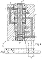
- FIG. 7 shows a sectional view of a valve 1 according to the invention with the housing 9, the cartridge 10 arranged therein and the plunger 11 arranged in the cartridge. Attached thereto is the electromagnetic structure 19 with its corresponding mechanical connecting elements 20.
- FIGS. 8 and 9 each show a side view of the valve 1 according to FIG. 7 with the housing 9 visible from the outside, the electromagnetic structure 19 and its mechanical connecting elements 20.
- FIG. 10 shows a bottom view of the valve 1 according to FIG. 7.
- the housing 9 can be seen in a rectangular plan view, centrally in its center the connection F of the working connection 3 and upwards a part of the electromagnetic structure 19.
Abstract
Description
Die vorliegende Erfindung betrifft ein Ventil für Fluidsysteme nach dem Oberbegriff des Anspruchs 1. Ein Ventil nach dem Oberbegriff des Anspruchs 1 ist z.B. aus DE-A-196 33 191 bekannt.The present invention relates to a valve for fluid systems according to the preamble of
Fluidsteuerungen und/oder Fluidregelungen benötigen für die Realisierung ihrer Funktionen entsprechende Stellelemente. Solche Stellelemente sind beispielsweise Regel- oder Schaltventile.Fluid controls and / or fluid controls require appropriate actuators for the realization of their functions. Such control elements are, for example, control or switching valves.
Insbesondere bei Hydrauliksteuerungen und/oder -regelungen wird das Medium für die Ansteuerung der Aktoren, wie z.B. Zylinder oder Motoren mit hohem Druck beaufschlagt. So können beispielsweise Pumpen eingesetzt werden, die für den Vorsteuerölstrom einen Druck von 30 bar und eine Förderleistung von 10 1 pro Minute erreichen, und für den Hauptölstrom einen Druck von 300 bar und eine Förderleistung von 100 1 pro Minute.In particular, in hydraulic controls and / or controls, the medium is used to drive the actuators, e.g. Cylinder or engines subjected to high pressure. For example, pumps can be used, which achieve a pressure of 30 bar and a flow rate of 10 1 per minute for the pilot oil flow, and for the main oil flow, a pressure of 300 bar and a capacity of 100 1 per minute.
Wenn die Stellelemente in solchen Druckbereichen betrieben werden kann es vorkommen, dass ein Teil des Ölstromes, welcher von den Versorgungsanschlüssen zu ersten Arbeitsanschlüssen durchgeschaltet ist, auch zu zweiten, nicht durchgeschalteten Arbeitsanschlüssen durchdrückt, und den daran angeschlossenen Aktor mit Druck beaufschlagt, obwohl dieser sich im nicht betätigten Zustand befindet. Dabei kann es insbesondere vorkommen, dass lediglich eine Leitung eines Paares von Arbeitsanschlüssen (Zuflussleitung und Rückflussleitung) mit Lecköl beaufschlagt wird. Die Aktoren erfahren also eine einseitige Druckbelastung über die Zu- oder Rückflussleitung des Hydrauliköls, je nachdem, welcher der beiden Anschlüsse mit Lecköl und dessen Druck beaufschlagt wird.If the actuators are operated in such pressure ranges, it may happen that a portion of the oil flow, which is switched from the supply ports to first working ports, also to second, non-switched working ports, and the actuator connected to it pressurized, although this is in the non-actuated state. It may happen in particular that only one line of a pair of working connections (inflow and return line) is acted upon by leak oil. The actuators thus experience a one-sided pressure load on the supply or return line of the hydraulic oil, depending on which of the two ports with leakage oil and its pressure is applied.
Dadurch ergeben sich im Wesentlichen zwei Nachteile. Der ersten Nachteil liegt darin, dass der betroffene Aktor eine Arbeitbewegung ausführt, die nicht gewünscht ist und somit ein entsprechendes Schadens- und Gefahrenspotential mit sich bringt.This essentially results in two disadvantages. The first disadvantage is that the affected actuator performs a work movement that is not desired and thus brings with it a corresponding potential for harm and danger.
Als zweiter Nachteil entsteht die Problematik, dass die Aktoren für eine solche einseitige Druckbeaufschlagung nicht ausgelegt sind. D.h. die mechanischen Bauteile werden über ihre zulässigen Grenzwerte hinaus mit Druck belastet, so dass dadurch Schäden an ihnen entstehen können. So kann beispielsweise bei einem doppelt wirkenden Zylinder das Zylindergehäuse durch den zu hohen Druck beschädigt werden. Entsprechende Schäden können selbstverständlich auch bei Hydraulikmotoren und anderen Komponenten des Hydrauliksystems auftreten.The second disadvantage is the problem that the actuators are not designed for such a one-sided pressurization. That The mechanical components are subjected to pressure beyond their permissible limits, which can cause damage to them. For example, in a double-acting cylinder, the cylinder housing may be damaged by the excessive pressure. Corresponding damage can of course also occur in hydraulic motors and other components of the hydraulic system.
Als Folgeerscheinungen treten Leckagen auf, die einen sehr raschen Austritt des Hydrauliköles aus dem System bewirken können, mit allen entsprechenden Problemen, wie beispielsweise die Gefahr der Verletzung von Personen im entsprechenden Umkreis, die Ölverschmutzung des betroffenen Umfeldes mit den damit einhergehenden zusätzlichen Auswirkungen, der Ausfall des Gerätes selbst, die Reparaturund Instandsetzungskosten und dergleichen mehr.As a consequence, leaks occur, which can cause a very rapid escape of the hydraulic oil from the system, with all the corresponding problems, such as the risk of injury to persons in the appropriate radius, the oil pollution of the affected environment with the associated additional effects, the failure of the device itself, the repair and maintenance costs and the like.
Die Aufgabe der vorliegenden Erfindung ist es deshalb, ein Ventil für Fluidsysteme so weiterzubilden, dass die oben dargelegten Nachteile minimiert oder sogar eliminiert werden.The object of the present invention is therefore to develop a valve for fluid systems in such a way that the disadvantages set out above are minimized or even eliminated.
Diese Aufgabe wird ausgehend von einem handelsüblichen Hydraulikventil nach der einleitend genannten Art durch die kennzeichnenden Merkmale des Anspruchs 1 gelöst. Durch die in den Unteransprüchen genannten Maßnahmen sind vorteilhafte Ausführungsformen und Weiterbildungen der Erfindung möglich.This object is achieved on the basis of a commercially available hydraulic valve according to the introductory type by the characterizing features of
Dementsprechend zeichnet sich ein erfindungsgemäßes Ventil für Fluidsysteme, insbesondere für Hydrauliksysteme, mit zwei ersten Arbeitsanschlüssen C, D für den Zu- und Abfluss des Fluides zu einer ersten, fluidbetätigbaren Vorrichtung und zwei zweiten Arbeitsanschlüssen E, F für den Zu- und Abfluss des Fluides zu einer zweiten fluidbetätigbaren Vorrichtung, und zwei Versorgungsanschlüssen A, B für den versorugungsseitigen Zu- und Abfluss des Fluides dadurch aus, das eine fluidleitende Kurzschluss-Verbindung zwischen den in der jeweiligen Schaltstellung nicht mit den Versorgungsanschlüssen A, B verbundenen Arbeitsanschlüssen C, D bzw. E, F vorhanden ist.Accordingly, an inventive valve for fluid systems, in particular for hydraulic systems, with two first working ports C, D for the inflow and outflow of the fluid to a first, fluid-actuated device and two second working ports E, F for the inflow and outflow of the fluid a second fluid-actuated device, and two supply ports A, B for the supply-side inflow and outflow of the fluid characterized, the a fluid-conducting short-circuit connection between the not connected in the respective switching position with the supply ports A, B working ports C, D and E, , F is present.
Durch die Ausbildung einer Kurzschluss-Verbindung zwischen den in der jeweiligen Schaltstellung nicht mit den Versorgungsanschlüssen A, B verbundenen Arbeitsanschlüssen C, D bzw. E, F wird gewährleistet, dass bei Einbruch von Lecköl in einen der beiden, nicht durchgeschalteten Arbeitsanschlüsse E, F bzw. C, D sichergestellt ist, dass beide Arbeitsanschlüsse, also sowohl die Zuleitung als auch die Rückleitung zu dem jeweiligen Aktor mit dem gleichen Öldruck beaufschlagt werden. Dadurch wird eine einseitige Belastung des betroffenen Aktors vermieden, wodurch die eingangs beschriebenen Nachteile, die sich nach dem bisher bekannten Stand der Technik ergeben können, zumindest minimiert, im optimalen Fall sogar vollständig eliminiert werden.By forming a short-circuit connection between the working connections C, D or E, F which are not connected to the supply connections A, B in the respective switching position, it is ensured that in the event of break-in of leakage oil in one of the two non-switched working connections E, F or C, D it is ensured that both working connections, ie both the supply line and the return line to the respective actuator are subjected to the same oil pressure. As a result, a one-sided load of the actuator concerned is avoided, whereby the disadvantages described above, which may arise according to the previously known prior art, at least minimized, in the optimal case even completely eliminated become.
In einer bevorzugten Ausführungsform kann es vorgesehen sein, dass eine mit fluidleitenden Verbindungselementen versehene, für den Einsatz in einem Gehäuse geeignete Ventilpatrone vorhanden ist. Der Vorteil einer solchen Ausführungsform kann beispielsweise darin liegen, dass eine solche Patrone jederzeit gegen eine andere Patrone ersetzt werden kann, ohne dass es erforderlich ist, das gesamte Ventil auszutauschen. Der Grund für den Wechsel der Ventilpatrone kann dabei vielfältiger Art sein. Sei es, dass die Ventilpatrone selbst, oder Verschleißerscheinungen unterliegende Komponenten der Ventilpatrone nicht mehr einwandfrei funktionieren, oder dass eine geänderte Funktion des Ventiles gewünscht wird. Die Ursache für den Änderungswunsch ist sekundär, wesentlich ist, dass durch ein einfaches Ersetzen der Ventilpatrone innerhalb kürzester Zeit das Ventil in der gewünschten Funktionsweise wieder zur Verfügung steht.In a preferred embodiment it can be provided that a valve cartridge provided with fluid-conducting connection elements and suitable for use in a housing is present. The advantage of such an embodiment may be, for example, that such a cartridge can be replaced at any time with another cartridge without the need to replace the entire valve. The reason for the change of the valve cartridge can be diverse nature. Whether it is the valve cartridge itself or components of the valve cartridge that are subject to wear and tear no longer functioning properly, or that a modified function of the valve is desired. The reason for the change request is secondary, it is essential that by simply replacing the valve cartridge in the shortest possible time the valve is available again in the desired mode of operation.
In einer weiteren Ausführungsform kann es beispielsweise vorgesehen sein, dass ein mit fluidleitenden Verbindungselementen versehenes Gehäuse mit einer Aufnahme für die Ventilpatrone versehen ist. In ein solches Gehäuse können vorteilhafterweise Ventilpatronen in unterschiedlichen Ausführungsformen eingesetzt werden, so dass dadurch gegebenenfalls anwendungsabhängig geänderte Funktionen realisierbar sind.In a further embodiment, it can be provided, for example, that a housing provided with fluid-conducting connecting elements is provided with a receptacle for the valve cartridge. Valve cartridges in different embodiments can advantageously be used in such a housing, so that, if necessary, application-dependent changed functions can be realized.
In einer nächsten Ausführungsform kann es vorgesehen sein, dass die Ventilpatrone einen verschiebbaren Stößel umfasst. Dadurch ergibt sich beispielsweise eine sehr kompakte Bauweise für ein solches Ventil.In a next embodiment it can be provided that the valve cartridge comprises a displaceable plunger. This results, for example, a very compact design for such a valve.
In einer speziellen Ausführungsform kann es dabei vorgesehen sein, dass der Stößel mit fluidleitenden Verbindungselementen versehen ist. Diese Verbindungselemente können z.B.In a specific embodiment, it may be provided that the plunger is provided with fluid-conducting connecting elements. These fasteners can eg
Bohrungen, Ringnuten, Einstiche und dergleichen mehr sein. Durch Verschieben des Stößels in der Patrone können beispielsweise Schalt- und/oder Regelfunktionen realisiert werden. Durch die Ausbildung dieser fluidleitenden Verbindungselemente in oder an dem Stößel kann beispielsweise eine weitere Minimierung an Raumbedarf und/oder eine einfache Herstellung des Ventiles erreicht werden.Holes, grooves, punctures and the like may be more. By shifting the plunger in the cartridge, for example, switching and / or control functions can be realized. By forming these fluid-conducting connecting elements in or on the plunger, for example, a further minimization of space requirements and / or a simple manufacture of the valve can be achieved.
In einer weiteren Ausführungsform kann es vorgesehen sein, dass wenigstens ein Teil der Kurzschluss-Verbindung für die Arbeitsanschlüsse C, D bzw. E, F im Gehäuse für die Aufnahme der Ventilpatrone angeordnet ist. Dadurch ist gewährleistet, dass eine einseitige Belastung bei Einbruch von Lecköl zu einem der beiden Anschlüsse C, D bzw. E, F in den nicht durchgeschalteten Arbeitsanschluss verhindert wird. Diese Ausführungsform kann somit unabhängig von der einzusetzenden Ventilpatrone immer mit einer fluidleitenden Kurzschluss-Verbindung zwischen den jeweiligen Arbeitsanschlüssen E und F bzw. C und D versehen sein.In a further embodiment it can be provided that at least part of the short-circuit connection for the working connections C, D or E, F is arranged in the housing for receiving the valve cartridge. This ensures that a one-sided load is prevented in case of break-in of leakage oil to one of the two ports C, D or E, F in the non-connected working port. This embodiment can thus always be provided with a fluid-conducting short-circuit connection between the respective working ports E and F or C and D, regardless of the valve cartridge to be used.
In einer weiteren Ausführungsform kann es vorgesehen sein, dass wenigstens ein Teil der Kurzschluss-Verbindung für die Arbeitsanschlüsse C und D bzw. E und F in der Ventilpatrone angeordnet ist. Somit kann gegebenenfalls ein einfach aufgebautes Gehäuse durch Ersetzen der Patrone mit dieser Sicherheitsfunktion erweitert werden.In a further embodiment it can be provided that at least part of the short-circuit connection for the working connections C and D or E and F is arranged in the valve cartridge. Thus, if necessary, a simply constructed housing can be expanded by replacing the cartridge with this safety function.
In einer überdies vorteilhaften Ausführungsform kann es vorgesehen sein, dass wenigstens ein Teil der Kurzschluss-Verbindung für die Arbeitsanschlüsse C und D bzw. E und F im Stößel angeordnet ist. Hierdurch kann beispielsweise die Funktion einer gegebenenfalls einfach aufgebauten Patrone erweitert werden.In a further advantageous embodiment, it may be provided that at least a part of the short-circuit connection for the working ports C and D or E and F is arranged in the plunger. As a result, for example, the function of an optionally simply constructed cartridge can be extended.
Grundsätzlich ist es selbstverständlich auch möglich, dass die Kurzschluss-Verbindung über zwei oder auch alle drei beschriebenen Elemente, Gehäuse, Patrone und Stößel ausgebildet ist. Dadurch kann beispielsweise eine vorteilhafte Führung des Ölstromes und/oder eine kompaktere oder einfachere Bauweise für das Ventil erreicht werden.In principle, it is of course also possible that the short-circuit connection over two or all three described elements, housing, cartridge and plunger is formed. As a result, for example, an advantageous guidance of the oil flow and / or a more compact or simpler design for the valve can be achieved.
In einer bevorzugten Ausführungsform kann es vorgesehen sein, dass das Ventil als 6/2-Wegeventil ausgebildet ist. Ein solches 6/2-Wegeventil weist den Vorteil auf, dass es im Steuer- bzw. Regelfall direkt von einer Arbeitseinheit oder deren Bewegungsrichtung auf die andere Arbeitseinheit oder deren Bewegungsrichtung umschalten kann, wobei sehr geringe Verzögerungszeiten zwischen den beiden Schaltzuständen erreicht werden können.In a preferred embodiment, it can be provided that the valve is designed as a 6/2-way valve. Such a 6/2-way valve has the advantage that, in the control or regulating case, it can switch directly from one working unit or its direction of movement to the other working unit or its direction of movement, wherein very short delay times between the two switching states can be achieved.
In einer demgegenüber abgewandelten Ausführungsform kann es vorgesehen sein, dass das Ventil als 6/3-Wegeventil ausgebildet ist. Ein solches 6/3-Wegeventil hat den Vorteil, dass die ersten durchgeschalteten Arbeitsanschlüsse länger von den Versorgungsanschlüssen getrennt und damit abgeschaltet sind, bis die zweiten durchzuschaltenden Arbeitsanschlüsse fluidleitend durchgeschaltet sind, als dies beispielsweise bei der demgegenüber schneller schaltenden 6/2-Wegeventil-Ausführungsform der Fall ist. Durch einen solchen Aufbau kann beispielsweise eine zusätzliche Sicherheitsreserve dahingehend erzielt werden, dass die zuvor angesteuerte Vorrichtung oder deren Bewegung auf alle Fälle zum Stillstand kommt, bevor die nächste Vorrichtung oder deren Bewegung aktiviert wird.In a modified embodiment on the other hand, it may be provided that the valve is designed as a 6/3-way valve. Such a 6/3-way valve has the advantage that the first through-connected working ports longer disconnected from the supply ports and thus are turned off until the second durchzuschaltenden working ports are fluidly switched through, as for example in the contrast faster switching 6/2-way valve embodiment the case is. By such a structure, for example, an additional safety margin can be achieved in that the previously controlled device or its movement comes to a standstill in any case, before the next device or its movement is activated.
In einer nächsten Ausführungsform kann es vorgesehen sein, dass eine neutrale Schaltstellung für das Ventil ausgebildet ist, in der weder die ersten Arbeitsanschlüsse E, F noch die zweiten Arbeitsanschlüsse C, D mit den Versorgungsanschlüssen A, B durchgeschaltet sind.In a next embodiment it can be provided that a neutral switching position is formed for the valve, in which neither the first working ports E, F nor the second working ports C, D are connected to the supply ports A, B.
Diese'Ausführungsform bietet den Vorteil, dass sie in einen Zustand versetzt werden kann, in dem keiner der Arbeitsanschlüsse fluidleitend durchgeschaltet ist. Dazu sind wahlweise unterschiedliche Ausführungsformen denkbar. In einer ersten, einfachen Ausführungsform kann es vorgesehen sein, dass in dieser Schaltstellung alle Anschlüsse, also die beiden ersten und zweiten Arbeitsanschlüsse C, D bzw. E, F sowie auch die Versorgungsanschlüsse A, B allesamt lediglich einzeln für sich geschlossen sind.This embodiment offers the advantage of being in one Condition can be offset in which none of the working ports is fluid-conducting switched through. For this purpose, different embodiments are conceivable. In a first, simple embodiment, it may be provided that in this switching position, all connections, that is to say the two first and second working connections C, D or E, F as well as the supply connections A, B, are all closed only individually.
In einer demgegenüber abgewandelten Ausführungsform ist es beispielsweise vorstellbar, dass wenigstens die ersten oder zweiten Arbeitsanschlüsse C und D bzw. E und F in dieser Schaltstellung eine Kurschluss-Verbindung aufweisen. In einer demgegenüber bevorzugten Ausführungsform ist es aber auch möglich, dass sowohl für beide Arbeitsanschlüsse C und D bzw. E und F als auch für die Versorgungsanschlüsse A und B eine Kurschluss-Verbindung in dieser Schaltstellung ausgebildet ist.In a modified embodiment on the other hand, it is conceivable, for example, that at least the first or second working connections C and D or E and F have a short-circuit connection in this switching position. In contrast, in a preferred embodiment, it is also possible that both for both working ports C and D and E and F and for the supply terminals A and B, a short-circuit connection is formed in this switching position.
In einer weiteren Ausführungsform kann es vorgesehen sein, dass für die Betätigung des Ventiles eine Magnetspule vorhanden ist. Durch die Anordnung einer Magnetspule, die beispielweise gegen eine Feder arbeitet, ist es möglich, das Ventil elektrisch gegen die Kraft der Feder zu verstellen.In a further embodiment it may be provided that a solenoid is provided for the actuation of the valve. By arranging a magnetic coil, for example, working against a spring, it is possible to electrically adjust the valve against the force of the spring.
In einer demgegenüber bevorzugten Ausführungsform kann es vorgesehen sein, dass die Magnetspule als Zweiwege-Magnetspule ausgebildet ist. Dadurch kann beispielsweise ein 6/3-Wegeventil realisiert werden, welches mittels Federkraft in der Neutralstellung gehalten wird und je nach Ansteuerung der Magnetspule die ersten bzw. zweiten Arbeitsanschlüsse C, D bzw. E, F mit den Versorgungsanschlüssen A, B fluidleitend durchschaltet.In a contrast preferred embodiment, it may be provided that the magnetic coil is designed as a two-way magnetic coil. As a result, for example, a 6/3-way valve can be realized, which is held by spring force in the neutral position and depending on the control of the solenoid coil, the first and second working ports C, D and E, F with the supply ports A, B fluidly conductive.
In einer weiteren Ausführungsform kann es vorgesehen sein, dass für die Rückstellung des Ventils eine Feder vorhanden ist. Diese Feder kann beispielsweise die Rückstellung des Ventiles bewirken, wenn das Ventil entweder, wie oben beschrieben über eine Magnetspule aktiviert wird, oder wenn sie beispielsweise über ein Fluid verstellt wird. Vorzugsweise ist das Fluid dann ebenfalls ein Hydrauliköl, es ist aber durchaus auch möglich, ein gasförmiges Medium für die Ansteuerung vorzusehen. Selbstverständlich können aber auch eine Nockensteuerung, eine Handbetätigung und dergleichen mehr für die Aktivierung des Ventils vorgesehen sein. Die Feder bewirkt die Rückstellung, sobald die auf das Ventil wirkende Stellkraft kleiner als die Federkraft ist.In a further embodiment it can be provided that a spring is provided for the return of the valve is. This spring can for example cause the return of the valve when the valve is either activated as described above via a magnetic coil, or if it is adjusted for example via a fluid. Preferably, the fluid is then also a hydraulic oil, but it is also quite possible to provide a gaseous medium for the control. Of course, but also a cam control, a manual operation and the like may be provided for the activation of the valve. The spring causes the return as soon as the force acting on the valve actuating force is smaller than the spring force.
In einer besonderen Ausführungsform kann es vorgesehen sein, dass das Ventil als Teil eines mit mehreren Ventilen verbindbaren Ventilblocks ausgebildet ist. In einer solchen Ausführungsform kann es beispielsweise vorgesehen sein, dass einzelne Ventile oder auch Ventilgruppen zu einer größeren Schalt- und/oder Regeleinheit zusammengeschaltet sind. Dadurch ist die Realisierung von Schalt- und/oder Regelkreisen in Blockform möglich. Gegebenenfalls können solche Blöcke wiederum entsprechend ihrer Funktionen sinnvoll weiter zusammen in eine Steuerung und/oder Regelung eingebaut werden.In a particular embodiment, it can be provided that the valve is designed as part of a valve block which can be connected to a plurality of valves. In such an embodiment, it can be provided, for example, that individual valves or valve groups are interconnected to form a larger switching and / or control unit. As a result, the realization of switching and / or control circuits in block form is possible. If appropriate, such blocks can in turn, according to their functions, be usefully further integrated together in a control and / or regulation.
Anhand der beigefügten Zeichnungen werden nachfolgend verschiedene Ausführungsbeispiele des erfindungsgemäßen Ventils für Fluidsysteme näher beschrieben. Es zeigen:
Figur 1- Das Schaltbildsymbol eines erfindungsgemäßen 6/2-Wegeventils,
Figuren 2 bis 4- die
Schaltbildsymbole eines 6/3-Wegeventiles, jeweils zusammen mit einem möglichen Ausführungsbeispiel anhand dargestellter leitender und nicht leitender Schaltverbindungen, Figur 5- ein Schaltbildsymbol für eine weitere Ausführungsform eines erfindungsgemäßen 6/3-Wegeventiles,
Figur 6- einen beispielhaften Schaltplan, in dem ein erfindungsgemäßes 6/2-Wegeventil im Stromkreis des Vorsteuerölstroms angeordnet ist,
Figur 7- einen Schnitt durch einen beispielhaften Aufbau eines erfindungsgemäßen Ventiles,
Figuren 8 und 9- jeweilige Seitenansichten zu einem Ventil entsprechend der Figur 7 und
Figur 10- eine Unteransicht auf das
Ventil nach Figur 7.
- FIG. 1
- The circuit diagram of a 6/2-way valve according to the invention,
- FIGS. 2 to 4
- the circuit diagram symbols of a 6/3-way valve, each together with a possible embodiment illustrated by conductive and not conductive switching connections,
- FIG. 5
- a circuit diagram symbol for a further embodiment of a 6/3-way valve according to the invention,
- FIG. 6
- an exemplary circuit diagram in which a 6/2-way valve according to the invention is arranged in the circuit of the pilot oil flow,
- FIG. 7
- a section through an exemplary construction of a valve according to the invention,
- FIGS. 8 and 9
- respective side views of a valve according to the figure 7 and
- FIG. 10
- a bottom view of the valve of Figure 7.
Figur 1 zeigt ein Schaltbildsymbol für ein 6/2-Wegeventil in der erfindungsgemäßen Ausführungsform. Dazu sind im linken Schaltblock die Anschlüsse C und D des Arbeitsanschlusses 2 und im rechten Schaltblock die Anschlüsse E und F des Arbeitanschlusses 3 mit Kurzschluss-Verbindungen 5 versehen. Diese Kurzschluss-Verbindungen stellen sicher, dass bei Einbruch eines Leckölstroms an einen der beiden Anschlüsse C oder D bzw. E oder F des jeweils nicht durchgeschalteten Arbeitsanschlusses zwingend auch der zweite Anschluss mit dem gleichen Öldruck beaufschlagt wird. Dadurch wird erreicht, dass sowohl die Zuleitung als auch die Rückleitung des betroffenen Arbeitsanschlusses mit dem gleichen Öldruck beaufschlagt werden. Als Betätigungsorgane sind eine Spule 7 und eine Feder 8 symbolisch dargestellt.FIG. 1 shows a circuit diagram symbol for a 6/2-way valve in the embodiment according to the invention. For this purpose, the connections C and D of the working
Je nach dem, welche Schaltstellung betrachtet wird, die linke oder die rechte in der dargestellten Ausführungsform, ist die Durchschaltung des von der Pumpe geförderten Ölstroms über den Versorgungsanschluss A zum Arbeitsanschluss E bzw. C und die Rückleitung über den Arbeitsanschluss F bzw. D an den Tankanschluss B realisiert.Depending on which switching position is considered, the left or the right in the illustrated embodiment, the switching of the pumped by the pump oil flow through the supply port A to the working port E or C and the return line via the working port F and D to the Tank connection B realized.
Aufgrund der Tatsache, dass die mechanischen Bauteile einerseits gewisse Toleranzen bei der Fertigung aufweisen, und andererseits solche auch benötigen, um funktionstüchtig zu sein, kann bei hohen Öldrücken aus einer dieser beschriebenen Verbindungen A-E, F-B Lecköl an einer entsprechenden Stelle an einen der Anschlüsse C oder D des anderen Arbeitsanschlusses durchsickern. Die Kurzschluss-Verbindung 5 zwischen den Anschlüssen C und D sorgt in diesem Fall für den entsprechenden Druckausgleich zwischen diesen beiden Anschlüssen C und D. Das Gleiche gilt im entsprechenden Fall für die rechte Schaltstellung, bei der der Arbeitsanschluss 2 mit dem Versorgungsanschluss 4 durchgeschaltet ist. In diesem Fall ist der Arbeitsanschluss 3 nicht durchgeschaltet und das Ventil weist in dieser Stellung eine Kurzschluss-Verbindung 5 für die Anschlüsse E und F auf, um ebenfalls sicherzustellen, dass an beiden Anschlüssen E und F bei Einbruch eines Leckölstroms der gleiche Druck vorherrscht.Due to the fact that the mechanical components on the one hand have certain manufacturing tolerances, and on the other hand require such to be functional, at high oil pressures from one of these described connections AE, FB leakage oil at a corresponding location to one of the terminals C or D leakage from the other work connection. The short-
Die Figur 2 zeigt ein Schaltbildsymbol für ein erfindungsgemäßes 6/3-Wegeventil sowie eine Darstellung von fluidleitenden Verbindungen in einem Ventil entsprechend der gezeigten Schaltstellung aus dem Schaltplansymbol. Im linken Symbolblock des Schaltplansymbols ist der Arbeitsanschluss 3 für das Ventil 1 über die Schaltverbindungen 6 mit dem Versorgungsanschluss 4 verbunden. Für den Arbeitsanschluss 2 ist zwischen den Anschlüssen C und D die Kurzschluss-Verbindung 5 ausgebildet.2 shows a circuit diagram symbol for a 6/3-way valve according to the invention and a representation of fluid-conducting connections in a valve according to the switching position shown in the circuit diagram symbol. In the left-hand symbol block of the circuit diagram symbol, the working
Im mittleren Symbolblock sind alle Anschlüsse A bis F im verschlossenen Zustand dargestellt. Hierbei handelt es sich um die Neutralstellung des 6/3-Wegeventils. Im rechten Symbolblock ist die komplementäre Schaltverbindung für die Durchschaltung des Arbeitsanschlusses 2 mit dem Versorgungsanschluss 4 gezeigt. In dieser Schaltstellung ist für den Arbeitsanschluss 3 zwischen den Anschlüssen E und F eine Kurzschluss-Verbindung 5 vorgesehen. Details zur neutralen Schaltstellung und zur Schaltung, in der der Arbeitsanschluss 2 mit dem Versorgungsanschluss 4 verbunden ist, finden sich in den Erläuterungen zu den Figuren 3 und 4.In the middle symbol block all connections A to F are shown in the closed state. This is the neutral position of the 6/3-way valve. In the right-hand block of symbols, the complementary switching connection for the connection of the working
Die über dem Schaltsymbol beispielhaft dargestellten fluidleitenden Verbindungen symbolisieren den teilweisen Aufbau eines erfindungsgemäßen Ventils mit einem Gehäuse 9 in welchem eine Patrone 10 angeordnet ist. In diesem Gehäuse 9 ist ein Teil der Kurzschluss-Verbindung 5 zwischen dem Anschluss C und dem Anschluss D ausgebildet. Ein weiterer Teil dieser Kurzschluss-Verbindung 5 zwischen den Anschlüssen C und D des Arbeitsanschlusses 2 ist in der Patrone 10 ausgebildet. Dieser Teil der Kurzschluss-Verbindung 5 ist zum Teil als Einstich in die Außenkontur der Patrone und zum Teil als Bohrung ausgebildet.The fluid-conducting connections exemplified above the switching symbol symbolize the partial construction of a valve according to the invention with a
Im Inneren der Patrone 10 ist ein Stößel 11 angeordnet. Dieser Stößel 11 weist ebenfalls Teile der Kurzschluss-Verbindung 5 auf, die zwischen dem Anschluss C und dem Anschluss D in dieser Schaltstellung des Ventils 1 realisiert ist.Inside the
Die Schaltverbindung 6 zwischen dem Anschluss A des Versorgungsanschlusses 4 und dem Anschluss E des Arbeitsanschlusses 3 ist ebenfalls über alle drei Einheiten, Gehäuse 9, Patrone 10 und Stößel 11 verteilt ausgebildet. Die zweite Schaltverbindung 6 vom Tankanschluss, also dem Anschluss B des Versorgungsanschlusses 4 zum Anschluss F des Arbeitsanschlusses 3, ist ebenfalls über alle drei Einheiten, Gehäuse 9, Patrone 10 und Stößel 11, ausgebildet.The
Der Stößel weist in dieser Ausführungsform eine axial ausgebildete, durchgehende Bohrung auf, die stirnseitig mit dem Anschluss F verbunden ist. Mit dieser verbunden sind zwei axial voneinander beabstandete, radial ausgerichtete Kreuzbohrungen, die je nach Schaltstellung Teil der Schaltverbindung 6 bzw. der Kurschluss-Verbindung 5 sind.In this embodiment, the plunger has an axially formed, continuous bore which is connected to the terminal F at the end face. Connected to this are two axially spaced, radially aligned cross bores, which are part of the
Die Figur 3 zeigt wiederum das Schaltplansymbol für das Ventil 1 und darüber angeordnet die fluidleitenden Verbindungen in einem beispielhaft dargestellten Ventil mit Ventilpatrone 10 und darin angeordnetem Stößel 11. In dieser Ansicht ist der Stößel gegenüber der Ansicht in der Figur 2 axial nach unten verschoben, so dass keine Verbindungen zwischen den einzelnen Anschlüssen der Arbeits- und Versorgungsanschlüsse 2 bis 4 mehr bestehen. Das heißt, es ist also weder einer der Arbeitsanschlüsse 2, 3 mit dem Versorgungsanschluss 4 über Schaltverbindungen 6 verbunden, noch bestehen Kurzschluss-Verbindungen 5 zwischen den einzelnen Anschlüssen C und D bzw. E und F der Arbeitsanschlüsse. Im Schaltplansymbol wird das durch die entsprechenden Leitungsabschlüsse im mittleren Schaltblock dargestellt.FIG. 3 again shows the circuit diagram symbol for the
In der Darstellung der fluidleitenden Verbindungen in der Ausführungsform des Ventils 1 ist dies durch die verschobene Position des Stößels 11 entlang seiner Achse im Inneren der Patrone 10 realisiert. Die Patrone 10 ist dabei unverändert im Gehäuse 9 angeordnet.In the illustration of the fluid-conducting connections in the embodiment of the
Die Darstellung der Figur 4 ist die komplementäre Schaltdarstellung zur Darstellung in Figur 2. Dies gilt sowohl für das Schaltplansymbol als auch für die Darstellung der fluidleitenden Verbindungen in dem Ausführungsbeispiel des Ventils 1. Im Schaltplansymbol ist der rechte der drei Symbolblöcke mit den beiden Arbeitsanschlüssen 2, 3 und dem Versorgungsanschluss 4 verbunden. Dieser Schaltzustand spiegelt sich selbstverständlich im darüber gezeigten Ausführungsbeispiel wieder. Durch weiteres Verschieben des Stößels 11 in axialer Richtung nach unten hin gegenüber den Darstellungen in den Figuren 2 und 3 sind die Verbindungen A-C und D-B mittels der Schaltverbindung 6 durchgeschaltet. Diese Verbindungen sind ebenfalls wiederum über alle drei Elemente des Ventils 1, also dem Gehäuse 9, der Patrone 10 und dem Stößel 11 ausgebildet. Die Kurzschluss-Verbindung ist entsprechend zwischen den Anschlüssen E und F dargestellt.The illustration of FIG. 4 is the complementary circuit diagram for illustration in FIG. 2. This applies both to the circuit diagram symbol and to the representation In the schematic diagram, the right of the three symbol blocks with the two working
Die Figur 5 zeigt ein weiteres Schaltplansymbol für eine mögliche Ausführungsform eines 6/3-Wegeventils. In dieser Darstellung sind die Anschlüsse C und D des Arbeitsanschlusses 2 und die Anschlüsse E und F des Arbeitsanschlusses 3 im neutralen Schaltzustand des Ventils 1 jeweils durch Kurzschluss-Verbindungen 5 miteinander verbunden. Die Anschlüsse A und B des Versorgungsanschlusses 4 sind voneinander getrennt verschlossen dargestellt.FIG. 5 shows a further circuit diagram symbol for a possible embodiment of a 6/3-way valve. In this illustration, the terminals C and D of the working
In der Figur 6 ist eine beispielhafte Darstellung eines Hydraulikschaltplanes mit Vorsteuer- und Hauptölstromkreis gezeigt, bei der ein erfindungsgemäßes Ventil für Fluidsysteme in der Form eines 6/2-Wegeventils eingesetzt ist. Das Ventil 1 liegt im Vorsteuerölstromkreis und betätigt, je nach Schaltstellung eines der beiden Hauptsteuerventile 13 bzw. 14 im Hauptölstromkreis. Der Vorsteuerölstrom wird von der Pumpe der Ölversorgung 17 erzeugt. In diesem Schaltkreis herrscht beispielsweise ein Druck von 30 bar bei einer Förderleistung von 10 1 pro Minute. Damit werden die Hauptsteuerventile 13 bzw. 14 für die beiden Arbeitszylinder 15 bzw. 16 angesteuert. Im Hauptölstrom herrscht beispielsweise ein Druck von 300 bar bei einer Versorgungsleistung von 100 1 pro Minute. Versorgt werden die beiden Hauptölstromkreise aus den jeweiligen Ölversorgungen 18.FIG. 6 shows an exemplary representation of a hydraulic circuit diagram with pilot oil and main oil circuit, in which a valve according to the invention for fluid systems in the form of a 6/2-way valve is used. The
Je nachdem, in welcher Schaltstellung sich nun das 6/2-Wegeventil befindet, wird entweder das Hauptsteuerventil 13 oder das Hauptsteuerventil 14 über den entsprechenden Arbeitsanschluss 2 bzw. 3 angesteuert. Der jeweils andere Arbeitsanschluss 3 bzw. 2 weist dann eine Kurzschluss-Verbindung 5 zwischen seinen beiden Anschlüssen C und D bzw. E und F auf.Depending on the switching position in which the 6/2-way valve is now located, either the
Die Richtung des durchströmenden Öls im Vorsteuerstromkreis wird mittels dem Vorsteuergerät 12 vorgegeben. Je nachdem in welcher Steuerstellung das Vorsteuergerät aktiviert wird, fließt der Vorsteuer-Ölstrom in gerader bzw. in gekreuzter Durchflussrichtung durch das Vorsteuergerät 12 und wirkt entsprechend auf das gleichzeitig durch das Ventil 1 angesteuerte Hauptsteuerventil 13 bzw. 14. Dementsprechend wird der betreffende Arbeitszylinder 15 bzw. 16 durch das jeweilige Hauptsteuerventil 13 bzw. 14 aus- oder einfahrend angesteuert.The direction of the oil flowing through in the pilot control circuit is predetermined by means of the
Die Darstellung der Figur 7 zeigt eine Schnittdarstellung eines erfindungsgemäßen Ventiles 1 mit dem Gehäuse 9, der darin angeordneten Patrone 10 und dem in der Patrone angeordneten Stößel 11. Darauf aufgesetzt ist der elektromagnetische Aufbau 19 mit seinen entsprechenden mechanischen Verbindungselementen 20 dargestellt.7 shows a sectional view of a
Die Figuren 8 und 9 zeigen jeweils eine Seitenansicht des Ventiles 1 nach Figur 7 mit dem von außen sichtbaren Gehäuse 9, dem elektromagnetischen Aufbau 19 und dessen mechanischen Verbindungselementen 20.FIGS. 8 and 9 each show a side view of the
Die Figur 10 zeigt eine Unteransicht des Ventiles 1 nach Figur 7. Dabei ist das Gehäuse 9 im rechteckigen Grundriss erkennbar, zentral in seiner Mitte der Anschluss F des Arbeitsanschlusse 3 und nach oben hin ein Teil des elektromagnetischen Aufbaus 19.FIG. 10 shows a bottom view of the
- 11
- VentilValve
- 22
- Arbeitsanschlussworking port
- 33
- Arbeitsanschlussworking port
- 44
- Versorgungsanschlusssupply terminal
- 55
- Kurzschluss-VerbindungShort link
- 66
- Schaltverbindunginterconnection
- 77
- SpuleKitchen sink
- 88th
- Federfeather
- 99
- Gehäusecasing
- 1010
- Patronecartridge
- 1111
- Stößeltappet
- 1212
- Vorsteuergerätpilot control unit
- 1313
- HauptsteuerventilMain control valve
- 1414
- HauptsteuerventilMain control valve
- 1515
- Arbeitszylinderworking cylinder
- 1616
- Arbeitszylinderworking cylinder
- 1717
- Ölversorgungoil supply
- 1818
- Ölversorgungoil supply
- 1919
- Elektromagnetischer AufbauElectromagnetic structure
- 2020
- Mechanische VerbindungselementeMechanical fasteners
Claims (15)
- Valve (1) for fluid systems, in particular for hydraulic systems, with two first working connections (C, D) for the inflow and outflow of the fluid to a first, fluid-activated device, and two second working connections (E, F) for the inflow and outflow of the fluid to a second fluid-activated device, and two supply connections (A, B) for the supply-side inflow and outflow of the fluid, characterised in that a fluid-guiding short-circuiting connection (5) is provided between the working connections (C and D or E and F) not connected to the supply connections (A, B) in each switch position.
- Valve (1) according to claim 1, characterised in that a valve cartridge (10) is provided that has fluid-guiding connecting elements and is suitable for use in a housing (9).
- Valve (1) according to claim 2, characterised in that a housing (9) provided with fluid-guiding connecting elements is fitted with a mount for the valve cartridge (10).
- Valve (1) according to claim 2 or 3, characterised in that the valve cartridge (10) comprises a displaceable ram (11).
- Valve (1) according to claim 4, characterised in that the ram is provided with fluid-guiding connecting elements.
- Valve (1) according to one of claims 2 to 5, characterised in that at least one part of the short-circuiting connection (5) for the working connections (C, D) or (E, F) is arranged in the housing for mounting the valve cartridge (10).
- Valve (1) according to one of claims 2 to 6, characterised in that at least a part of the short-circuiting connection (5) for the working connections (C, D) or (E, F) is arranged in the valve cartridge (10).
- Valve (1) according to one of claims 4 to 7, characterised in that at least a part of the short-circuiting connection for the working connections (C, D) or (E, F) is arranged in the ram (11).
- Valve (1) according to one of the preceding claims, characterised in that the valve is designed as a 6/2 way valve.
- Valve (1) according to one of claims 1 to 8, characterised in that the valve is designed as a 6/3 way valve.
- Valve (1) according to claim 10, characterised in that a neutral switching position for the valve is formed, in which neither the first working connections (E, F) nor the second working connections (C, D) are connected through to the supply connections (A, B).
- Valve (1) according to one of the preceding claims, characterised in that for the activation of the valve a magnetic coil (7) is provided.
- Valve (1) according to claim 12, characterised in that the magnetic coil (7) is designed as a two-way magnetic coil.
- Valve (1) according to one of the preceding claims, characterised in that a spring (8) is provided for the resetting the valve.
- Valve (1) according to one of the preceding claims, characterised in that the valve is designed as part of a valve block connectable with several valves.
Applications Claiming Priority (2)
| Application Number | Priority Date | Filing Date | Title |
|---|---|---|---|
| DE10349228A DE10349228A1 (en) | 2003-10-23 | 2003-10-23 | Valve for fluid system |
| DE10349228 | 2003-10-23 |
Publications (3)
| Publication Number | Publication Date |
|---|---|
| EP1526289A2 EP1526289A2 (en) | 2005-04-27 |
| EP1526289A3 EP1526289A3 (en) | 2005-07-27 |
| EP1526289B1 true EP1526289B1 (en) | 2006-09-06 |
Family
ID=34384407
Family Applications (1)
| Application Number | Title | Priority Date | Filing Date |
|---|---|---|---|
| EP04022742A Not-in-force EP1526289B1 (en) | 2003-10-23 | 2004-09-24 | Valve for a fluid system |
Country Status (3)
| Country | Link |
|---|---|
| EP (1) | EP1526289B1 (en) |
| AT (1) | ATE338889T1 (en) |
| DE (2) | DE10349228A1 (en) |
Families Citing this family (3)
| Publication number | Priority date | Publication date | Assignee | Title |
|---|---|---|---|---|
| US8464754B2 (en) | 2008-06-02 | 2013-06-18 | Eaton Corporation | Valve manifold |
| US8302627B2 (en) * | 2008-06-02 | 2012-11-06 | Eaton Corporation | Hydraulic system |
| DE102022118889A1 (en) | 2022-07-27 | 2024-02-01 | Liebherr-Aerospace Lindenberg Gmbh | Valve and aircraft |
Family Cites Families (8)
| Publication number | Priority date | Publication date | Assignee | Title |
|---|---|---|---|---|
| BE528346A (en) * | ||||
| US3015344A (en) * | 1958-05-24 | 1962-01-02 | Schlepperwerk Nordhausen Veb | Hydraulic control valve |
| FR1227434A (en) * | 1959-03-06 | 1960-08-19 | Rech Etudes Production Sarl | Device for the remote hydraulic control of independent receivers operating simultaneously |
| DE3110210A1 (en) * | 1981-03-17 | 1982-09-30 | Hartmann & Lämmle GmbH & Co KG, 7255 Rutesheim | Hydraulic operating device for controlling the working and stoppage phases of machines or machine tools |
| DE3639174C2 (en) * | 1986-11-15 | 1998-02-05 | Bosch Gmbh Robert | Hydraulic control device |
| DE19633191C2 (en) * | 1996-08-17 | 1998-07-02 | Daimler Benz Ag | Changeover valve for a pressure medium |
| DE19723219A1 (en) * | 1997-06-03 | 1998-12-10 | Frutigen Hydrotechnik Ag | Hydraulic multi-way valve, in particular steering type selector valve for multi-axle steered vehicles |
| DE10223717A1 (en) * | 2002-05-28 | 2003-12-11 | Linde Ag | Hydrostatic drive system e.g. for excavator, has valve device that can be acted upon in direction of throughflow position connecting first and second sides of load depending on pressures on first and second sides of load |
-
2003
- 2003-10-23 DE DE10349228A patent/DE10349228A1/en not_active Withdrawn
-
2004
- 2004-09-24 DE DE502004001399T patent/DE502004001399D1/en active Active
- 2004-09-24 AT AT04022742T patent/ATE338889T1/en active
- 2004-09-24 EP EP04022742A patent/EP1526289B1/en not_active Not-in-force
Also Published As
| Publication number | Publication date |
|---|---|
| EP1526289A3 (en) | 2005-07-27 |
| DE502004001399D1 (en) | 2006-10-19 |
| DE10349228A1 (en) | 2005-05-19 |
| ATE338889T1 (en) | 2006-09-15 |
| EP1526289A2 (en) | 2005-04-27 |
Similar Documents
| Publication | Publication Date | Title |
|---|---|---|
| EP0850151B1 (en) | Means for roll stabilisation of a vehicle | |
| EP0628731B1 (en) | Pilot-actuated servovalve | |
| EP2488764B1 (en) | Valve system | |
| EP2234135B1 (en) | Valve assembly | |
| DE3347000C2 (en) | ||
| DE19537482A1 (en) | Hydraulic control block | |
| WO2014117922A1 (en) | Motor vehicle transmission device having a hydraulic system | |
| EP0641919B1 (en) | Safety valve arrangement | |
| WO2017125108A1 (en) | Hydraulic switching assembly for a motor vehicle | |
| EP2647883B1 (en) | Hydraulic control device | |
| EP2415059A1 (en) | Hydromechanical drive for electrical circuit breakers | |
| EP1526289B1 (en) | Valve for a fluid system | |
| DE102018124912B4 (en) | Hydraulic steering device with ratio change | |
| EP0628730B1 (en) | Hydraulic system, particularly for a power brake | |
| WO2014056592A1 (en) | Open-centre valve block with two pump connections and associated auxiliary sliders on the main sliders | |
| DE102016216264A1 (en) | Fluid arrangement for actuating vehicle components | |
| EP2171287B1 (en) | Device for adjusting an actuator | |
| EP2163770B1 (en) | Internal load pressure sensing means for a directional control spool valve | |
| DE102009038377A1 (en) | Hydraulic arrangement for controlling clutches of adjustable torque distributor device in motor vehicle, has common supply connected with high pressure circuit behind branch to low pressure circuit by valve closed against pumping direction | |
| DE3817123A1 (en) | SAFETY VALVE | |
| EP2452078B1 (en) | Device for providing a variable restriction for a fluid flow | |
| EP1409325B1 (en) | Hydraulic power-assisted steering system with an integrated construction | |
| DE102013216790A1 (en) | Switching fitting arrangement | |
| EP1203161B1 (en) | Security valve for a press | |
| DE3519148C2 (en) |
Legal Events
| Date | Code | Title | Description |
|---|---|---|---|
| PUAI | Public reference made under article 153(3) epc to a published international application that has entered the european phase |
Free format text: ORIGINAL CODE: 0009012 |
|
| AK | Designated contracting states |
Kind code of ref document: A2 Designated state(s): AT BE BG CH CY CZ DE DK EE ES FI FR GB GR HU IE IT LI LU MC NL PL PT RO SE SI SK TR |
|
| AX | Request for extension of the european patent |
Extension state: AL HR LT LV MK |
|
| PUAL | Search report despatched |
Free format text: ORIGINAL CODE: 0009013 |
|
| AK | Designated contracting states |
Kind code of ref document: A3 Designated state(s): AT BE BG CH CY CZ DE DK EE ES FI FR GB GR HU IE IT LI LU MC NL PL PT RO SE SI SK TR |
|
| AX | Request for extension of the european patent |
Extension state: AL HR LT LV MK |
|
| RIC1 | Information provided on ipc code assigned before grant |
Ipc: 7F 15B 13/06 B Ipc: 7F 15B 13/04 A |
|
| 17P | Request for examination filed |
Effective date: 20051027 |
|
| AKX | Designation fees paid |
Designated state(s): AT BE BG CH CY CZ DE DK EE ES FI FR GB GR HU IE IT LI LU MC NL PL PT RO SE SI SK TR |
|
| GRAP | Despatch of communication of intention to grant a patent |
Free format text: ORIGINAL CODE: EPIDOSNIGR1 |
|
| GRAS | Grant fee paid |
Free format text: ORIGINAL CODE: EPIDOSNIGR3 |
|
| GRAA | (expected) grant |
Free format text: ORIGINAL CODE: 0009210 |
|
| AK | Designated contracting states |
Kind code of ref document: B1 Designated state(s): AT BE BG CH CY CZ DE DK EE ES FI FR GB GR HU IE IT LI LU MC NL PL PT RO SE SI SK TR |
|
| PG25 | Lapsed in a contracting state [announced via postgrant information from national office to epo] |
Ref country code: IE Free format text: LAPSE BECAUSE OF FAILURE TO SUBMIT A TRANSLATION OF THE DESCRIPTION OR TO PAY THE FEE WITHIN THE PRESCRIBED TIME-LIMIT Effective date: 20060906 Ref country code: RO Free format text: LAPSE BECAUSE OF FAILURE TO SUBMIT A TRANSLATION OF THE DESCRIPTION OR TO PAY THE FEE WITHIN THE PRESCRIBED TIME-LIMIT Effective date: 20060906 Ref country code: PL Free format text: LAPSE BECAUSE OF FAILURE TO SUBMIT A TRANSLATION OF THE DESCRIPTION OR TO PAY THE FEE WITHIN THE PRESCRIBED TIME-LIMIT Effective date: 20060906 Ref country code: SI Free format text: LAPSE BECAUSE OF FAILURE TO SUBMIT A TRANSLATION OF THE DESCRIPTION OR TO PAY THE FEE WITHIN THE PRESCRIBED TIME-LIMIT Effective date: 20060906 Ref country code: FI Free format text: LAPSE BECAUSE OF FAILURE TO SUBMIT A TRANSLATION OF THE DESCRIPTION OR TO PAY THE FEE WITHIN THE PRESCRIBED TIME-LIMIT Effective date: 20060906 Ref country code: SK Free format text: LAPSE BECAUSE OF FAILURE TO SUBMIT A TRANSLATION OF THE DESCRIPTION OR TO PAY THE FEE WITHIN THE PRESCRIBED TIME-LIMIT Effective date: 20060906 Ref country code: NL Free format text: LAPSE BECAUSE OF FAILURE TO SUBMIT A TRANSLATION OF THE DESCRIPTION OR TO PAY THE FEE WITHIN THE PRESCRIBED TIME-LIMIT Effective date: 20060906 |
|
| REG | Reference to a national code |
Ref country code: GB Ref legal event code: FG4D Free format text: NOT ENGLISH |
|
| REG | Reference to a national code |
Ref country code: CH Ref legal event code: EP |
|
| PG25 | Lapsed in a contracting state [announced via postgrant information from national office to epo] |
Ref country code: BE Free format text: LAPSE BECAUSE OF NON-PAYMENT OF DUE FEES Effective date: 20060930 Ref country code: MC Free format text: LAPSE BECAUSE OF NON-PAYMENT OF DUE FEES Effective date: 20060930 |
|
| REG | Reference to a national code |
Ref country code: IE Ref legal event code: FG4D Free format text: LANGUAGE OF EP DOCUMENT: GERMAN |
|
| REF | Corresponds to: |
Ref document number: 502004001399 Country of ref document: DE Date of ref document: 20061019 Kind code of ref document: P |
|
| GBT | Gb: translation of ep patent filed (gb section 77(6)(a)/1977) |
Effective date: 20061003 |
|
| PG25 | Lapsed in a contracting state [announced via postgrant information from national office to epo] |
Ref country code: BG Free format text: LAPSE BECAUSE OF FAILURE TO SUBMIT A TRANSLATION OF THE DESCRIPTION OR TO PAY THE FEE WITHIN THE PRESCRIBED TIME-LIMIT Effective date: 20061206 Ref country code: DK Free format text: LAPSE BECAUSE OF FAILURE TO SUBMIT A TRANSLATION OF THE DESCRIPTION OR TO PAY THE FEE WITHIN THE PRESCRIBED TIME-LIMIT Effective date: 20061206 Ref country code: SE Free format text: LAPSE BECAUSE OF FAILURE TO SUBMIT A TRANSLATION OF THE DESCRIPTION OR TO PAY THE FEE WITHIN THE PRESCRIBED TIME-LIMIT Effective date: 20061206 |
|
| PG25 | Lapsed in a contracting state [announced via postgrant information from national office to epo] |
Ref country code: ES Free format text: LAPSE BECAUSE OF FAILURE TO SUBMIT A TRANSLATION OF THE DESCRIPTION OR TO PAY THE FEE WITHIN THE PRESCRIBED TIME-LIMIT Effective date: 20061217 |
|
| PG25 | Lapsed in a contracting state [announced via postgrant information from national office to epo] |
Ref country code: PT Free format text: LAPSE BECAUSE OF FAILURE TO SUBMIT A TRANSLATION OF THE DESCRIPTION OR TO PAY THE FEE WITHIN THE PRESCRIBED TIME-LIMIT Effective date: 20070219 |
|
| NLV1 | Nl: lapsed or annulled due to failure to fulfill the requirements of art. 29p and 29m of the patents act | ||
| ET | Fr: translation filed | ||
| REG | Reference to a national code |
Ref country code: IE Ref legal event code: FD4D |
|
| PLBE | No opposition filed within time limit |
Free format text: ORIGINAL CODE: 0009261 |
|
| STAA | Information on the status of an ep patent application or granted ep patent |
Free format text: STATUS: NO OPPOSITION FILED WITHIN TIME LIMIT |
|
| 26N | No opposition filed |
Effective date: 20070607 |
|
| BERE | Be: lapsed |
Owner name: TRIES G.M.B.H. & CO. KG Effective date: 20060930 |
|
| PG25 | Lapsed in a contracting state [announced via postgrant information from national office to epo] |
Ref country code: GR Free format text: LAPSE BECAUSE OF FAILURE TO SUBMIT A TRANSLATION OF THE DESCRIPTION OR TO PAY THE FEE WITHIN THE PRESCRIBED TIME-LIMIT Effective date: 20061207 |
|
| PG25 | Lapsed in a contracting state [announced via postgrant information from national office to epo] |
Ref country code: EE Free format text: LAPSE BECAUSE OF FAILURE TO SUBMIT A TRANSLATION OF THE DESCRIPTION OR TO PAY THE FEE WITHIN THE PRESCRIBED TIME-LIMIT Effective date: 20060906 |
|
| PG25 | Lapsed in a contracting state [announced via postgrant information from national office to epo] |
Ref country code: HU Free format text: LAPSE BECAUSE OF FAILURE TO SUBMIT A TRANSLATION OF THE DESCRIPTION OR TO PAY THE FEE WITHIN THE PRESCRIBED TIME-LIMIT Effective date: 20070307 Ref country code: LU Free format text: LAPSE BECAUSE OF NON-PAYMENT OF DUE FEES Effective date: 20060924 Ref country code: TR Free format text: LAPSE BECAUSE OF FAILURE TO SUBMIT A TRANSLATION OF THE DESCRIPTION OR TO PAY THE FEE WITHIN THE PRESCRIBED TIME-LIMIT Effective date: 20060906 |
|
| PG25 | Lapsed in a contracting state [announced via postgrant information from national office to epo] |
Ref country code: CY Free format text: LAPSE BECAUSE OF FAILURE TO SUBMIT A TRANSLATION OF THE DESCRIPTION OR TO PAY THE FEE WITHIN THE PRESCRIBED TIME-LIMIT Effective date: 20060906 |
|
| REG | Reference to a national code |
Ref country code: CH Ref legal event code: PL |
|
| PG25 | Lapsed in a contracting state [announced via postgrant information from national office to epo] |
Ref country code: LI Free format text: LAPSE BECAUSE OF NON-PAYMENT OF DUE FEES Effective date: 20060930 Ref country code: CH Free format text: LAPSE BECAUSE OF NON-PAYMENT OF DUE FEES Effective date: 20060930 |
|
| PG25 | Lapsed in a contracting state [announced via postgrant information from national office to epo] |
Ref country code: CH Free format text: LAPSE BECAUSE OF NON-PAYMENT OF DUE FEES Effective date: 20080930 Ref country code: LI Free format text: LAPSE BECAUSE OF NON-PAYMENT OF DUE FEES Effective date: 20080930 |
|
| PGFP | Annual fee paid to national office [announced via postgrant information from national office to epo] |
Ref country code: GB Payment date: 20150929 Year of fee payment: 12 |
|
| PGFP | Annual fee paid to national office [announced via postgrant information from national office to epo] |
Ref country code: AT Payment date: 20150924 Year of fee payment: 12 |
|
| PGFP | Annual fee paid to national office [announced via postgrant information from national office to epo] |
Ref country code: CZ Payment date: 20151209 Year of fee payment: 12 |
|
| REG | Reference to a national code |
Ref country code: FR Ref legal event code: PLFP Year of fee payment: 13 |
|
| REG | Reference to a national code |
Ref country code: AT Ref legal event code: MM01 Ref document number: 338889 Country of ref document: AT Kind code of ref document: T Effective date: 20160924 |
|
| GBPC | Gb: european patent ceased through non-payment of renewal fee |
Effective date: 20160924 |
|
| PG25 | Lapsed in a contracting state [announced via postgrant information from national office to epo] |
Ref country code: CZ Free format text: LAPSE BECAUSE OF NON-PAYMENT OF DUE FEES Effective date: 20160924 |
|
| PG25 | Lapsed in a contracting state [announced via postgrant information from national office to epo] |
Ref country code: GB Free format text: LAPSE BECAUSE OF NON-PAYMENT OF DUE FEES Effective date: 20160924 |
|
| PG25 | Lapsed in a contracting state [announced via postgrant information from national office to epo] |
Ref country code: AT Free format text: LAPSE BECAUSE OF NON-PAYMENT OF DUE FEES Effective date: 20160924 |
|
| REG | Reference to a national code |
Ref country code: FR Ref legal event code: PLFP Year of fee payment: 14 |
|
| PGFP | Annual fee paid to national office [announced via postgrant information from national office to epo] |
Ref country code: FR Payment date: 20170928 Year of fee payment: 14 Ref country code: IT Payment date: 20170926 Year of fee payment: 14 |
|
| PGFP | Annual fee paid to national office [announced via postgrant information from national office to epo] |
Ref country code: DE Payment date: 20171019 Year of fee payment: 14 |
|
| REG | Reference to a national code |
Ref country code: DE Ref legal event code: R119 Ref document number: 502004001399 Country of ref document: DE |
|
| PG25 | Lapsed in a contracting state [announced via postgrant information from national office to epo] |
Ref country code: DE Free format text: LAPSE BECAUSE OF NON-PAYMENT OF DUE FEES Effective date: 20190402 Ref country code: IT Free format text: LAPSE BECAUSE OF NON-PAYMENT OF DUE FEES Effective date: 20180924 |
|
| PG25 | Lapsed in a contracting state [announced via postgrant information from national office to epo] |
Ref country code: FR Free format text: LAPSE BECAUSE OF NON-PAYMENT OF DUE FEES Effective date: 20180930 |