EP1526014A1 - Air spring with ultrasound measuring arrangement - Google Patents
Air spring with ultrasound measuring arrangement Download PDFInfo
- Publication number
- EP1526014A1 EP1526014A1 EP04104507A EP04104507A EP1526014A1 EP 1526014 A1 EP1526014 A1 EP 1526014A1 EP 04104507 A EP04104507 A EP 04104507A EP 04104507 A EP04104507 A EP 04104507A EP 1526014 A1 EP1526014 A1 EP 1526014A1
- Authority
- EP
- European Patent Office
- Prior art keywords
- air spring
- reflector
- volume
- ultrasonic
- spring according
- Prior art date
- Legal status (The legal status is an assumption and is not a legal conclusion. Google has not performed a legal analysis and makes no representation as to the accuracy of the status listed.)
- Granted
Links
Images

Classifications
-
- B—PERFORMING OPERATIONS; TRANSPORTING
- B60—VEHICLES IN GENERAL
- B60G—VEHICLE SUSPENSION ARRANGEMENTS
- B60G17/00—Resilient suspensions having means for adjusting the spring or vibration-damper characteristics, for regulating the distance between a supporting surface and a sprung part of vehicle or for locking suspension during use to meet varying vehicular or surface conditions, e.g. due to speed or load
- B60G17/015—Resilient suspensions having means for adjusting the spring or vibration-damper characteristics, for regulating the distance between a supporting surface and a sprung part of vehicle or for locking suspension during use to meet varying vehicular or surface conditions, e.g. due to speed or load the regulating means comprising electric or electronic elements
- B60G17/019—Resilient suspensions having means for adjusting the spring or vibration-damper characteristics, for regulating the distance between a supporting surface and a sprung part of vehicle or for locking suspension during use to meet varying vehicular or surface conditions, e.g. due to speed or load the regulating means comprising electric or electronic elements characterised by the type of sensor or the arrangement thereof
- B60G17/01933—Velocity, e.g. relative velocity-displacement sensors
-
- F—MECHANICAL ENGINEERING; LIGHTING; HEATING; WEAPONS; BLASTING
- F16—ENGINEERING ELEMENTS AND UNITS; GENERAL MEASURES FOR PRODUCING AND MAINTAINING EFFECTIVE FUNCTIONING OF MACHINES OR INSTALLATIONS; THERMAL INSULATION IN GENERAL
- F16F—SPRINGS; SHOCK-ABSORBERS; MEANS FOR DAMPING VIBRATION
- F16F9/00—Springs, vibration-dampers, shock-absorbers, or similarly-constructed movement-dampers using a fluid or the equivalent as damping medium
- F16F9/02—Springs, vibration-dampers, shock-absorbers, or similarly-constructed movement-dampers using a fluid or the equivalent as damping medium using gas only or vacuum
- F16F9/04—Springs, vibration-dampers, shock-absorbers, or similarly-constructed movement-dampers using a fluid or the equivalent as damping medium using gas only or vacuum in a chamber with a flexible wall
- F16F9/05—Springs, vibration-dampers, shock-absorbers, or similarly-constructed movement-dampers using a fluid or the equivalent as damping medium using gas only or vacuum in a chamber with a flexible wall the flexible wall being of the rolling diaphragm type
- F16F9/057—Springs, vibration-dampers, shock-absorbers, or similarly-constructed movement-dampers using a fluid or the equivalent as damping medium using gas only or vacuum in a chamber with a flexible wall the flexible wall being of the rolling diaphragm type characterised by the piston
-
- B—PERFORMING OPERATIONS; TRANSPORTING
- B60—VEHICLES IN GENERAL
- B60G—VEHICLE SUSPENSION ARRANGEMENTS
- B60G2202/00—Indexing codes relating to the type of spring, damper or actuator
- B60G2202/10—Type of spring
- B60G2202/15—Fluid spring
- B60G2202/152—Pneumatic spring
-
- B—PERFORMING OPERATIONS; TRANSPORTING
- B60—VEHICLES IN GENERAL
- B60G—VEHICLE SUSPENSION ARRANGEMENTS
- B60G2204/00—Indexing codes related to suspensions per se or to auxiliary parts
- B60G2204/10—Mounting of suspension elements
- B60G2204/11—Mounting of sensors thereon
- B60G2204/111—Mounting of sensors thereon on pneumatic springs
-
- B—PERFORMING OPERATIONS; TRANSPORTING
- B60—VEHICLES IN GENERAL
- B60G—VEHICLE SUSPENSION ARRANGEMENTS
- B60G2204/00—Indexing codes related to suspensions per se or to auxiliary parts
- B60G2204/40—Auxiliary suspension parts; Adjustment of suspensions
- B60G2204/45—Stops limiting travel
-
- B—PERFORMING OPERATIONS; TRANSPORTING
- B60—VEHICLES IN GENERAL
- B60G—VEHICLE SUSPENSION ARRANGEMENTS
- B60G2400/00—Indexing codes relating to detected, measured or calculated conditions or factors
- B60G2400/25—Stroke; Height; Displacement
- B60G2400/252—Stroke; Height; Displacement vertical
-
- B—PERFORMING OPERATIONS; TRANSPORTING
- B60—VEHICLES IN GENERAL
- B60G—VEHICLE SUSPENSION ARRANGEMENTS
- B60G2401/00—Indexing codes relating to the type of sensors based on the principle of their operation
- B60G2401/17—Magnetic/Electromagnetic
- B60G2401/176—Radio or audio sensitive means, e.g. Ultrasonic
-
- F—MECHANICAL ENGINEERING; LIGHTING; HEATING; WEAPONS; BLASTING
- F16—ENGINEERING ELEMENTS AND UNITS; GENERAL MEASURES FOR PRODUCING AND MAINTAINING EFFECTIVE FUNCTIONING OF MACHINES OR INSTALLATIONS; THERMAL INSULATION IN GENERAL
- F16F—SPRINGS; SHOCK-ABSORBERS; MEANS FOR DAMPING VIBRATION
- F16F2230/00—Purpose; Design features
- F16F2230/08—Sensor arrangement
Definitions
- a generic air spring with the mentioned in the preamble of claim 1 Features includes an ultrasonic measuring arrangement for determining the spring height the pulse / echo method.
- a reflecting body with the volume of a stop buffer reduces the usable spring volume and thereby changes the characteristic of the spring.
- a reflection body with the mass of a stop buffer increases the weight of the air spring.
- the volume of the rolling piston is used as additional volume for the spring. If there is a stop buffer in these springs, then this is relatively large To provide passages that connect the bellows volume with the piston volume. These Air diffusers disturb the surface of the reflector and affect the ultrasonic distance measurement.
- the object of the invention is to provide a reflector for air spring types, which have no stop buffer and in which the piston volume as Additional volume is used.
- Another object of the invention is air springs with bump stop the necessary in the bump stop for the passage of air (s) Close the opening (s) for the purpose of forming an ultrasonic reflector.
- the reflector usually mounted on the piston is permeable to air according to claim 1. For this reason, the air exchange between bellows volume and piston volume is only slightly hindered. The same advantageous effect would be given if the transmitter / receiver were stationary on the rolling piston and the reflector on the air spring cover with an additional volume arranged behind it.
- a flat material with a grid structure is not only breathable but also light. It occupies virtually no volume of construction.
- the grid may have the shape of a wire grid or a perforated plate.
- the reflector surface for the ultrasonic signal acts as a continuous surface.
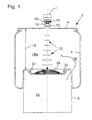
- An air spring 2 usually consists essentially of a cover plate 4, a rolling bellows 6 and a rolling piston 8 (Fig. 1).
- the cover plate 4 is mounted chassisfest on chassis longitudinally.
- the rolling piston 8 is attached to the wheel side.
- Einfederungsvorgang the rolling bellows 6 rolls on the rolling piston 8, wherein the (clear) distance 10 between the cover plate 4 and rolling piston 8 changes accordingly.
- this distance 10 spring height
- the ultrasonic component 14 has a damping transducer 16 mounted on it. With the aid of a reference reflector 18, a reference value can be formed for the purpose of pressure and / or temperature compensation.
- the ultrasonic transducer 16 is arranged so that its main beam 20 is directed toward the center of the rolling piston 8. For the pipe socket 12 is designed so that the free space located in the air spring 2 is not limited by him.
- the annular clamping plate 22 is provided with a convex curved, air-permeable grid covered. This grid serves as a reflector 28 for the of the ultrasonic transducer 16th to be emitted ultrasound signal 20.
- the grid-shaped reflector 28 which is shown in detail in Figures 2 and 3, consists from a sheet-like material with a lattice structure 30.
- the incident ultrasound 20 is sufficiently reflected from this grid-shaped or perforated material 30 is the largest dimension of the mesh (mesh size or hole spacing d) smaller than half Wavelength ⁇ / 2 of the ultrasonic signal (d ⁇ / 2).
- the sheet-like starting material 30 (FIG. 2) can be used for the respective application produce suitable convex reflection surfaces 28 (example: Fig. 3).
Abstract
Description
Eine gattungsgemäße Luftfeder mit den im Oberbegriff des Anspruchs 1 genannten Merkmalen weist eine Ultraschall-Messanordnung zur Bestimmung der Federhöhe nach der Impuls/Echo-Methode auf.A generic air spring with the mentioned in the preamble of claim 1 Features includes an ultrasonic measuring arrangement for determining the spring height the pulse / echo method.
In der Patentschrift EP 844 116 B1 ist eine Einrichtung zur Ultraschall-Abstandsmessung innerhalb der Luftfeder eines Kraftfahrzeugs beschrieben. Die Oberfläche des Reflektors, der auf der Symmetrieachse der Luftfeder angeordnet ist, ist konvex geformt und in Richtung auf den Ultraschall-Sender/Empfänger ausgerichtet. Über die Beschaffenheit des Reflektors und seiner Oberfläche wird weiter nichts ausgesagt.In the patent EP 844 116 B1 is a device for ultrasonic distance measurement described within the air spring of a motor vehicle. The surface of the reflector, which is arranged on the symmetry axis of the air spring is convex and in Direction aligned to the ultrasonic transmitter / receiver. About the nature of the Reflektors and its surface is said nothing more.
Bei Luftfedern, die mit einem internen Anschlagpuffer ausgestattet sind, wird dieser als
Reflektor für die Ultraschall-Abstandsmessung verwendet.
Ein Reflexionskörper mit dem Volumen eines Anschlagpuffers verringert das nutzbare
Federvolumen und verändert dadurch die Kennlinie der Feder. Außerdem erhöht ein
Reflexionskörper mit der Masse eines Anschlagpuffers das Gewicht der Luftfeder.For air springs equipped with an internal stop buffer, this is used as a reflector for ultrasonic distance measurement.
A reflecting body with the volume of a stop buffer reduces the usable spring volume and thereby changes the characteristic of the spring. In addition, a reflection body with the mass of a stop buffer increases the weight of the air spring.
Häufig wird das Volumen des Abrollkolbens als Zusatzvolumen für die Feder genutzt. Befindet sich ein Anschlagpuffer in diesen Federn, so ist dieser mit relativ großen Durchlässen zu versehen, die das Balgvolumen mit dem Kolbenvolumen verbinden. Diese Luftdurchlässe stören die Oberfläche des Reflektors und beeinträchtigen die Ultraschall-Abstandsmessung.Often the volume of the rolling piston is used as additional volume for the spring. If there is a stop buffer in these springs, then this is relatively large To provide passages that connect the bellows volume with the piston volume. These Air diffusers disturb the surface of the reflector and affect the ultrasonic distance measurement.
Zahlreiche Luftfedertypen verfügen jedoch nicht über einen internen Anschlagpuffer. In diesen Fällen ist der Reflektor ein spezielles Bauteil. However, many air spring types do not have an internal stop buffer. In In these cases, the reflector is a special component.
Die Aufgabe der Erfindung besteht in der Schaffung eines Reflektors für Luftfedertypen, die keinen Anschlagpuffer aufweisen und bei denen das Kolbenvolumen als Zusatzvolumen dient. Eine weitere Aufgabe der Erfindung besteht darin, bei Luftfedern mit Anschlagpuffer die im Anschlagpuffer für den Luftdurchtritt notwendige(n) Öffnung(en) zwecks Bildung eines Ultraschall-Reflektors schalltechnisch zu schließen.The object of the invention is to provide a reflector for air spring types, which have no stop buffer and in which the piston volume as Additional volume is used. Another object of the invention is air springs with bump stop the necessary in the bump stop for the passage of air (s) Close the opening (s) for the purpose of forming an ultrasonic reflector.
Der üblicherweise auf dem Kolben angebrachte Reflektor ist gemäß Anspruch 1
luftdurchlässig. Aus diesem Grunde wird der Luftaustausch zwischen Balgvolumen und
Kolbenvolumen nur wenig behindert.
Dieselbe vorteilhafte Wirkung wäre gegeben, wenn sich der Sender/Empfänger ortsfest am
Abrollkolben und sich der Reflektor am Luftfederdeckel mit einem dahinter angeordneten
Zusatzvolumen befände.
Ein flächiges Material mit Gitterstruktur ist nicht nur luftdurchlässig sondern auch leicht.
Es nimmt praktisch kein Bauvolumen ein.
Das Gitter kann die Gestalt eines Drahtgitters oder eines Lochbleches aufweisen. Solange
die Maschenweite bzw. der Lochabstand, d. h. die Gitterkonstante d - und damit auch der
Lochdurchmesser - kleiner als eine halbe Wellenlänge λ/2 des Ultraschallsignals ist
(d < λ/2), wirkt die Reflektoroberfläche für das Ultraschallsignal als stetige Oberfläche.The reflector usually mounted on the piston is permeable to air according to claim 1. For this reason, the air exchange between bellows volume and piston volume is only slightly hindered.
The same advantageous effect would be given if the transmitter / receiver were stationary on the rolling piston and the reflector on the air spring cover with an additional volume arranged behind it.
A flat material with a grid structure is not only breathable but also light. It occupies virtually no volume of construction.
The grid may have the shape of a wire grid or a perforated plate. As long as the mesh size or the hole spacing, ie the lattice constant d - and thus also the hole diameter - smaller than half a wavelength λ / 2 of the ultrasonic signal (d <λ / 2), the reflector surface for the ultrasonic signal acts as a continuous surface.
Aus dem flächigen Drahtgitter lassen sich für die jeweiligen Anwendung geeignete
konvexe Reflexionsflächen herstellen, die sich durch geringes Gewicht und hohe
Luftdurchlässigkeit auszeichnen. Außerdem können notwendige Öffnungen in
Anschlagpuffern von Luftfedern schalltechnisch geschlossen werden ohne der
Luftströmung zu hohen Widerstand zu bieten.
Durch eine konvexe Ausbildung der Reflektoroberfläche werden leichte
Torkelbewegungen der Luftfeder ausgeglichen, so dass in jedem Fall ein praktisch
vertikales Auftreffen des Ultraschallstrahls und damit weitgehend totale Reflexion
gewährleistet ist.From the flat wire mesh suitable convex reflection surfaces can be produced for the respective application, which are characterized by low weight and high air permeability. In addition, necessary openings in stop buffers of air springs can be closed acoustically without providing the air flow to high resistance.
By a convex design of the reflector surface slight Torkelbewegungen the air spring are compensated, so that in each case a virtually vertical impact of the ultrasonic beam and thus largely total reflection is ensured.
Ein Ausführungsbeispiel der Erfindung ist in den Zeichnungen dargestellt. Es zeigt:
Eine Luftfeder 2 besteht üblicherweise im wesentlichen aus einer Abdeckplatte 4, einem
Rollbalg 6 und einem Abrollkolben 8 (Fig. 1). Die Abdeckplatte 4 ist am
Fahrzeuglängsträger chassisfest angebracht. Der Abrollkolben 8 ist radseitig befestigt.
Beim Einfederungsvorgang rollt der Rollbalg 6 auf dem Abrollkolben 8 ab, wobei sich der
(lichte) Abstand 10 zwischen Abdeckplatte 4 und Abrollkolben 8 entsprechend ändert. Zur
Bestimmung der Fahrhöhe gilt es, diesen Abstand 10 (Federhöhe) zu messen.
Zu diesem Zweck befindet sich in der Abdeckplatte 4 ein Rohrstutzen 12 mit einer als
Sender und Empfänger ausgebildeten Ultraschallkomponente 14.An
For this purpose, located in the
Die Ultraschallkomponente 14 weist einen dämpfend gelagerten Ultraschallwandler 16 auf.
Mit Hilfe eines Referenzreflektors 18 kann zwecks Druck- und/oder
Temperaturkompensation ein Referenzwert gebildet werden.
Der Ultraschallwandler 16 ist so angeordnet, dass sein Hauptstrahl 20 in Richtung auf die
Mitte des Abrollkolbens 8 gerichtet ist. Dafür ist der Rohrstutzen 12 so gestaltet, dass der
in der Luftfeder 2 befindliche Freiraum durch ihn nicht eingeschränkt wird. The
The
Zur Befestigung des Rollbalgs 6 weist der Abrollkolben 8 einen Spannteller 22 auf. Der
Spannteller 22 besteht nicht - wie üblich - aus einer in sich geschlossenen Platte sondern
ist ringförmig ausgebildet, so dass unter Hinzunahme des Abrollkolben-Innenraums 24 das
wirksame Luftfeder-Volumen 26 entsprechend größer ist: wirksames Luftfedervolumen 26
= Abrollkolben-Innenraum 24 + variables Rollbalg-Volumen 26a.For fastening the
Der ringförmige Spannteller 22 ist mit einem konvexgewölbten, luftdurchlässigen Gitter
abgedeckt. Dieses Gitter dient als Reflektor 28 für das von dem Ultraschallwandler 16
abzustrahlende Ultraschallsignal 20.The
Der gitterförmige Reflektor 28, der im Detail in den Figuren 2 und 3 dargestellt ist, besteht
aus einem flächigen Material mit Gitterstruktur 30. Damit der auftreffende Ultraschall 20
von diesem gitterförmigen oder gelochten Material 30 hinreichend reflektiert wird, ist die
größte Abmessung der Maschen (Maschenweite bzw. Lochabstand d) kleiner als die halbe
Wellenlänge λ/2 des Ultraschallsignals (d < λ/2).The grid-
Aus dem flächigen Ausgangsmaterial 30 (Fig. 2) lassen sich für die jeweilige Anwendung geeignete konvexe Reflexionsflächen 28 herstellen (Beispiel: Fig. 3). The sheet-like starting material 30 (FIG. 2) can be used for the respective application produce suitable convex reflection surfaces 28 (example: Fig. 3).
- 22
- Luftfederair spring
- 44
- Abdeckplattecover
- 66
- Rollbalgbellows
- 88th
- Abrollkolbenroll-off
- 4,84.8
- Endgliederend links
- 1010
- (lichter) Abstand zwischen Abdeckplatte (4) und Abrollkolben (8), Federhöhe(clear) distance between cover plate (4) and rolling piston (8), spring height
- 1212
- Rohrstutzenpipe socket
- 1414
- Sender/Empfänger, UltraschallkomponenteTransmitter / receiver, ultrasonic component
- 1616
- Ultraschallwandlerultrasound transducer
- 1818
- Referenzreflektorreference reflector
- 2020
- Hauptstrahl, Ultraschallsignal, UltraschallMain beam, ultrasonic signal, ultrasound
- 2222
- Spanntellerclamping plate
- 2424
- Innenraum des Abrollkolbens (8), ZusatzvolumenInterior of the rolling piston (8), additional volume
- 2626
- Luftfedervolumen, wirksames VolumenAir spring volume, effective volume
- 26a26a
- (variables) Rollbalgvolumen(variable) rolling bellows volume
- 2828
- Gitter, Reflektor, ReflexionsflächeGrid, reflector, reflection surface
- dd
- Maschenweite bzw. LochabstandMesh size or hole spacing
- 3030
- flächiges Material mit Gitterstruktur, Drahtgitter, Lochblechflat material with grid structure, wire mesh, perforated metal sheet
Claims (7)
dadurch gekennzeichnet, dass der Reflektor (28) die Abdeckung eines Zusatzvolumens (24) bildet.Air spring according to claim 1,
characterized in that the reflector (28) forms the cover of an additional volume (24).
dadurch gekennzeichnet, dass das Volumen (24) des Abrollkolbens (8) als Zusatzvolumen dient.Air spring according to claim 1 or 2,
characterized in that the volume (24) of the rolling piston (8) serves as additional volume.
dadurch gekennzeichnet, dass der Reflektor (28) aus einem flächigen Material (30) besteht, das eine Gitterstruktur aufweist.Air spring according to one of claims 1 to 3,
characterized in that the reflector (28) consists of a sheet material (30) having a grid structure.
dadurch gekennzeichnet, dass die Gitterstruktur von einem Drahtgitter oder einem Lochblech (30) gebildet wird.Air spring according to claim 4,
characterized in that the grid structure is formed by a wire mesh or a perforated plate (30).
dadurch gekennzeichnet, dass die größte Abmessung der Maschen (Maschenweite bzw. Lochabstand d) kleiner als die halbe Wellenlänge (λ/2) des Ultraschallsignals (20) ist (d < λ/2).Air spring according to one of claims 1 to 5,
characterized in that the largest dimension of the mesh (mesh size or hole spacing d) is smaller than half the wavelength (λ / 2) of the ultrasonic signal (20) (d <λ / 2).
dadurch gekennzeichnet, dass der Reflektor (28) konvex geformt ist und in Richtung auf den Ultraschall-Sender/Empfänger (14) ausgerichtet ist.Air spring according to one of claims 1 to 6,
characterized in that the reflector (28) is convex shaped and oriented towards the ultrasonic transmitter / receiver (14).
Applications Claiming Priority (2)
| Application Number | Priority Date | Filing Date | Title |
|---|---|---|---|
| DE10349797A DE10349797A1 (en) | 2003-10-24 | 2003-10-24 | Air spring with ultrasonic measuring arrangement |
| DE10349797 | 2003-10-24 |
Publications (2)
| Publication Number | Publication Date |
|---|---|
| EP1526014A1 true EP1526014A1 (en) | 2005-04-27 |
| EP1526014B1 EP1526014B1 (en) | 2007-05-09 |
Family
ID=34384465
Family Applications (1)
| Application Number | Title | Priority Date | Filing Date |
|---|---|---|---|
| EP04104507A Not-in-force EP1526014B1 (en) | 2003-10-24 | 2004-09-17 | Air spring with ultrasound measuring arrangement |
Country Status (3)
| Country | Link |
|---|---|
| EP (1) | EP1526014B1 (en) |
| AT (1) | ATE361849T1 (en) |
| DE (2) | DE10349797A1 (en) |
Cited By (2)
| Publication number | Priority date | Publication date | Assignee | Title |
|---|---|---|---|---|
| WO2007137647A1 (en) * | 2006-05-31 | 2007-12-06 | Contitech Luftfedersysteme Gmbh | Determination of the spring level of an air spring after a pulse delay time measuring process |
| EP3640497A1 (en) * | 2018-10-12 | 2020-04-22 | ContiTech Luftfedersysteme GmbH | Gas spring with a device for determining the axial spacing of two end elements of the same |
Families Citing this family (2)
| Publication number | Priority date | Publication date | Assignee | Title |
|---|---|---|---|---|
| DE102008033820B4 (en) | 2008-07-19 | 2015-06-25 | Audi Ag | Motor vehicle with active suspension |
| DE102010060293A1 (en) | 2010-11-01 | 2012-05-03 | Contitech Luftfedersysteme Gmbh | Ultrasound level control device for commercial vehicle, has ultrasonic sensor and reflector hermetically separated by elastic protective bellow from environment lying outside of elastic protective bellow |
Citations (4)
| Publication number | Priority date | Publication date | Assignee | Title |
|---|---|---|---|---|
| DE3423602A1 (en) * | 1984-06-27 | 1986-01-09 | Robert Bosch Gmbh, 7000 Stuttgart | Device for measuring the distance between the chassis and the axle of a vehicle |
| EP0844116A1 (en) * | 1996-11-21 | 1998-05-27 | ContiTech Luftfedersysteme GmbH | Air spring system for a motor vehicle |
| DE19701530C1 (en) * | 1997-01-17 | 1998-08-06 | Contitech Luftfedersyst Gmbh | Axial distance determination between end members of compressed gas spring for vehicle |
| EP1295737A2 (en) * | 2001-09-25 | 2003-03-26 | KNORR-BREMSE SYSTEME FÜR NUTZFAHRZEUGE GmbH | Determination of height and pressure in spring elements, especially air springs, for vehicles |
Family Cites Families (1)
| Publication number | Priority date | Publication date | Assignee | Title |
|---|---|---|---|---|
| DE19820877C2 (en) * | 1998-05-09 | 2002-09-19 | Contitech Luftfedersyst Gmbh | Non-contact distance and pressure measurement within an air spring |
-
2003
- 2003-10-24 DE DE10349797A patent/DE10349797A1/en not_active Withdrawn
-
2004
- 2004-09-17 DE DE502004003746T patent/DE502004003746D1/en active Active
- 2004-09-17 EP EP04104507A patent/EP1526014B1/en not_active Not-in-force
- 2004-09-17 AT AT04104507T patent/ATE361849T1/en not_active IP Right Cessation
Patent Citations (5)
| Publication number | Priority date | Publication date | Assignee | Title |
|---|---|---|---|---|
| DE3423602A1 (en) * | 1984-06-27 | 1986-01-09 | Robert Bosch Gmbh, 7000 Stuttgart | Device for measuring the distance between the chassis and the axle of a vehicle |
| EP0844116A1 (en) * | 1996-11-21 | 1998-05-27 | ContiTech Luftfedersysteme GmbH | Air spring system for a motor vehicle |
| EP0844116B1 (en) | 1996-11-21 | 2001-04-18 | ContiTech Luftfedersysteme GmbH | Air spring system for a motor vehicle |
| DE19701530C1 (en) * | 1997-01-17 | 1998-08-06 | Contitech Luftfedersyst Gmbh | Axial distance determination between end members of compressed gas spring for vehicle |
| EP1295737A2 (en) * | 2001-09-25 | 2003-03-26 | KNORR-BREMSE SYSTEME FÜR NUTZFAHRZEUGE GmbH | Determination of height and pressure in spring elements, especially air springs, for vehicles |
Cited By (2)
| Publication number | Priority date | Publication date | Assignee | Title |
|---|---|---|---|---|
| WO2007137647A1 (en) * | 2006-05-31 | 2007-12-06 | Contitech Luftfedersysteme Gmbh | Determination of the spring level of an air spring after a pulse delay time measuring process |
| EP3640497A1 (en) * | 2018-10-12 | 2020-04-22 | ContiTech Luftfedersysteme GmbH | Gas spring with a device for determining the axial spacing of two end elements of the same |
Also Published As
| Publication number | Publication date |
|---|---|
| ATE361849T1 (en) | 2007-06-15 |
| EP1526014B1 (en) | 2007-05-09 |
| DE502004003746D1 (en) | 2007-06-21 |
| DE10349797A1 (en) | 2005-05-25 |
Similar Documents
| Publication | Publication Date | Title |
|---|---|---|
| DE102005006914B4 (en) | Device for sound coupling between an intake tract and / or engine compartment and a vehicle interior of a motor vehicle | |
| DE3843033C2 (en) | ||
| EP1526014B1 (en) | Air spring with ultrasound measuring arrangement | |
| WO2006063873A1 (en) | Ultrasonic measuring device comprising cross-section contractions on the flow pipe | |
| AT501671A2 (en) | MUFFLER FOR USE IN A VACUUM CLEANER | |
| EP0249689A1 (en) | Sensor for the determination of the flow of a flowing fluid | |
| CH652359A5 (en) | SHOCK ABSORBER DEVICE FOR DAMPING IMPACT SHOCKS FOR VEHICLES AND SHOCK ABSORBER DEVICE ON A VEHICLE WITH THE SAME. | |
| DE4413894C2 (en) | Bending converter in pot form | |
| EP2639788B1 (en) | Ultrasound sensor | |
| DE10034243B4 (en) | Silencer for inlet and / or outlet in compressed air systems | |
| DE102009052199A1 (en) | Silencer for side panel | |
| DE1462236A1 (en) | Treble resonator for a microphone system | |
| DE102008011087A1 (en) | Air intake housing with a perforated sound attenuation wall | |
| DE69818687T2 (en) | pulsation | |
| EP3326001B1 (en) | Acoustic sensor for transmitting and/or receiving acoustic signals | |
| EP0680866A1 (en) | Assembly for reducing tyre/road surface noise | |
| DE2621725B2 (en) | Rubber mount with hydraulic damping | |
| DE10222507A1 (en) | Device for noise shaping in a motor vehicle | |
| DE202014101267U1 (en) | Device for influencing sound or sound energy | |
| DE60004045T2 (en) | BENDING SHAFT ACOUSTIC DEVICE | |
| EP0782935A2 (en) | Vehicle with tyres and having at least one noise reducing device | |
| DE10332984B4 (en) | Swivel motor for a split stabilizer | |
| DE102016115199A1 (en) | Ultrasonic sensor for determining or monitoring a process variable of a medium in automation technology | |
| EP0821823B1 (en) | Sound damper for ultrasonic waves | |
| DE2303611A1 (en) | SILENCER |
Legal Events
| Date | Code | Title | Description |
|---|---|---|---|
| PUAI | Public reference made under article 153(3) epc to a published international application that has entered the european phase |
Free format text: ORIGINAL CODE: 0009012 |
|
| AK | Designated contracting states |
Kind code of ref document: A1 Designated state(s): AT BE BG CH CY CZ DE DK EE ES FI FR GB GR HU IE IT LI LU MC NL PL PT RO SE SI SK TR |
|
| AX | Request for extension of the european patent |
Extension state: AL HR LT LV MK |
|
| 17P | Request for examination filed |
Effective date: 20051027 |
|
| AKX | Designation fees paid |
Designated state(s): AT BE BG CH CY CZ DE DK EE ES FI FR GB GR HU IE IT LI LU MC NL PL PT RO SE SI SK TR |
|
| GRAP | Despatch of communication of intention to grant a patent |
Free format text: ORIGINAL CODE: EPIDOSNIGR1 |
|
| GRAS | Grant fee paid |
Free format text: ORIGINAL CODE: EPIDOSNIGR3 |
|
| GRAA | (expected) grant |
Free format text: ORIGINAL CODE: 0009210 |
|
| AK | Designated contracting states |
Kind code of ref document: B1 Designated state(s): AT BE BG CH CY CZ DE DK EE ES FI FR GB GR HU IE IT LI LU MC NL PL PT RO SE SI SK TR |
|
| PG25 | Lapsed in a contracting state [announced via postgrant information from national office to epo] |
Ref country code: FI Free format text: LAPSE BECAUSE OF FAILURE TO SUBMIT A TRANSLATION OF THE DESCRIPTION OR TO PAY THE FEE WITHIN THE PRESCRIBED TIME-LIMIT Effective date: 20070509 |
|
| REG | Reference to a national code |
Ref country code: GB Ref legal event code: FG4D Free format text: NOT ENGLISH |
|
| REG | Reference to a national code |
Ref country code: CH Ref legal event code: EP |
|
| REG | Reference to a national code |
Ref country code: IE Ref legal event code: FG4D Free format text: LANGUAGE OF EP DOCUMENT: GERMAN |
|
| REF | Corresponds to: |
Ref document number: 502004003746 Country of ref document: DE Date of ref document: 20070621 Kind code of ref document: P |
|
| REG | Reference to a national code |
Ref country code: SE Ref legal event code: TRGR |
|
| PG25 | Lapsed in a contracting state [announced via postgrant information from national office to epo] |
Ref country code: ES Free format text: LAPSE BECAUSE OF FAILURE TO SUBMIT A TRANSLATION OF THE DESCRIPTION OR TO PAY THE FEE WITHIN THE PRESCRIBED TIME-LIMIT Effective date: 20070820 |
|
| ET | Fr: translation filed | ||
| PG25 | Lapsed in a contracting state [announced via postgrant information from national office to epo] |
Ref country code: PL Free format text: LAPSE BECAUSE OF FAILURE TO SUBMIT A TRANSLATION OF THE DESCRIPTION OR TO PAY THE FEE WITHIN THE PRESCRIBED TIME-LIMIT Effective date: 20070509 |
|
| GBV | Gb: ep patent (uk) treated as always having been void in accordance with gb section 77(7)/1977 [no translation filed] |
Effective date: 20070509 |
|
| REG | Reference to a national code |
Ref country code: IE Ref legal event code: FD4D |
|
| PG25 | Lapsed in a contracting state [announced via postgrant information from national office to epo] |
Ref country code: SI Free format text: LAPSE BECAUSE OF FAILURE TO SUBMIT A TRANSLATION OF THE DESCRIPTION OR TO PAY THE FEE WITHIN THE PRESCRIBED TIME-LIMIT Effective date: 20070509 Ref country code: DK Free format text: LAPSE BECAUSE OF FAILURE TO SUBMIT A TRANSLATION OF THE DESCRIPTION OR TO PAY THE FEE WITHIN THE PRESCRIBED TIME-LIMIT Effective date: 20070509 Ref country code: CZ Free format text: LAPSE BECAUSE OF FAILURE TO SUBMIT A TRANSLATION OF THE DESCRIPTION OR TO PAY THE FEE WITHIN THE PRESCRIBED TIME-LIMIT Effective date: 20070509 Ref country code: IE Free format text: LAPSE BECAUSE OF FAILURE TO SUBMIT A TRANSLATION OF THE DESCRIPTION OR TO PAY THE FEE WITHIN THE PRESCRIBED TIME-LIMIT Effective date: 20070509 Ref country code: PT Free format text: LAPSE BECAUSE OF FAILURE TO SUBMIT A TRANSLATION OF THE DESCRIPTION OR TO PAY THE FEE WITHIN THE PRESCRIBED TIME-LIMIT Effective date: 20071009 Ref country code: BG Free format text: LAPSE BECAUSE OF FAILURE TO SUBMIT A TRANSLATION OF THE DESCRIPTION OR TO PAY THE FEE WITHIN THE PRESCRIBED TIME-LIMIT Effective date: 20070809 |
|
| PG25 | Lapsed in a contracting state [announced via postgrant information from national office to epo] |
Ref country code: SK Free format text: LAPSE BECAUSE OF FAILURE TO SUBMIT A TRANSLATION OF THE DESCRIPTION OR TO PAY THE FEE WITHIN THE PRESCRIBED TIME-LIMIT Effective date: 20070509 |
|
| PLBE | No opposition filed within time limit |
Free format text: ORIGINAL CODE: 0009261 |
|
| STAA | Information on the status of an ep patent application or granted ep patent |
Free format text: STATUS: NO OPPOSITION FILED WITHIN TIME LIMIT |
|
| BERE | Be: lapsed |
Owner name: CONTITECH LUFTFEDERSYSTEME G.M.B.H. Effective date: 20070930 |
|
| 26N | No opposition filed |
Effective date: 20080212 |
|
| PG25 | Lapsed in a contracting state [announced via postgrant information from national office to epo] |
Ref country code: MC Free format text: LAPSE BECAUSE OF NON-PAYMENT OF DUE FEES Effective date: 20070930 Ref country code: GR Free format text: LAPSE BECAUSE OF FAILURE TO SUBMIT A TRANSLATION OF THE DESCRIPTION OR TO PAY THE FEE WITHIN THE PRESCRIBED TIME-LIMIT Effective date: 20070810 Ref country code: GB Free format text: LAPSE BECAUSE OF FAILURE TO SUBMIT A TRANSLATION OF THE DESCRIPTION OR TO PAY THE FEE WITHIN THE PRESCRIBED TIME-LIMIT Effective date: 20070509 |
|
| PG25 | Lapsed in a contracting state [announced via postgrant information from national office to epo] |
Ref country code: RO Free format text: LAPSE BECAUSE OF FAILURE TO SUBMIT A TRANSLATION OF THE DESCRIPTION OR TO PAY THE FEE WITHIN THE PRESCRIBED TIME-LIMIT Effective date: 20070509 |
|
| PG25 | Lapsed in a contracting state [announced via postgrant information from national office to epo] |
Ref country code: BE Free format text: LAPSE BECAUSE OF NON-PAYMENT OF DUE FEES Effective date: 20070930 |
|
| PG25 | Lapsed in a contracting state [announced via postgrant information from national office to epo] |
Ref country code: AT Free format text: LAPSE BECAUSE OF NON-PAYMENT OF DUE FEES Effective date: 20070917 |
|
| PG25 | Lapsed in a contracting state [announced via postgrant information from national office to epo] |
Ref country code: EE Free format text: LAPSE BECAUSE OF FAILURE TO SUBMIT A TRANSLATION OF THE DESCRIPTION OR TO PAY THE FEE WITHIN THE PRESCRIBED TIME-LIMIT Effective date: 20070509 |
|
| REG | Reference to a national code |
Ref country code: CH Ref legal event code: PL |
|
| PG25 | Lapsed in a contracting state [announced via postgrant information from national office to epo] |
Ref country code: LI Free format text: LAPSE BECAUSE OF NON-PAYMENT OF DUE FEES Effective date: 20070930 Ref country code: CH Free format text: LAPSE BECAUSE OF NON-PAYMENT OF DUE FEES Effective date: 20070930 |
|
| PG25 | Lapsed in a contracting state [announced via postgrant information from national office to epo] |
Ref country code: CY Free format text: LAPSE BECAUSE OF FAILURE TO SUBMIT A TRANSLATION OF THE DESCRIPTION OR TO PAY THE FEE WITHIN THE PRESCRIBED TIME-LIMIT Effective date: 20070509 |
|
| PG25 | Lapsed in a contracting state [announced via postgrant information from national office to epo] |
Ref country code: LU Free format text: LAPSE BECAUSE OF NON-PAYMENT OF DUE FEES Effective date: 20070917 |
|
| PG25 | Lapsed in a contracting state [announced via postgrant information from national office to epo] |
Ref country code: HU Free format text: LAPSE BECAUSE OF FAILURE TO SUBMIT A TRANSLATION OF THE DESCRIPTION OR TO PAY THE FEE WITHIN THE PRESCRIBED TIME-LIMIT Effective date: 20071110 Ref country code: TR Free format text: LAPSE BECAUSE OF FAILURE TO SUBMIT A TRANSLATION OF THE DESCRIPTION OR TO PAY THE FEE WITHIN THE PRESCRIBED TIME-LIMIT Effective date: 20070509 |
|
| PG25 | Lapsed in a contracting state [announced via postgrant information from national office to epo] |
Ref country code: LI Free format text: LAPSE BECAUSE OF NON-PAYMENT OF DUE FEES Effective date: 20080930 Ref country code: CH Free format text: LAPSE BECAUSE OF NON-PAYMENT OF DUE FEES Effective date: 20080930 |
|
| PGFP | Annual fee paid to national office [announced via postgrant information from national office to epo] |
Ref country code: SE Payment date: 20140918 Year of fee payment: 11 Ref country code: FR Payment date: 20140919 Year of fee payment: 11 |
|
| PGFP | Annual fee paid to national office [announced via postgrant information from national office to epo] |
Ref country code: IT Payment date: 20140923 Year of fee payment: 11 |
|
| PGFP | Annual fee paid to national office [announced via postgrant information from national office to epo] |
Ref country code: NL Payment date: 20140918 Year of fee payment: 11 |
|
| PG25 | Lapsed in a contracting state [announced via postgrant information from national office to epo] |
Ref country code: IT Free format text: LAPSE BECAUSE OF NON-PAYMENT OF DUE FEES Effective date: 20150917 |
|
| REG | Reference to a national code |
Ref country code: SE Ref legal event code: EUG |
|
| PG25 | Lapsed in a contracting state [announced via postgrant information from national office to epo] |
Ref country code: SE Free format text: LAPSE BECAUSE OF NON-PAYMENT OF DUE FEES Effective date: 20150918 |
|
| REG | Reference to a national code |
Ref country code: NL Ref legal event code: MM Effective date: 20151001 |
|
| REG | Reference to a national code |
Ref country code: FR Ref legal event code: ST Effective date: 20160531 |
|
| PG25 | Lapsed in a contracting state [announced via postgrant information from national office to epo] |
Ref country code: FR Free format text: LAPSE BECAUSE OF NON-PAYMENT OF DUE FEES Effective date: 20150930 Ref country code: NL Free format text: LAPSE BECAUSE OF NON-PAYMENT OF DUE FEES Effective date: 20151001 |
|
| PGFP | Annual fee paid to national office [announced via postgrant information from national office to epo] |
Ref country code: DE Payment date: 20180930 Year of fee payment: 15 |
|
| REG | Reference to a national code |
Ref country code: DE Ref legal event code: R119 Ref document number: 502004003746 Country of ref document: DE |
|
| PG25 | Lapsed in a contracting state [announced via postgrant information from national office to epo] |
Ref country code: DE Free format text: LAPSE BECAUSE OF NON-PAYMENT OF DUE FEES Effective date: 20200401 |