EP1525141B1 - Contact lens package and method for reducing the adherence of a contact lens to its package - Google Patents
Contact lens package and method for reducing the adherence of a contact lens to its package Download PDFInfo
- Publication number
- EP1525141B1 EP1525141B1 EP03739210.7A EP03739210A EP1525141B1 EP 1525141 B1 EP1525141 B1 EP 1525141B1 EP 03739210 A EP03739210 A EP 03739210A EP 1525141 B1 EP1525141 B1 EP 1525141B1
- Authority
- EP
- European Patent Office
- Prior art keywords
- cavity
- package
- contact lens
- percent
- flange
- Prior art date
- Legal status (The legal status is an assumption and is not a legal conclusion. Google has not performed a legal analysis and makes no representation as to the accuracy of the status listed.)
- Expired - Lifetime
Links
- 238000000034 method Methods 0.000 title claims description 17
- 238000013461 design Methods 0.000 claims description 12
- 239000000243 solution Substances 0.000 description 19
- -1 polypropylene Polymers 0.000 description 13
- 239000004743 Polypropylene Substances 0.000 description 11
- 229920001155 polypropylene Polymers 0.000 description 11
- 239000000017 hydrogel Substances 0.000 description 9
- 239000011324 bead Substances 0.000 description 7
- 239000011521 glass Substances 0.000 description 7
- 239000000463 material Substances 0.000 description 7
- 229920001296 polysiloxane Polymers 0.000 description 7
- 206010028197 multiple epiphyseal dysplasia Diseases 0.000 description 6
- 230000000887 hydrating effect Effects 0.000 description 5
- PXHVJJICTQNCMI-UHFFFAOYSA-N Nickel Chemical compound [Ni] PXHVJJICTQNCMI-UHFFFAOYSA-N 0.000 description 4
- FAPWRFPIFSIZLT-UHFFFAOYSA-M Sodium chloride Chemical compound [Na+].[Cl-] FAPWRFPIFSIZLT-UHFFFAOYSA-M 0.000 description 4
- 238000004806 packaging method and process Methods 0.000 description 4
- 241001427960 Astrophytum asterias Species 0.000 description 3
- 238000005422 blasting Methods 0.000 description 3
- 238000001746 injection moulding Methods 0.000 description 3
- 238000004519 manufacturing process Methods 0.000 description 3
- 239000000155 melt Substances 0.000 description 3
- 238000007788 roughening Methods 0.000 description 3
- 230000001954 sterilising effect Effects 0.000 description 3
- 238000004659 sterilization and disinfection Methods 0.000 description 3
- 238000011282 treatment Methods 0.000 description 3
- UURVHRGPGCBHIC-UHFFFAOYSA-N 3-(ethenoxycarbonylamino)propanoic acid 4-[[[[[[[[[[[[[[[[[[[[[[[[[[[4-ethenoxycarbonyloxybutyl(dimethyl)silyl]oxy-dimethylsilyl]oxy-dimethylsilyl]oxy-dimethylsilyl]oxy-dimethylsilyl]oxy-dimethylsilyl]oxy-dimethylsilyl]oxy-dimethylsilyl]oxy-dimethylsilyl]oxy-dimethylsilyl]oxy-dimethylsilyl]oxy-dimethylsilyl]oxy-dimethylsilyl]oxy-dimethylsilyl]oxy-dimethylsilyl]oxy-dimethylsilyl]oxy-dimethylsilyl]oxy-dimethylsilyl]oxy-dimethylsilyl]oxy-dimethylsilyl]oxy-dimethylsilyl]oxy-dimethylsilyl]oxy-dimethylsilyl]oxy-dimethylsilyl]oxy-dimethylsilyl]oxy-dimethylsilyl]oxy-dimethylsilyl]butyl ethenyl carbonate 1-ethenylpyrrolidin-2-one ethenyl N-[3-tris(trimethylsilyloxy)silylpropyl]carbamate Chemical compound C=CN1CCCC1=O.OC(=O)CCNC(=O)OC=C.C[Si](C)(C)O[Si](CCCNC(=O)OC=C)(O[Si](C)(C)C)O[Si](C)(C)C.C[Si](C)(CCCCOC(=O)OC=C)O[Si](C)(C)O[Si](C)(C)O[Si](C)(C)O[Si](C)(C)O[Si](C)(C)O[Si](C)(C)O[Si](C)(C)O[Si](C)(C)O[Si](C)(C)O[Si](C)(C)O[Si](C)(C)O[Si](C)(C)O[Si](C)(C)O[Si](C)(C)O[Si](C)(C)O[Si](C)(C)O[Si](C)(C)O[Si](C)(C)O[Si](C)(C)O[Si](C)(C)O[Si](C)(C)O[Si](C)(C)O[Si](C)(C)O[Si](C)(C)O[Si](C)(C)O[Si](C)(C)CCCCOC(=O)OC=C UURVHRGPGCBHIC-UHFFFAOYSA-N 0.000 description 2
- 239000004698 Polyethylene Substances 0.000 description 2
- 239000012467 final product Substances 0.000 description 2
- 239000011888 foil Substances 0.000 description 2
- 230000036571 hydration Effects 0.000 description 2
- 238000006703 hydration reaction Methods 0.000 description 2
- 230000002209 hydrophobic effect Effects 0.000 description 2
- 238000002347 injection Methods 0.000 description 2
- 239000007924 injection Substances 0.000 description 2
- 238000003698 laser cutting Methods 0.000 description 2
- 239000000203 mixture Substances 0.000 description 2
- 229910052759 nickel Inorganic materials 0.000 description 2
- 230000003287 optical effect Effects 0.000 description 2
- 238000012856 packing Methods 0.000 description 2
- 230000010399 physical interaction Effects 0.000 description 2
- 229920000573 polyethylene Polymers 0.000 description 2
- 238000002360 preparation method Methods 0.000 description 2
- 229920000089 Cyclic olefin copolymer Polymers 0.000 description 1
- 229920001616 Polymacon Polymers 0.000 description 1
- 229920006397 acrylic thermoplastic Polymers 0.000 description 1
- 239000000853 adhesive Substances 0.000 description 1
- 230000001070 adhesive effect Effects 0.000 description 1
- 229910052782 aluminium Inorganic materials 0.000 description 1
- XAGFODPZIPBFFR-UHFFFAOYSA-N aluminium Chemical compound [Al] XAGFODPZIPBFFR-UHFFFAOYSA-N 0.000 description 1
- 239000007864 aqueous solution Substances 0.000 description 1
- 239000000872 buffer Substances 0.000 description 1
- 229920001577 copolymer Polymers 0.000 description 1
- 238000012937 correction Methods 0.000 description 1
- 239000002537 cosmetic Substances 0.000 description 1
- 238000011161 development Methods 0.000 description 1
- 230000018109 developmental process Effects 0.000 description 1
- 229920001971 elastomer Polymers 0.000 description 1
- 238000007667 floating Methods 0.000 description 1
- 238000009472 formulation Methods 0.000 description 1
- 238000007689 inspection Methods 0.000 description 1
- 239000007788 liquid Substances 0.000 description 1
- 238000003754 machining Methods 0.000 description 1
- 229910052751 metal Inorganic materials 0.000 description 1
- 239000002184 metal Substances 0.000 description 1
- 238000000465 moulding Methods 0.000 description 1
- 229920001778 nylon Polymers 0.000 description 1
- 229920003229 poly(methyl methacrylate) Polymers 0.000 description 1
- 239000004417 polycarbonate Substances 0.000 description 1
- 229920000515 polycarbonate Polymers 0.000 description 1
- 229920000642 polymer Polymers 0.000 description 1
- 239000005060 rubber Substances 0.000 description 1
- 238000007789 sealing Methods 0.000 description 1
- 229920002379 silicone rubber Polymers 0.000 description 1
- NLAIHECABDOZBR-UHFFFAOYSA-M sodium 2,2-bis(2-methylprop-2-enoyloxymethyl)butyl 2-methylprop-2-enoate 2-hydroxyethyl 2-methylprop-2-enoate 2-methylprop-2-enoate Chemical compound [Na+].CC(=C)C([O-])=O.CC(=C)C(=O)OCCO.CCC(COC(=O)C(C)=C)(COC(=O)C(C)=C)COC(=O)C(C)=C NLAIHECABDOZBR-UHFFFAOYSA-M 0.000 description 1
- 239000007921 spray Substances 0.000 description 1
- 239000000126 substance Substances 0.000 description 1
- 230000003746 surface roughness Effects 0.000 description 1
- ISXSCDLOGDJUNJ-UHFFFAOYSA-N tert-butyl prop-2-enoate Chemical compound CC(C)(C)OC(=O)C=C ISXSCDLOGDJUNJ-UHFFFAOYSA-N 0.000 description 1
- 238000012360 testing method Methods 0.000 description 1
- 150000003673 urethanes Chemical class 0.000 description 1
- XLYOFNOQVPJJNP-UHFFFAOYSA-N water Substances O XLYOFNOQVPJJNP-UHFFFAOYSA-N 0.000 description 1
Images



Classifications
-
- A—HUMAN NECESSITIES
- A45—HAND OR TRAVELLING ARTICLES
- A45C—PURSES; LUGGAGE; HAND CARRIED BAGS
- A45C11/00—Receptacles for purposes not provided for in groups A45C1/00-A45C9/00
- A45C11/005—Contact lens cases
-
- A—HUMAN NECESSITIES
- A45—HAND OR TRAVELLING ARTICLES
- A45C—PURSES; LUGGAGE; HAND CARRIED BAGS
- A45C11/00—Receptacles for purposes not provided for in groups A45C1/00-A45C9/00
- A45C11/04—Spectacle cases; Pince-nez cases
- A45C11/046—Spectacle cases; Pince-nez cases with contact lens holders
-
- B—PERFORMING OPERATIONS; TRANSPORTING
- B65—CONVEYING; PACKING; STORING; HANDLING THIN OR FILAMENTARY MATERIAL
- B65D—CONTAINERS FOR STORAGE OR TRANSPORT OF ARTICLES OR MATERIALS, e.g. BAGS, BARRELS, BOTTLES, BOXES, CANS, CARTONS, CRATES, DRUMS, JARS, TANKS, HOPPERS, FORWARDING CONTAINERS; ACCESSORIES, CLOSURES, OR FITTINGS THEREFOR; PACKAGING ELEMENTS; PACKAGES
- B65D75/00—Packages comprising articles or materials partially or wholly enclosed in strips, sheets, blanks, tubes or webs of flexible sheet material, e.g. in folded wrappers
- B65D75/28—Articles or materials wholly enclosed in composite wrappers, i.e. wrappers formed by associating or interconnecting two or more sheets or blanks
- B65D75/30—Articles or materials enclosed between two opposed sheets or blanks having their margins united, e.g. by pressure-sensitive adhesive, crimping, heat-sealing, or welding
- B65D75/32—Articles or materials enclosed between two opposed sheets or blanks having their margins united, e.g. by pressure-sensitive adhesive, crimping, heat-sealing, or welding one or both sheets or blanks being recessed to accommodate contents
- B65D75/36—Articles or materials enclosed between two opposed sheets or blanks having their margins united, e.g. by pressure-sensitive adhesive, crimping, heat-sealing, or welding one or both sheets or blanks being recessed to accommodate contents one sheet or blank being recessed and the other formed of relatively stiff flat sheet material, e.g. blister packages, the recess or recesses being preformed
-
- B—PERFORMING OPERATIONS; TRANSPORTING
- B65—CONVEYING; PACKING; STORING; HANDLING THIN OR FILAMENTARY MATERIAL
- B65D—CONTAINERS FOR STORAGE OR TRANSPORT OF ARTICLES OR MATERIALS, e.g. BAGS, BARRELS, BOTTLES, BOXES, CANS, CARTONS, CRATES, DRUMS, JARS, TANKS, HOPPERS, FORWARDING CONTAINERS; ACCESSORIES, CLOSURES, OR FITTINGS THEREFOR; PACKAGING ELEMENTS; PACKAGES
- B65D2585/00—Containers, packaging elements or packages specially adapted for particular articles or materials
- B65D2585/54—Containers, packaging elements or packages specially adapted for particular articles or materials for articles of special shape not otherwise provided for
- B65D2585/545—Contact lenses
Definitions
- This invention relates to a package for storing a contact lens as well as a method of reducing the adherence of a contact lens to its package.
- This invention includes a package for storing a contact lens in a solution as recited in the claims
- the invention includes a method of reducing the adherence of a contact lens to its package as recite in the claims.
- a "medical device” is any device that is used to treat a human condition and is packaged in a solution.
- medical devices include but are not limited to ophthalmic devices that reside in or on the eye.
- Ophthalmic devices includes but are not limited to soft contact lenses, intraocular lenses, overlay lenses, ocular inserts, and optical inserts. These devices can provide optical correction or may be cosmetic.
- the preferred medical devices of the invention are soft contact lenses made from silicone elastomers or hydrogels, which include but are not limited to silicone hydrogels, and fluorohydrogels.
- Soft contact lens formulations are disclosed in US Patent No. 5,710,302 , WO 9421698 , EP 406161 , JP 2000016905 , U.S. Pat.
- the particularly preferred medical devices of the invention are soft contact lenses made from etafilcon A, genfilcon A, lenefilcon A, polymacon, acquafilcon A, balafilcon A, lotrafilcon A. and silicone hydrogels as prepared in U.S. Pat.
- solution refers to any liquid medium in which a medical device is stored.
- the preferred solutions are aqueous solutions contain physiological buffers.
- the particularly preferred solution is saline solution.
- cavity refers to an unfilled space suitable for holding a medical device and a solution. If the medical device is a soft contact lens shape of the cavity can be, but is not limited to the shape of the cavities in U.S. Patent Nos.
- the term "floats freely” refers to the physical interaction of the medical device with the molded base and the solution.
- a medical device floats freely in solution when the molded base filled with the device and the solution is rotated or jiggled in a manner where the solution is not spilled and the medical device contained therein, does not adhere to the inner surface of said molded base.
- the medical device is a contact lens packaged with saline solution
- the physical interaction of the contact lens with its packaging may be tested as follows. The flexible cover sheet is removed and the molded base is rotated or jiggled without spilling the saline solution while the contact lens is observed to determine if it is adhered to the inner surface of the molded base.
- sufficient roughness refers to the texture of the inner surface. Functionally, this surface must be rough enough so that a medical device immersed in a solution floats freely in said solution.
- the medical device is a contact lens immersed in a packing solution, particularly a silicone hydrogel contact lens, said lens floats freely in the packing solution.
- the degree of roughness can be expressed as the average roughness ("Ra," ⁇ m) which is measured by a number of machines which include but are not limited to Dimension 3000, manufactured by Digital Instruments, New View 200, manufatured by Zygo Corporation, and Form Talysurf Series Two, manufactured by Taylor Hobson Precision.
- the choice of machine is determined by the roughness of the surface.
- the Dimension 3000 may be used.
- the Ra of the inner surface is about 0.2 ⁇ m to about 20.
- ⁇ m more preferably, about 1.8 ⁇ m to about 4.5 ⁇ m, even more preferably about 1.9 ⁇ m to about 2.1 ⁇ m, more preferably still about 0.3 ⁇ m to about 0.9 ⁇ m, even more preferably about 0.4 ⁇ m to about 0.9 ⁇ m, even more still, about 0.5 ⁇ m to about 0.8 ⁇ m, and most preferably about 0.6 ⁇ m.
- the molded base may be prepared from any number of materials provided that those materials are compatible with the inspection and sterilization requirements of device manufacture.
- suitable materials include but are not limited to polypropylene, polyethylene, nylons, olefin co-polymers, acrylics, rubbers, urethanes, polycarbonates, or fluorocarbons.
- the preferred materials are metallocenes polymers and co-polymers made of polypropylene, polyethylene, having a melt flow range of about 15 g/10 minutes to about 44 g/10 minutes as determined by ASTM D-1238.
- the molded base is formed by any of a number of methods, which include but are not limited to injection molding, where the surface of the metal tool that is used to form the molded base is roughened by glass bead blasting or electron discharge machining ("EDM”) to serve as a template for the roughened inner surface.
- injection molding where the surface of the metal tool that is used to form the molded base is roughened by glass bead blasting or electron discharge machining ("EDM”) to serve as a template for the roughened inner surface.
- EDM electron discharge machining
- the "flexible cover sheet” can be an adhesive laminate of an aluminum foil and a polypropylene film or any other extruded or co-extruded film that can be sealed to the top surface of the flange in order to form a hermetic seal for the medical device and the solution.
- the flexible cover need not be completely sealed to the entire top surface of the flange and preferably the flexible cover sheet is sealed an area of the flange that is in close proximity to the cavity. Further the flexible cover sheet need not cover the entire top surface of said molded base.
- the term "forming” refers to all suitable methods of preparing of preparing the molded base, including but not limited to injection molding and thermal molding. The preferred method of forming the molded base is injection molding.
- the term "surface contact area” refers to the portion of the inner surface that can have physical contact with, but does not adhere to the medical device. Due to fact that the medical device floats freely in the packaging, the inner surface may have areas that are not in contact with the medical device at all times, particularly when the package is rotated. Therefore, the surface contact area is measured as a percentage of total inner surface that can have contact with the medical device, at any time. The preferred surface contact area is about 33 to about 65 percent of the inner surface.
- Figure 1 illustrates the top plan view of one embodiment of the invention, a contact lens package. Molded base 10, having a rectangular flange 22, having a top surface 20 and inner surface 13, is shown. The flexible cover sheet 40 (not shown) is detachably attached to top surface 20 at the raised annular sealing area 14 .
- Figure 2 illustrates the side plan view of the package having cavity , flexible cover sheet 40 (shown half pulled back), the packaged contact lens, 17 and solution 18.
- Inner surface 13 is be roughed with glass bead blasting, EDM or other treatments.
- the tools that are used to form the molds are glass bead blasted on the appropriate surface.
- the tool is blasted at a pressure of about 40 to about 60 psi for about 20 secs.
- the tool is blasted at a pressure of about 60 to about 80 psi for about 20 secs.
- a design is etched on the appropriate surface of the tool using EDM and the same surface is treated glass bead blasted at about 40 to about 60 psi.
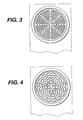
- FIG. 3 illustrates the top plan view of inner surface 13, in the maze configuration.
- Figure 4 illustrates the top plan view of inner surface 13, in the radial configuration.
- Figure 5 illustrates the top plan view of inner surface 13, in the cross hair design configuration.
- Figure 6 illustrates the bottom plan view of inner surface 13, in the logo configuration.
- Figure 6a illustrates the top plan view of inner surface 13, in the logo configuration.
- Figure 7 illustrates the top plan view of inner surface 13, in the spin wheel configuration.
- Figure 8 illustrates the top plan view of inner surface 13, in the ferris wheel configuration.
- Figure 9 illustrates the top plan view of inner surface 13, in the golf ball configuration.
- Figure 10 illustrates the top plan view of inner surface 13, in the sand dollar configuration.
- Figure 11 illustrated the top plan view of an enlarged portion of inner surface 13 of the maze configuration.
- representative raised portions 41 and recessed portions 43 are illustrated.
- the surface contact area of inner surfaces 13 surfaces may be calculated by the measuring the surface area of all raised portions and recessed portions of the inner surface.
- a method of hydrating a contact lens comprising, consisting essentially of, or consisting of hydrating said lens in a molded base wherein said molded base comprises a cavity formed in said molded base, wherein said cavity comprises an inner surface wherein said inner surface of said cavity has sufficient roughness so that a contact lens contained within said cavity floats freely in a solution.
- a method of hydrating a contact lens comprising, consisting essentially of, or consisting of hydrating said lens in a molded base wherein said molded base comprises a cavity formed in said molded base, wherein said cavity comprises an inner surface wherein the surface contact area of said inner surface is about 25 percent to about 70 percents of said inner surface.
- a molded base comprising, consisting essentially of, or consisting of a cavity formed in said molded base, wherein said cavity comprises an inner surface wherein said inner surface has sufficient roughness so that a medical device contained within said cavity floats freely in a solution.
- a molded base comprising, consisting essentially of, or consisting of, a cavity formed in said molded base wherein said cavity comprises an inner surface wherein the surface contact area of said inner surface is about 25 percent to about 75 percents of said inner surface.
- a method of making a molded base comprising a cavity formed in said molded base, wherein said cavity comprises an inner surface wherein said inner surface has sufficient roughness so that a medical device contained within said cavity floats freely in a solution, wherein the method comprises, consists essentially of, or consists of roughening the inner surface.
- roughening refers to methods of changing the texture of the inner surface which include but are not limited to glass bead blasting or EDM treatment.
- Nickel plated polished inserts were held in a rotating fixture. The fixture was rotated for a duration of 20 seconds at one revolution per second and sprayed from an angle of 30 degrees at a distance of 89 mm with glass beads (Cyclone Glass Bead, 60-100 G, R3893 medium) from a Cyclone 6.500 mm (diameter) nozzle.
- glass beads Cyclone Glass Bead, 60-100 G, R3893 medium
- To produce a light blast the pressure of the spray is set at 40 psi.
- the pressure is set at 60 psi.
- To produce a heavy blast the pressure is set at 80 psi.
- Polished nickel plated inserts were held in a fixture.
- the desired designs were produced using a CAD software system and exported to a computer system of a laser cutting machine.
- the insert was attached to a fixture of the laser cutting machine and the inserts were cut using that machine. After EDM treatment some inserts were glass bead blasted as well.
- These inserts were used to injection mold the base of several different contact lens packages from polypropylene (Exxon Achieve, PP1605, a metallocene polypropylene having a melt flow of 32 g/10 minutes, ASTM D-1238 (L).
Landscapes
- Chemical & Material Sciences (AREA)
- Composite Materials (AREA)
- Engineering & Computer Science (AREA)
- Mechanical Engineering (AREA)
- Eyeglasses (AREA)
- Purses, Travelling Bags, Baskets, Or Suitcases (AREA)
- Packaging Frangible Articles (AREA)
- Packages (AREA)
Description
- This invention relates to a package for storing a contact lens as well as a method of reducing the adherence of a contact lens to its package.
- Contact lenses have been used commercially to improve vision since the 1950s. At first contact lenses were made of hard materials, which were relatively easy to handle and package for use, but were uncomfortable for many patients. Later developments, gave rise to softer more comfortable lenses made of hydrophobic hydrogels, particularly silicone hydrogels. These lenses are very pliable, but due to this texture and their chemical composition, they present a number of problems with packaging.
- Most contact lenses are packaged in individual blister packages having a bowl portion and a foil top, where the bowl portion is made from a hydrophobic material such as polypropylene. See
U.S. Patent Nos. 4,691,820 ;5,054,610 ;5,337,888 ;5,375,698 ;5,409,104 ;5,515,964 ;5,609,246 ;5,695,049 ;5,697,495 ;5,704,468 ;5,711,416 ;5,722,536 ;5,573,108 ;5,823,327 ;5,704,468 ;5,983,608 ;6,029,808 ;6,044,966 ; and6,401,915 for examples of such packaging See alsoU.S. 2002/046958 A1 andEP O604 177 A -
-
Figure 1 illustrates the top plan view of a contact lens package. -
Figure 2 illustrates the side plan view of a contact lens package -
Figure 3 illustrates the top plan view the maze configuration. -
Figure 4 illustrates the top plan view of radial configuration. -
Figure 5 illustrates the top plan the cross hair design configuration. -
Figure 6a illustrates the top plan view of the logo configuration. -
Figure 6 illustrates the bottom plan view of the logo configuration. -
Figure 7 illustrates the top plan view of the spin wheel configuration. -
Figure 8 illustrates the top plan view of the ferris wheel configuration. -
Figure 9 illustrates the top plan view of the golf ball configuration. -
Figure 10 illustrates the top plan view of the sand dollar configuration. -
Figure 11 , illustrated the top plan view of an enlarged portion of inner surface of the maze configuration. - This invention includes a package for storing a contact lens in a solution as recited in the claims
- Further, the invention includes a method of reducing the adherence of a contact lens to its package as recite in the claims.
- As used herein a "medical device" is any device that is used to treat a human condition and is packaged in a solution. Examples of medical devices include but are not limited to ophthalmic devices that reside in or on the eye. Ophthalmic devices includes but are not limited to soft contact lenses, intraocular lenses, overlay lenses, ocular inserts, and optical inserts. These devices can provide optical correction or may be cosmetic. The preferred medical devices of the invention are soft contact lenses made from silicone elastomers or hydrogels, which include but are not limited to silicone hydrogels, and fluorohydrogels. Soft contact lens formulations are disclosed in
US Patent No. 5,710,302 ,WO 9421698 EP 406161 JP 2000016905 U.S. Pat. No. 5,998,498 ,US Pat. App. No. 09/532,943 U.S. Patent No. 6,087,415 ,U.S. Pat. No. 5,760,100 ,U.S. Pat. No.5,776 ,999 ,U.S. Pat. No. 5,789,461 ,U.S. Pat. No. 5,849,811 , andU.S. Pat. No. 5,965,631 . The particularly preferred medical devices of the invention are soft contact lenses made from etafilcon A, genfilcon A, lenefilcon A, polymacon, acquafilcon A, balafilcon A, lotrafilcon A. and silicone hydrogels as prepared inU.S. Pat. No. 5,998,498 ,US Pat. App. No. 09/532,943 US Pat App. No. 09/532,943, filed on August 30, 2000 U.S. Patent No. 6,087,415 ,U.S. Pat. No. 5,760,100 ,U.S. Pat. No.5,776 ,999 ,U.S. Pat. No. 5,789,461 ,U.S. Pat. No. 5,849,811 , andU.S. Pat. No. 5,965,631 . The most particularly preferred medical devices of the invention are soft contact lenses made acquafilcon A, balafilcon A,or lotrafilcon A. - The term "solution" refers to any liquid medium in which a medical device is stored. The preferred solutions are aqueous solutions contain physiological buffers. The particularly preferred solution is saline solution. The term "cavity" refers to an unfilled space suitable for holding a medical device and a solution. If the medical device is a soft contact lens shape of the cavity can be, but is not limited to the shape of the cavities in
U.S. Patent Nos. 4,691,820 ;5,054,610 ;5,337,888 ;5,375,698 ;5,409,104 ;5,467,868 ;5,515,964 ;5,609,246 ;5,695,049 ;5,697,495 ;5,704,468 ;5,711,416 ;5,722,536 ;5,573,108 ;5,823,327 ;5,704,468 ;5,983,608 ;6,029,808 ;6,044,966 ; and6,401,915 . The term "inner surface" refers to the surface of the cavity that is adjacent, but not adhering to the medical device. - The term "floats freely" refers to the physical interaction of the medical device with the molded base and the solution. A medical device floats freely in solution when the molded base filled with the device and the solution is rotated or jiggled in a manner where the solution is not spilled and the medical device contained therein, does not adhere to the inner surface of said molded base. For example if the medical device is a contact lens packaged with saline solution, the physical interaction of the contact lens with its packaging may be tested as follows. The flexible cover sheet is removed and the molded base is rotated or jiggled without spilling the saline solution while the contact lens is observed to determine if it is adhered to the inner surface of the molded base.
- The term "sufficient roughness" refers to the texture of the inner surface. Functionally, this surface must be rough enough so that a medical device immersed in a solution floats freely in said solution. For example, if the medical device is a contact lens immersed in a packing solution, particularly a silicone hydrogel contact lens, said lens floats freely in the packing solution.
- The degree of roughness can be expressed as the average roughness ("Ra," µm) which is measured by a number of machines which include but are not limited to Dimension 3000, manufactured by Digital Instruments, New View 200, manufatured by Zygo Corporation, and Form Talysurf Series Two, manufactured by Taylor Hobson Precision. The choice of machine is determined by the roughness of the surface. For example for surfaces having a surface roughness of ≤ 1.00 µm the Dimension 3000 may be used. For rougher surfaces, either the New View 200 or the Form Talysurf Series Two, may be used. Preferably, the Ra of the inner surface is about 0.2 µm to about 20. µm, more preferably, about 1.8 µm to about 4.5µm, even more preferably about 1.9 µm to about 2.1 µm, more preferably still about 0.3 µm to about 0.9 µm, even more preferably about 0.4 µm to about 0.9 µm, even more still, about 0.5 µm to about 0.8 µm, and most preferably about 0.6 µm.
- The molded base may be prepared from any number of materials provided that those materials are compatible with the inspection and sterilization requirements of device manufacture. Examples of suitable materials include but are not limited to polypropylene, polyethylene, nylons, olefin co-polymers, acrylics, rubbers, urethanes, polycarbonates, or fluorocarbons. The preferred materials are metallocenes polymers and co-polymers made of polypropylene, polyethylene, having a melt flow range of about 15 g/10 minutes to about 44 g/10 minutes as determined by ASTM D-1238. The molded base is formed by any of a number of methods, which include but are not limited to injection molding, where the surface of the metal tool that is used to form the molded base is roughened by glass bead blasting or electron discharge machining ("EDM") to serve as a template for the roughened inner surface.
- The "flexible cover sheet" can be an adhesive laminate of an aluminum foil and a polypropylene film or any other extruded or co-extruded film that can be sealed to the top surface of the flange in order to form a hermetic seal for the medical device and the solution. The flexible cover need not be completely sealed to the entire top surface of the flange and preferably the flexible cover sheet is sealed an area of the flange that is in close proximity to the cavity. Further the flexible cover sheet need not cover the entire top surface of said molded base. As used herein, the term "forming" refers to all suitable methods of preparing of preparing the molded base, including but not limited to injection molding and thermal molding. The preferred method of forming the molded base is injection molding.
- As used herein the term "surface contact area" refers to the portion of the inner surface that can have physical contact with, but does not adhere to the medical device. Due to fact that the medical device floats freely in the packaging, the inner surface may have areas that are not in contact with the medical device at all times, particularly when the package is rotated. Therefore, the surface contact area is measured as a percentage of total inner surface that can have contact with the medical device, at any time. The preferred surface contact area is about 33 to about 65 percent of the inner surface.
-
Figure 1 illustrates the top plan view of one embodiment of the invention, a contact lens package. Moldedbase 10, having arectangular flange 22, having atop surface 20 andinner surface 13, is shown. The flexible cover sheet 40 (not shown) is detachably attached totop surface 20 at the raisedannular sealing area 14.Figure 2 illustrates the side plan view of the package having cavity , flexible cover sheet 40 (shown half pulled back), the packaged contact lens, 17 andsolution 18. -
Inner surface 13 is be roughed with glass bead blasting, EDM or other treatments. For example in order to produce an inner surface having an Ra of about 1.0 µm to about 2.0 µm, the tools that are used to form the molds are glass bead blasted on the appropriate surface. For example in order to produce an inner surface having an Ra of about 1.0 µM, the tool is blasted at a pressure of about 40 to about 60 psi for about 20 secs. To produce an inner surface having an Ra of about 2.0 µm, the tool is blasted at a pressure of about 60 to about 80 psi for about 20 secs. In order to produce inner surfaces having an Ra 19 µm, a design is etched on the appropriate surface of the tool using EDM and the same surface is treated glass bead blasted at about 40 to about 60 psi. - In order to produce an inner surface having a surface contact area of about 30 percent to about 70 percent, a design is formed on the tool's appropriate surface using EDM. A number of different designs for
inner surface 13 are illustrated in the following figures.Figure 3 illustrates the top plan view ofinner surface 13, in the maze configuration.Figure 4 illustrates the top plan view ofinner surface 13, in the radial configuration.Figure 5 illustrates the top plan view ofinner surface 13, in the cross hair design configuration.Figure 6 illustrates the bottom plan view ofinner surface 13, in the logo configuration.Figure 6a illustrates the top plan view ofinner surface 13, in the logo configuration.Figure 7 illustrates the top plan view ofinner surface 13, in the spin wheel configuration.Figure 8 illustrates the top plan view ofinner surface 13, in the ferris wheel configuration.Figure 9 illustrates the top plan view ofinner surface 13, in the golf ball configuration.Figure 10 illustrates the top plan view ofinner surface 13, in the sand dollar configuration.Figure 11 , illustrated the top plan view of an enlarged portion ofinner surface 13 of the maze configuration. In this figure representative raisedportions 41 and recessedportions 43 are illustrated. The surface contact area ofinner surfaces 13 surfaces may be calculated by the measuring the surface area of all raised portions and recessed portions of the inner surface. - When soft contact lenses are prepared the lenses cured to a hard disc and subsequently hydrated with water to give the non-sterilized final product.
- During this hydration step, soft contact lenses often stick to the surface of the hydration chamber and it would be useful to find a method of hydrating soft contact lenses which alleviates this problem.
- To solve this problem, there is disclosed a method of hydrating a contact lens comprising, consisting essentially of, or consisting of hydrating said lens in a molded base wherein said molded base comprises a cavity formed in said molded base, wherein said cavity comprises an inner surface wherein said inner surface of said cavity has sufficient roughness so that a contact lens contained within said cavity floats freely in a solution.
- Further, there is disclosed a method of hydrating a contact lens comprising, consisting essentially of, or consisting of hydrating said lens in a molded base wherein said molded base comprises a cavity formed in said molded base, wherein said cavity comprises an inner surface wherein the surface contact area of said inner surface is about 25 percent to about 70 percents of said inner surface.
- Still further, there is disclosed a molded base comprising, consisting essentially of, or consisting of a cavity formed in said molded base, wherein said cavity comprises an inner surface wherein said inner surface has sufficient roughness so that a medical device contained within said cavity floats freely in a solution.
- Yet still further, there is disclosed a molded base comprising, consisting essentially of, or consisting of, a cavity formed in said molded base wherein said cavity comprises an inner surface wherein the surface contact area of said inner surface is about 25 percent to about 75 percents of said inner surface.
- Even yet still further, there is disclosed a method of making a molded base comprising a cavity formed in said molded base, wherein said cavity comprises an inner surface wherein said inner surface has sufficient roughness so that a medical device contained within said cavity floats freely in a solution, , wherein the method comprises, consists essentially of, or consists of roughening the inner surface. As used herein, the term "roughening" refers to methods of changing the texture of the inner surface which include but are not limited to glass bead blasting or EDM treatment.
- The following examples are included.
- Nickel plated polished inserts were held in a rotating fixture. The fixture was rotated for a duration of 20 seconds at one revolution per second and sprayed from an angle of 30 degrees at a distance of 89 mm with glass beads (Cyclone Glass Bead, 60-100 G, R3893 medium) from a Cyclone 6.500 mm (diameter) nozzle. To produce a light blast the pressure of the spray is set at 40 psi. To produce a medium blast, the pressure is set at 60 psi. To produce a heavy blast, the pressure is set at 80 psi. These inserts were used to injection mold the base of several different contact lens packages from polypropylene (Exxon Achieve, PP1605, a metallocene polypropylene having a melt flow of 32 g/10 minutes, ASTM D-1238 (L). If the required degree of roughness was not obtained after one roughening procedure, the inserts were roughened again.
- Polished nickel plated inserts were held in a fixture. The desired designs were produced using a CAD software system and exported to a computer system of a laser cutting machine. The insert was attached to a fixture of the laser cutting machine and the inserts were cut using that machine. After EDM treatment some inserts were glass bead blasted as well. These inserts were used to injection mold the base of several different contact lens packages from polypropylene (Exxon Achieve, PP1605, a metallocene polypropylene having a melt flow of 32 g/10 minutes, ASTM D-1238 (L).
- Contact lenses made from acquafilcon A, a silicone hydrogel, were added to individual polypropylene blister packs having different inner surfaces containing 950µL of saline solution and then the blister pack was heat sealed. Lenses were visually evaluated for lens' adhesion to the package after sterilization. The design of the package, the Ra number (µm), percentage of surface contact area, the number of lenses that stuck to the package, and number of lenses that were free floating is displayed in Table 1.
TABLE 1 percent surface Inner Surface Ra, µm contact area # lenses tested # stuck control 0.139 100 84 84 light blast 0.549 N/A 12 4 medium blast 1.038 N/A 60 2 heavy blast 1.912 N/A 60 0 maze N/A 65 60 0 cross hair N/A N/A 12 8 spin wheel N/A N/A 12 8 ferris wheel N/A 2 12 12 sand dollar N/A 11 12 11 golf ball N/A 16 12 9 logo design N/A N/A 12 12 radial design N/A 33 60 1 maze with medium blast 19.1 N/A 60 0 cross hair with medium blast N/A N/A 60 0 ferris wheel with medium blast N/A N/A 80 0 logo with medium blast N/A N/A 60 2 - This table illustrates the ability of a roughened inner surface to prevent adherence of the lens to its package. The term "N/A" means not available.
Claims (10)
- A package for storing a contact lens (17) in a solution (18) comprising(a) a molded base (10) comprising
a cavity formed in said molded base (10) wherein said cavity comprises an inner surface (13), and
a flange (22) extending outwardly from the periphery of said cavity wherein said flange (22) comprises a top surface (20);
wherein the base (10) is molded such that the inner surface (13) of the cavity includes a design comprising a configuration of raised portions (41) having a surface contact area defined as the measured surface area of all the raised portions (41) within the cavity such that a contact lens (17) disposed in the cavity can contact about 25 percent to about 75 percent of said inner surface (13),(b) a flexible cover sheet (40) superimposed over said top surface (22) of said flange (20) and detachably sealed to said flange (20) at about the periphery of said cavity to form an enclosure between said inner surface (13) and said flexible cover (40), wherein said surface contact area of said inner surface (13) is about 25 percent to about 75 percent of said inner surface (13) and wherein said contact lens (17) floats freely in a solution (18), and wherein the sufaces of the raised portions are roughened. - The package of claim 1 wherein the inner surface (13) has an average roughness of about 1.0µm to about 20µm.
- The package of claim 1 wherein the inner surface (13) has an average roughness of about 1.8µm to about 4.5µm.
- The package of claim 1 wherein the inner surface (13) has an average roughness of about 1.9µm to about 2.1 µm.
- The package of claim 1 wherein the surface contact area of said inner surface (13) is about 33 to about 65 percent.
- A method of reducing the adherence of a contact lens (17) to its package comprising storing said contact lens (17) in a solution (18) in a package comprising,(a) a molded base (10) comprising
a cavity formed in said molded base (10) wherein said cavity comprises an inner surface (13), and
a flange (20) extending outwardly from the periphery of said cavity wherein said flange (20) comprises a top surface (22);
wherein the base (10) is molded such that the inner surface (13) of the cavity includes a design comprising a configuration of raised portions (41) having a surface contact area defined as the measured surface area of all the raised portions (41) within the cavity such that a contact lens (17) disposed in the cavity can contact about 25 percent to about 75 percent of said inner surface (13);(b) a flexible cover sheet (40) superimposed over said top surface (22) of said flange (20) and detachably sealed to said flange (20) at about the periphery of said cavity to form an enclosure between said inner surface (13) and said flexible cover (40), wherein said surface contact area of said inner surface (13) is about 25 percent to about 75 percent of said inner surface (13) and wherein said contact lens (17) floats freely in a solution (18), and wherein the surfaces of the raised portions are roughened - The method of claim 6, wherein the inner surface (13) has an average roughness of about 1.0µm to about 20µm.
- The method of claim 6 wherein the inner surface (13) has an average roughness of about 1.8µm to about 4.5µm.
- The method of claim 6 wherein the inner surface (13) has an average roughness of about 1.9µm to about 2.1 µm.
- The method of claim 6 wherein the surface contact area of said inner surface (13) is about 33 to about 65 percent.
Applications Claiming Priority (3)
| Application Number | Priority Date | Filing Date | Title |
|---|---|---|---|
| US183133 | 1980-09-02 | ||
| US10/183,133 US20040004008A1 (en) | 2002-06-26 | 2002-06-26 | Contact lens packages |
| PCT/US2003/019347 WO2004002849A1 (en) | 2002-06-26 | 2003-06-18 | Contact lens packages |
Publications (2)
| Publication Number | Publication Date |
|---|---|
| EP1525141A1 EP1525141A1 (en) | 2005-04-27 |
| EP1525141B1 true EP1525141B1 (en) | 2013-08-14 |
Family
ID=29999197
Family Applications (1)
| Application Number | Title | Priority Date | Filing Date |
|---|---|---|---|
| EP03739210.7A Expired - Lifetime EP1525141B1 (en) | 2002-06-26 | 2003-06-18 | Contact lens package and method for reducing the adherence of a contact lens to its package |
Country Status (11)
| Country | Link |
|---|---|
| US (6) | US20040004008A1 (en) |
| EP (1) | EP1525141B1 (en) |
| JP (1) | JP2005530657A (en) |
| KR (1) | KR20050058290A (en) |
| CN (1) | CN1665726B (en) |
| AR (1) | AR041792A1 (en) |
| AU (1) | AU2003245582A1 (en) |
| BR (1) | BR0312050A (en) |
| CA (1) | CA2489680A1 (en) |
| TW (1) | TW200404528A (en) |
| WO (1) | WO2004002849A1 (en) |
Families Citing this family (39)
| Publication number | Priority date | Publication date | Assignee | Title |
|---|---|---|---|---|
| CN1980582B (en) * | 2001-08-17 | 2010-12-22 | 美你康株式会社 | Package for disposable soft contact lenses |
| US7086526B2 (en) | 2001-08-17 | 2006-08-08 | Clearlab International Pte Ltd. | Packaging for disposable soft contact lenses |
| US20040004008A1 (en) | 2002-06-26 | 2004-01-08 | Peck James M. | Contact lens packages |
| US7832552B2 (en) | 2002-08-17 | 2010-11-16 | Menicon Co. Ltd. | Duo packaging for disposable soft contact lenses using a substrate |
| EP2281584A1 (en) * | 2002-12-23 | 2011-02-09 | Johnson and Johnson Vision Care, Inc. | Contact lens packages containing additives |
| USD520236S1 (en) * | 2004-01-09 | 2006-05-09 | Menicon Co., Ltd. | Portion of a contact lens container for use in a refrigerator |
| US7275640B2 (en) * | 2004-02-05 | 2007-10-02 | Boston Scientific Scimed, Inc. | Packaging for imparting anti-microbial properties to a medical device |
| US20050194391A1 (en) * | 2004-03-04 | 2005-09-08 | Medtronic, Inc. | Medical device and information container |
| USD511893S1 (en) * | 2004-05-04 | 2005-11-29 | St. Shine Optical Co., Ltd. | Package for contact lenses |
| USD512217S1 (en) * | 2004-05-04 | 2005-12-06 | St. Shine Optical Co., Ltd. | Package for contact lenses |
| USD520867S1 (en) * | 2004-05-04 | 2006-05-16 | St. Shine Optical Co., Ltd. | Package for contact lenses |
| US7426993B2 (en) * | 2005-08-09 | 2008-09-23 | Coopervision International Holding Company, Lp | Contact lens package |
| US7799249B2 (en) * | 2005-08-09 | 2010-09-21 | Coopervision International Holding Company, Lp | Systems and methods for producing silicone hydrogel contact lenses |
| US20070074980A1 (en) * | 2005-09-02 | 2007-04-05 | Bankoski Brian R | Implant rehydration packages and methods of use |
| US20070149428A1 (en) * | 2005-12-14 | 2007-06-28 | Bausch & Lomb Incorporated | Method of Packaging a Lens |
| DE102006051366A1 (en) * | 2006-10-27 | 2008-05-08 | Boehringer Ingelheim Pharma Gmbh & Co. Kg | Method for sterilizing a film container |
| US20090145086A1 (en) * | 2007-12-11 | 2009-06-11 | Reynolds Ger M | Method for treating ophthalmic lenses |
| US20090145091A1 (en) * | 2007-12-11 | 2009-06-11 | Richard Connolly | Method for treating ophthalmic lenses |
| US8070475B2 (en) * | 2007-12-31 | 2011-12-06 | Bausch & Lomb Incorporated | Casting mold for forming a biomedical device including an ophthalmic device |
| JP4491514B1 (en) * | 2008-10-21 | 2010-06-30 | 株式会社メニコン | Contact lens storage container |
| WO2010077919A1 (en) | 2008-12-31 | 2010-07-08 | Johnson & Johnson Vision Care, Inc. | An apparatus and method for distributing ophthalmic lenses |
| US9296160B2 (en) * | 2009-09-11 | 2016-03-29 | Coopervision International Holding Company, Lp | Method for moving wet ophthalmic lenses during their manufacture |
| SG170635A1 (en) * | 2009-10-22 | 2011-05-30 | Novartis Ag | Contact lens package with micro-textured interior bowl surface |
| SG189572A1 (en) * | 2011-10-18 | 2013-05-31 | Menicon Singapore Pte Ltd | Systems and methods for multi-stage sealing of contact lens packaging |
| SG189576A1 (en) * | 2011-10-18 | 2013-05-31 | Menicon Singapore Pte Ltd | Packaging for disposable soft contact lenses having pre-formed multi-layer structural laminate |
| KR20130069041A (en) * | 2011-12-16 | 2013-06-26 | 삼성전자주식회사 | Display apparatus and method |
| US20180134475A1 (en) * | 2012-10-18 | 2018-05-17 | Menicon Singapore Pte Ltd. | Systems and Methods for Multi-Stage Sealing of Contact Lens Packaging |
| WO2015186640A1 (en) * | 2014-06-05 | 2015-12-10 | 共同印刷株式会社 | Laminate for use in blister pack, blister pack using same, and blister pack packaging |
| USD755517S1 (en) * | 2014-10-15 | 2016-05-10 | Ronnie Shugar | Contact lens case |
| ES2575133B1 (en) * | 2014-12-23 | 2017-02-08 | Disop, S.A. | Contact holders for cleaning them |
| USD781157S1 (en) * | 2015-12-16 | 2017-03-14 | Johnson & Johnson Consumer Inc. | Pharmaceutical package |
| KR101975160B1 (en) * | 2016-02-29 | 2019-05-03 | 쿠퍼비젼 인터내셔날 홀딩 캄파니, 엘피 | Contact lens blister pack label and blister pack bonding method |
| US9655423B1 (en) * | 2016-04-28 | 2017-05-23 | Hon Hai Precision Industry Co., Ltd. | Contact lens package |
| USD827425S1 (en) * | 2016-08-10 | 2018-09-04 | Da Bomb, Llc | Bath Product Packaging |
| USD1000270S1 (en) * | 2021-05-07 | 2023-10-03 | YFY Consumer Products, Co. | Pod blister package |
| USD1045993S1 (en) * | 2022-01-25 | 2024-10-08 | Americhip Inc. | Advertising display |
| GB2629533A (en) * | 2022-06-17 | 2024-10-30 | Pegavision Corp | Contact lens product as well as packaging case thereof and test method therefor |
| TWI875498B (en) * | 2024-03-01 | 2025-03-01 | 昱嘉科技股份有限公司 | Packaging box for easy removal and improved surface quality of contact lenses |
| WO2025192612A1 (en) * | 2024-03-12 | 2025-09-18 | Menicon Co., Ltd. | Blister package for contact lenses |
Family Cites Families (61)
| Publication number | Priority date | Publication date | Assignee | Title |
|---|---|---|---|---|
| US3279482A (en) * | 1964-12-09 | 1966-10-18 | Barnes Hind International Inc | Lens washing machine |
| US3394717A (en) * | 1966-09-20 | 1968-07-30 | Richard G. Hollinger | Contact lens container |
| JPS5641534Y2 (en) * | 1976-08-09 | 1981-09-29 | ||
| US4129211A (en) * | 1976-09-07 | 1978-12-12 | Monsanto Company | Wafer packaging system |
| US4691820A (en) * | 1985-11-18 | 1987-09-08 | Vistakon, Inc. | Package for hydrophilic contact lens |
| AU587875B2 (en) * | 1985-11-18 | 1989-08-31 | Vistakon, Inc. | Package for hydrophylic contact lens |
| US4858754A (en) * | 1988-06-07 | 1989-08-22 | Ryder International Corporation | Molding apparatus and construction of contact lens case |
| US5084393A (en) * | 1988-09-01 | 1992-01-28 | Alena Rogalsky | Container for a biological culture |
| US5573108A (en) * | 1988-11-02 | 1996-11-12 | British Technology Group Ltd. | Disposable contact lens package |
| US5054610A (en) * | 1989-05-31 | 1991-10-08 | Ciba-Geigy Corporation | Disposable single-use contact lens conditioning package |
| US5115056A (en) | 1989-06-20 | 1992-05-19 | Ciba-Geigy Corporation | Fluorine and/or silicone containing poly(alkylene-oxide)-block copolymers and contact lenses thereof |
| US4949959A (en) * | 1989-10-10 | 1990-08-21 | Stevens William E | Barbell assist device |
| US4942959A (en) * | 1989-10-23 | 1990-07-24 | Sauber Charles J | Buoyant structures in contact lens case |
| US5080839A (en) | 1990-04-17 | 1992-01-14 | Johnson & Johnson Vision Products, Inc. | Process for hydrating soft contact lenses |
| US5130011A (en) * | 1991-09-19 | 1992-07-14 | Sage Jr James R | Contact lens holder |
| JPH06205706A (en) * | 1992-12-09 | 1994-07-26 | Ciba Geigy Ag | Contact lens case |
| NZ250453A (en) * | 1992-12-21 | 1996-12-20 | Johnson & Johnson Vision Prod | Ophthalmic lens package; planar surface with concave bowl for containing lens, sealing sheet covering bowl with lens therein |
| US5326505A (en) * | 1992-12-21 | 1994-07-05 | Johnson & Johnson Vision Products, Inc. | Method for treating an ophthalmic lens mold |
| US5374662A (en) | 1993-03-15 | 1994-12-20 | Bausch & Lomb Incorporated | Fumarate and fumaramide siloxane hydrogel compositions |
| US5375698A (en) * | 1993-05-07 | 1994-12-27 | Allergan, Inc. | Prefilled, resealable contact lens container |
| US5337888A (en) * | 1993-09-01 | 1994-08-16 | Morrison Robert J | Contact lens case |
| US5697495A (en) * | 1993-11-02 | 1997-12-16 | Johnson & Johnson Vision Products, Inc. | Packaging arrangement for contact lenses |
| US5823327A (en) * | 1993-11-02 | 1998-10-20 | Johnson & Johnson Vision Products, Inc. | Packaging arrangement for contact lenses |
| TW295570B (en) * | 1994-05-04 | 1997-01-11 | Ciba Geigy Ag | |
| US5409104A (en) * | 1994-06-01 | 1995-04-25 | Ciba-Geigy Corporation | Contact lens package having improved access features |
| US5578331A (en) * | 1994-06-10 | 1996-11-26 | Vision Products, Inc. | Automated apparatus for preparing contact lenses for inspection and packaging |
| US5706634A (en) * | 1994-06-10 | 1998-01-13 | Johnson & Johnson Vision Products, Inc. | Contact lens transfer device |
| US5711416A (en) * | 1994-06-15 | 1998-01-27 | Bauman; Robert C. | Disposable contact lens storage container with concave storage recess |
| US5760100B1 (en) * | 1994-09-06 | 2000-11-14 | Ciba Vision Corp | Extended wear ophthalmic lens |
| US5524419A (en) * | 1995-02-02 | 1996-06-11 | Bausch & Lomb Incorporated | Method and apparatus for molding contact lenses and making their container |
| TW585882B (en) * | 1995-04-04 | 2004-05-01 | Novartis Ag | A method of using a contact lens as an extended wear lens and a method of screening an ophthalmic lens for utility as an extended-wear lens |
| US5515964A (en) * | 1995-04-13 | 1996-05-14 | Bauman; Robert C. | Contact lens package with lens retaining recess |
| US5704468A (en) * | 1995-09-29 | 1998-01-06 | Johnson & Johnson Vision Products, Inc. | Packaging arrangement for contact lenses |
| ES2164265T3 (en) * | 1995-12-07 | 2002-02-16 | Bausch & Lomb | USEFUL MONOMERIC UNITS TO REDUCE THE SILICONE HYDROGEL MODULE. |
| US5722536A (en) * | 1996-02-08 | 1998-03-03 | Bausch & Lomb Incorporated | Disposable contact lens package with snap-together feature |
| US5695049A (en) * | 1996-10-10 | 1997-12-09 | Johnson & Johnson Vision Products, Inc. | Contact lens package with insertion feature |
| GB9624159D0 (en) * | 1996-11-20 | 1997-01-08 | Roseshaw Productions Limited | Improvements in or relating to contact lens cases and use thereof |
| US5972292A (en) * | 1997-04-16 | 1999-10-26 | Bausch & Lomb Incorporated | Sealing and venting system for oxidative disinfection of contact lenses |
| EP0887282A1 (en) * | 1997-06-25 | 1998-12-30 | Wöhlk Contact-Linsen GmbH | Ready-for-sale container for the transport of contact lenses and contact lens provided for this container |
| GB9716118D0 (en) * | 1997-07-30 | 1997-10-08 | Ocular Sciences Limited | Container |
| DK0999767T3 (en) * | 1997-07-30 | 2001-11-19 | Stefan Umdasch Design Kg | Container for storing contact lenses |
| AU9531598A (en) * | 1997-10-14 | 1999-05-17 | Thomas Faxe | A package with an applicator for a contact lens |
| EP1035784A1 (en) * | 1997-12-01 | 2000-09-20 | Novartis AG | Contact lens storage container |
| US5998498A (en) * | 1998-03-02 | 1999-12-07 | Johnson & Johnson Vision Products, Inc. | Soft contact lenses |
| US6087415A (en) * | 1998-06-11 | 2000-07-11 | Johnson & Johnson Vision Care, Inc. | Biomedical devices with hydrophilic coatings |
| JP2000016905A (en) | 1998-07-01 | 2000-01-18 | Tokuriki Kagaku Kenkyusho:Kk | Antibacterial-fungal agent and antibacterial-fungal material |
| US6244430B1 (en) * | 1998-10-26 | 2001-06-12 | Aaron T. Travis | Easily transported contact lens care kit |
| US6050398A (en) * | 1998-11-25 | 2000-04-18 | Novartis, Ag | Contact lens storage container |
| US6042230A (en) * | 1998-12-14 | 2000-03-28 | Johnson & Johnson Vision Products, Inc. | Markings for contact lenses |
| US6082533A (en) * | 1998-12-15 | 2000-07-04 | Bausch & Lomb Incorporated | Contact lens package |
| US6029808A (en) * | 1999-01-29 | 2000-02-29 | Johnson & Johnson Vision Products, Inc. | Primary package for contact lens |
| US6474465B1 (en) * | 1999-11-19 | 2002-11-05 | Novartis Ag | Blister package |
| US6368522B1 (en) * | 2000-01-03 | 2002-04-09 | Johnson & Johnson Vision Care, Inc. | Mold for forming a contact lens and method of preventing formation of small strands of contact lens material during contact lens manufacture |
| US7374037B2 (en) * | 2000-09-01 | 2008-05-20 | Novartis Ag | Textured contact lens package |
| US6531432B2 (en) * | 2000-12-07 | 2003-03-11 | Johnson & Johnson Vision Care, Inc. | Contact lens packaging solutions |
| US7086526B2 (en) * | 2001-08-17 | 2006-08-08 | Clearlab International Pte Ltd. | Packaging for disposable soft contact lenses |
| GB0126708D0 (en) * | 2001-11-07 | 2002-01-02 | Provis Ltd | Packaging for contact lenses |
| US20040004008A1 (en) * | 2002-06-26 | 2004-01-08 | Peck James M. | Contact lens packages |
| US20040214914A1 (en) * | 2003-04-24 | 2004-10-28 | Ocular Sciences, Inc. | Hydrogel contact lenses and package systems and production methods for same |
| US7811503B2 (en) * | 2007-04-18 | 2010-10-12 | Coopervision International Holding Company, Lp | Devices, assemblies, and methods for extracting extractable materials from polymerized biomedical devices |
| US20090145091A1 (en) * | 2007-12-11 | 2009-06-11 | Richard Connolly | Method for treating ophthalmic lenses |
-
2002
- 2002-06-26 US US10/183,133 patent/US20040004008A1/en not_active Abandoned
-
2003
- 2003-06-10 US US10/458,439 patent/US20040031701A1/en not_active Abandoned
- 2003-06-18 EP EP03739210.7A patent/EP1525141B1/en not_active Expired - Lifetime
- 2003-06-18 JP JP2004517686A patent/JP2005530657A/en active Pending
- 2003-06-18 KR KR1020047020996A patent/KR20050058290A/en not_active Ceased
- 2003-06-18 CA CA002489680A patent/CA2489680A1/en not_active Abandoned
- 2003-06-18 CN CN03815191XA patent/CN1665726B/en not_active Expired - Lifetime
- 2003-06-18 BR BR0312050-3A patent/BR0312050A/en not_active Application Discontinuation
- 2003-06-18 AU AU2003245582A patent/AU2003245582A1/en not_active Abandoned
- 2003-06-18 WO PCT/US2003/019347 patent/WO2004002849A1/en not_active Ceased
- 2003-06-25 TW TW092117195A patent/TW200404528A/en unknown
- 2003-06-26 AR ARP030102300A patent/AR041792A1/en unknown
-
2007
- 2007-10-30 US US11/927,819 patent/US20080105569A1/en not_active Abandoned
- 2007-11-09 US US11/937,780 patent/US20080060950A1/en not_active Abandoned
-
2010
- 2010-10-04 US US12/897,005 patent/US20110018152A1/en not_active Abandoned
-
2012
- 2012-07-02 US US13/540,086 patent/US9585450B2/en not_active Expired - Lifetime
Also Published As
| Publication number | Publication date |
|---|---|
| HK1075236A1 (en) | 2005-12-09 |
| JP2005530657A (en) | 2005-10-13 |
| BR0312050A (en) | 2005-03-29 |
| US20040004008A1 (en) | 2004-01-08 |
| KR20050058290A (en) | 2005-06-16 |
| AU2003245582A1 (en) | 2004-01-19 |
| US9585450B2 (en) | 2017-03-07 |
| US20080105569A1 (en) | 2008-05-08 |
| CN1665726B (en) | 2010-05-26 |
| WO2004002849A1 (en) | 2004-01-08 |
| CA2489680A1 (en) | 2004-01-08 |
| US20120267808A1 (en) | 2012-10-25 |
| US20040031701A1 (en) | 2004-02-19 |
| CN1665726A (en) | 2005-09-07 |
| US20110018152A1 (en) | 2011-01-27 |
| EP1525141A1 (en) | 2005-04-27 |
| AR041792A1 (en) | 2005-06-01 |
| US20080060950A1 (en) | 2008-03-13 |
| TW200404528A (en) | 2004-04-01 |
Similar Documents
| Publication | Publication Date | Title |
|---|---|---|
| US9585450B2 (en) | Contact lens packages | |
| EP1441962B1 (en) | Packaging for contact lenses | |
| EP2935016B1 (en) | Contact lens package | |
| US8281920B2 (en) | Contact lens packages | |
| US10390593B2 (en) | Contact lens blister packages | |
| EP1667911B1 (en) | Method and container for sterilizing and storing soft contact lenses | |
| US20080230403A1 (en) | Textured contact lens package | |
| TWI801970B (en) | Dimpled contact lens, mold for cast molding of contact lens, injection molding insert for forming mold for cast molding of contact lens, method of administering beneficial agent to ocular surface of subject | |
| JP2005530657A5 (en) | ||
| HK1075236B (en) | Contact lens package and method for reducing the adherence of a contact lens to its package | |
| KR20240124978A (en) | Pressurized or vacuum sealed contact lens packages | |
| TW202539967A (en) | Contact lens packages and methods of opening |
Legal Events
| Date | Code | Title | Description |
|---|---|---|---|
| PUAI | Public reference made under article 153(3) epc to a published international application that has entered the european phase |
Free format text: ORIGINAL CODE: 0009012 |
|
| 17P | Request for examination filed |
Effective date: 20050110 |
|
| AK | Designated contracting states |
Kind code of ref document: A1 Designated state(s): AT BE BG CH CY CZ DE DK EE ES FI FR GB GR HU IE IT LI LU MC NL PT RO SE SI SK TR |
|
| AX | Request for extension of the european patent |
Extension state: AL LT LV MK |
|
| DAX | Request for extension of the european patent (deleted) | ||
| RBV | Designated contracting states (corrected) |
Designated state(s): DE FR GB IE IT |
|
| REG | Reference to a national code |
Ref country code: HK Ref legal event code: DE Ref document number: 1075236 Country of ref document: HK |
|
| 17Q | First examination report despatched |
Effective date: 20070323 |
|
| GRAP | Despatch of communication of intention to grant a patent |
Free format text: ORIGINAL CODE: EPIDOSNIGR1 |
|
| GRAS | Grant fee paid |
Free format text: ORIGINAL CODE: EPIDOSNIGR3 |
|
| GRAA | (expected) grant |
Free format text: ORIGINAL CODE: 0009210 |
|
| AK | Designated contracting states |
Kind code of ref document: B1 Designated state(s): DE FR GB IE IT |
|
| REG | Reference to a national code |
Ref country code: GB Ref legal event code: FG4D |
|
| REG | Reference to a national code |
Ref country code: IE Ref legal event code: FG4D |
|
| REG | Reference to a national code |
Ref country code: DE Ref legal event code: R096 Ref document number: 60344732 Country of ref document: DE Effective date: 20131010 |
|
| REG | Reference to a national code |
Ref country code: HK Ref legal event code: GR Ref document number: 1075236 Country of ref document: HK |
|
| PLBE | No opposition filed within time limit |
Free format text: ORIGINAL CODE: 0009261 |
|
| STAA | Information on the status of an ep patent application or granted ep patent |
Free format text: STATUS: NO OPPOSITION FILED WITHIN TIME LIMIT |
|
| 26N | No opposition filed |
Effective date: 20140515 |
|
| REG | Reference to a national code |
Ref country code: DE Ref legal event code: R097 Ref document number: 60344732 Country of ref document: DE Effective date: 20140515 |
|
| REG | Reference to a national code |
Ref country code: FR Ref legal event code: PLFP Year of fee payment: 14 |
|
| REG | Reference to a national code |
Ref country code: FR Ref legal event code: PLFP Year of fee payment: 15 |
|
| REG | Reference to a national code |
Ref country code: FR Ref legal event code: PLFP Year of fee payment: 16 |
|
| PGFP | Annual fee paid to national office [announced via postgrant information from national office to epo] |
Ref country code: IT Payment date: 20220510 Year of fee payment: 20 Ref country code: IE Payment date: 20220510 Year of fee payment: 20 Ref country code: GB Payment date: 20220428 Year of fee payment: 20 Ref country code: FR Payment date: 20220510 Year of fee payment: 20 Ref country code: DE Payment date: 20220505 Year of fee payment: 20 |
|
| REG | Reference to a national code |
Ref country code: DE Ref legal event code: R071 Ref document number: 60344732 Country of ref document: DE |
|
| REG | Reference to a national code |
Ref country code: GB Ref legal event code: PE20 Expiry date: 20230617 |
|
| REG | Reference to a national code |
Ref country code: IE Ref legal event code: MK9A |
|
| PG25 | Lapsed in a contracting state [announced via postgrant information from national office to epo] |
Ref country code: IE Free format text: LAPSE BECAUSE OF EXPIRATION OF PROTECTION Effective date: 20230618 Ref country code: GB Free format text: LAPSE BECAUSE OF EXPIRATION OF PROTECTION Effective date: 20230617 |