EP1524770A2 - Method and apparatus for transmitting digital audio signals - Google Patents
Method and apparatus for transmitting digital audio signals Download PDFInfo
- Publication number
- EP1524770A2 EP1524770A2 EP04017519A EP04017519A EP1524770A2 EP 1524770 A2 EP1524770 A2 EP 1524770A2 EP 04017519 A EP04017519 A EP 04017519A EP 04017519 A EP04017519 A EP 04017519A EP 1524770 A2 EP1524770 A2 EP 1524770A2
- Authority
- EP
- European Patent Office
- Prior art keywords
- audio
- data
- format
- information segments
- line
- Prior art date
- Legal status (The legal status is an assumption and is not a legal conclusion. Google has not performed a legal analysis and makes no representation as to the accuracy of the status listed.)
- Withdrawn
Links
Images



Classifications
-
- H—ELECTRICITY
- H04—ELECTRIC COMMUNICATION TECHNIQUE
- H04N—PICTORIAL COMMUNICATION, e.g. TELEVISION
- H04N21/00—Selective content distribution, e.g. interactive television or video on demand [VOD]
- H04N21/40—Client devices specifically adapted for the reception of or interaction with content, e.g. set-top-box [STB]; Operations thereof
- H04N21/41—Structure of client; Structure of client peripherals
- H04N21/426—Internal components of the client ; Characteristics thereof
- H04N21/42607—Internal components of the client ; Characteristics thereof for processing the incoming bitstream
- H04N21/4263—Internal components of the client ; Characteristics thereof for processing the incoming bitstream involving specific tuning arrangements, e.g. two tuners
-
- H—ELECTRICITY
- H04—ELECTRIC COMMUNICATION TECHNIQUE
- H04N—PICTORIAL COMMUNICATION, e.g. TELEVISION
- H04N21/00—Selective content distribution, e.g. interactive television or video on demand [VOD]
- H04N21/40—Client devices specifically adapted for the reception of or interaction with content, e.g. set-top-box [STB]; Operations thereof
- H04N21/41—Structure of client; Structure of client peripherals
- H04N21/426—Internal components of the client ; Characteristics thereof
-
- H—ELECTRICITY
- H04—ELECTRIC COMMUNICATION TECHNIQUE
- H04N—PICTORIAL COMMUNICATION, e.g. TELEVISION
- H04N5/00—Details of television systems
- H04N5/44—Receiver circuitry for the reception of television signals according to analogue transmission standards
- H04N5/46—Receiver circuitry for the reception of television signals according to analogue transmission standards for receiving on more than one standard at will
-
- H—ELECTRICITY
- H04—ELECTRIC COMMUNICATION TECHNIQUE
- H04N—PICTORIAL COMMUNICATION, e.g. TELEVISION
- H04N5/00—Details of television systems
- H04N5/76—Television signal recording
- H04N5/91—Television signal processing therefor
- H04N5/913—Television signal processing therefor for scrambling ; for copy protection
- H04N2005/91357—Television signal processing therefor for scrambling ; for copy protection by modifying the video signal
- H04N2005/91364—Television signal processing therefor for scrambling ; for copy protection by modifying the video signal the video signal being scrambled
-
- H—ELECTRICITY
- H04—ELECTRIC COMMUNICATION TECHNIQUE
- H04N—PICTORIAL COMMUNICATION, e.g. TELEVISION
- H04N7/00—Television systems
- H04N7/025—Systems for the transmission of digital non-picture data, e.g. of text during the active part of a television frame
- H04N7/035—Circuits for the digital non-picture data signal, e.g. for slicing of the data signal, for regeneration of the data-clock signal, for error detection or correction of the data signal
Definitions
- the present invention relates to protocols used to transfer audio data from one module to another module within a printed circuit board (PCB) or an integrated circuit (IC).
- PCB printed circuit board
- IC integrated circuit
- I 2 S inter-IC sound
- a variety of products are commercially available that utilize audio data, especially at the PCB and IC levels. These products can include set top cable boxes, compact disk players, digital audio tape devices, digital sound processors, and digital televisions, etc.
- the digital audio signals processed within these systems are shared between numerous PCBs and ICs. During processing, audio signals are shared between internal components within the PCBs or ICs. These components can include, for example, analog-to-digital converters (ADCs), digital-to-analog converters (DACs), error correction devices, digital filters, digital input/output (I/O) interfaces, and the like.
- ADCs analog-to-digital converters
- DACs digital-to-analog converters
- error correction devices digital filters
- digital input/output (I/O) interfaces and the like.
- I 2 S is one technique intended to standardize the format of audio data transferred between these internal components. I 2 S also defines a structure for a data bus used to transport this audio data. With I 2 S, a line serial bus is used to transfer the audio signals from one component, or module, to another. In I 2 S, a 3-line serial bus (as opposed to a greater number of lines) is used to minimize the number of pins required on the IC and to keep wiring simple. This 3-line serial bus includes a line for 2 time-multiplexed data channels, a word select line, and a clock line.
- PCB and IC level components implementing the widely accepted I 2 S standard must therefore convert all incoming audio data signals into the I 2 S format.
- the conversion enables the audio data signals to be transmitted across the 3-line serial bus.
- LSI micro-electronic large scale integrated
- What is needed therefore is a data bus that can be used to transfer audio data that minimizes the complexities and amount of hardware required for transferring this audio data between PCB and IC modules. What is also needed is a suite of protocols to support this new bus in order to more efficiently transfer data between the modules, ultimately reducing the number of chip pins.
- an embodiment of the present invention includes a method for communicating audio.
- the method includes transmitting audio information segments on a first signal line, each segment including a format portion representative of audio format modes and a data portion having audio data corresponding to one or more of the format modes.
- the method also includes transmitting a number of synchronization markers on a second line. Each marker is representative of a timing of one of the audio information segments.
- a method for communicating audio comprises:
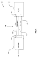
- FIG. 1 is a block diagram of a serial link data system
- FIG. 2 is a block diagram illustration of a system structured and arranged in accordance with an embodiment of the present invention
- FIG. 3 is a tabular illustration of exemplary protocols used to transfer multi-channel audio data within the system of FIG. 2;
- FIG. 4 is an illustration of an exemplary timing diagram of stereo data segments structured in accordance with an embodiment of the present invention.
- FIG. 5 is a exemplary timing diagram of a multi-channel data segment structured in accordance with the present invention.
- FIG. 6. is a flowchart of an exemplary method of practicing the present invention.
- FIG. 7 is a block diagram illustration of an exemplary computer system on which the present invention can be practiced.
- FIG. 1 is a block diagram illustration of a system 100 used to facilitate an audio connection between modules within an IC.
- the system 100 includes a transmitter 102 and a receiver 104 respectively configured for transmitting and receiving audio-related data signals.
- the transmitter 102 and the receiver 104 provide interconnections for modules within PCB and/or IC-based components such as digital signal processors, digital filters, and digital input/output interfaces, also noted above.
- the transmitter 102 and the receiver 104 are connected by a serial data bus 106.
- the serial data bus 106 includes a clock line 108 for transferring timing information between the transmitter 102 and the receiver 104.
- the transmitter 102 generates a bit clock signal along the clock line 108.
- the transmitter 102 also includes a word select signal 110 and a serial data stream 112. In more complex systems, there may be several transmitters and several receivers.
- the system 100 includes the 3-line data bus 106 for transferring input audio information 115 between the transmitter 102 and the receiver 104.
- the I 2 S protocol suite is used for formatting the clock bit data transferred along the clock line 108, the word select data 110, and the serial data stream 112.
- the transmitter 102 of FIG. 1 includes a standard audio encoder 113 configured for converting received data 115 into a format for transfer across the data bus 106.
- the receiver 104 includes a conventional audio decoder 114 configured to decode the encoded audio data received via the data path 106.
- the encoder 113 can be used, for example, to convert received audio PCM data into an I 2 S format or the popular Sony/Philips digital interface (SPDIF) format.
- I 2 S systems are suitable for a variety of applications.
- I 2 S-based systems can include many different hardware configurations and protocol variations. Accommodating these variations and differences can lead to an introduction of errors during chip design. These design errors can include left/right swaps, overflow, and left/right phase mismatches.
- the I 2 S approach also defines a clock locked to the data rate as part of the interface, thus complicating silicon clock networks. Additionally, as also noted above, an I 2 S conversion is required of all incoming audio data in order to facilitate transfer of data along the data path 106 between the transmitter 102 and the receiver 104.
- FIG. 2 is an illustration of an exemplary system 200 structured and arranged in accordance with an embodiment of the present invention.
- the system 200 includes a 2-line serial multi-channel audio interconnect (MAI) data bus.
- the 2-line MAI bus of FIG. 2 can be used to transfer digitized data samples of any audio data rate, or a compressed audio bit stream of any rate, providing it is clocked at a sufficiently high frequency. Therefore, the clock rate of the multi-channel audio interconnect bus of the system 200 does not need to be locked to a specific data rate.
- the MAI bus of the system 200 eliminates the need to convert to the I 2 S format, and thus reduces the number of clock domains. Consequently, the number of data lines can be reduced from 3 to 2.
- the communication system 200 includes a transmitting module 202 structured to receive input audio data 203.
- a receiver 204 is also included.
- the receiver 204 includes a MAI decoder 205 structured to decode MAI-encoded input audio data.
- a MAI data bus 206 provides a connection between the transmitting module 202 and the receiver 204.
- the MAI data bus 206 includes a synchronization line 207 and a data line 208.
- the synchronization line 207 is structured for transmitting a synchronization (sync) pulse between the transmitting module 202 and the receiver module 204. This sync pulse acts as a timing trigger to control the clocking of data transmitted along the data line 208.
- sync synchronization
- the transmitting module 202 includes an MAI encoder 211 configured to convert data, requiring transmission, into an MAI protocol format.
- the transmitting module 202 may also optionally includes a standard audio decoder 212.
- the audio decoder 212 can be, for example, a demodulator, or some other device to convert the received input audio data 203 into a more conventional processing format.
- the more conventional format can include, for example, baseband pulse code modulated (PCM) form.
- the transmitter 202 can also optionally include an MAI decoder 213 to translate any incoming MAI data, transferred along another MAI bus into the transmitting module 202.
- another signal processing module 214 that can be used, for example, to convert data into a predetermined digital format.
- the output of the MAI decoder 213 can be provided to the MAI encoder 211 and/or to an exemplary digital video interface device (DVI) 215.
- DVI digital video interface device
- the system 200 optionally includes a broadcasting television system committee (BTSC) intermediate frequency (I/F) demodulation device 216.
- the BTSC device 216 can include an MAI decoder 218.
- the BTSC device 216 receives an RF signal 220 as an input, demodulates the received RF input, and encodes corresponding demodulated data into an MAI format for transmission across an MAI bus 222 as an input by the transmitter 202.
- the system 200 also optionally includes additional destination devices such as an additional receiver 224, configured to receive audio information based upon the MAI protocols.
- FIG. 3 provides a tabular illustration 300 of exemplary MAI protocols associated with transmitting audio data via the MAI data bus 206.
- the protocols are structured in the form of a 32 bit format data word.
- the table 300 includes a description section, illustrating modes of the data MAI protocols and a mnemonic section corresponding to the illustrated modes. Also included is a bit section identifying exemplary bits used to configure the data word to corresponding modes.
- the exemplary data word protocols illustrated in the table 300 include a MAI bus version identification number segment 302, an audio stream ID 304, and an audio sampling rate segment 306.
- the table 300 also includes an audio format segment 308 to indicate whether the transmitted data is mono, stereo, surround sound, or other audio format.
- a sample width segment 310 is included along with a reserved section 312 for future capabilities.
- the version mnemonic 302 can track a specific kit version for mapping with data.
- the audio stream ID 304 can be used to represent a multilingual transmission, musical versions, ratings of musical versions, or can be used to indicate data streams to be received by different destination sources. For example, one audio stream ID can be used to indicate a data transmission to be received by the receiver 204 and another transmission to be received by the receiver 224.
- the audio format portion 308 can be used to define a data format. The audio format portion 308 can also be used to convert the audio data into a form that resembles a conventional audio data transmission.
- FIG. 4 is an illustration of an exemplary format 400 for transmitting audio information segments 402 using the MAI bus 206 or 222 of FIG. 2.
- the audio information segments 402 can be transmitted along the data line 208 or the data path 222 of FIG. 2.
- An exemplary synchronization pulse stream 404 is transmitted across the sync line 207 to provide timing for the audio information segments 402.
- a clock signal 406 is generated by a system clock, produces the clock input 210.
- the clock input 210 is provided to 202, 204, 216 and 224.
- a suitable system clock rate is 108 MHz.
- the MAI bus 206 and the MAI bus 222 of FIG. 2 can support up to 35 audio channels of 96 KHz sampling rate with 32 bit resolution. This rate is also sufficient to accommodate standard 5.1 surround sound audio channels and accommodate future expansion.
- the audio information segments 402 include a format portion 408 and a data portion 410.
- the format portion 408 is structured and arrayed in accordance with the table 300 of FIG. 3.
- the data portion 410 includes exemplary left and right channels representative of a stereo audio data transmission. In traditional communications parlance, the data portion 410 is referred to as a group of samples (GOS), including a left sample and a right sample.
- GOS group of samples
- the format portion 408 and the GOS 410 are indicative of one information audio segment, or a single data burst 411.
- Each synch pulse within the synch pulse train 404 defines the start of each information segment.
- the format portion 408 and the data portion 410 are transmitted contiguously in substantial synchronism with one of the sync pulses 404.
- the audio sampling rate field of the format portion 408 can be set for example to 32, 44.1, or 48 KHz, or any other rate indicated within the audio sampling rate mnemonic 306 of FIG. 3.
- the data burst 411 is transmitted as soon as the left/right sample pair are available.
- the delay between when the sample is available in the transmitter and when the sample is played in the receiver, will be minimized.
- the MAI encoder 211 and the MAI decoder 205 are software-programmable and can change formats and location timing of the synch pulses 404 in real-time, in accordance with the audio format word 308.
- the format 400 of FIG. 4 is one example of a source (transmitter) to destination (receiver) formatting of audio data in accordance with the MAI protocols shown in FIG. 3.
- a multi-channel format 500 includes audio information segments 502 and a synchronization pulse train 504.
- the information segments 502 include a format portion 508 and a GOS 510 representative of surround sound audio data.
- FIG. 4 and FIG. 5 illustrate stereo and surround sound audio data transmissions respectively, the present invention can accommodate any existing audio format and includes flexibility to accommodate expansion.
- the audio data 203 is received as an input to the transmitting module 202 for transmission across the MAI bus 206 to the receiver 204 for playback.
- the transmitting and receiving modules 202 and 204 respectively can be positioned within a PCB or within an IC.
- the received audio data 203 is optionally decoded within the audio decoder 212 and is provided as a baseband data signal input to the MAI encoder 211.
- the system clock input 210 acts as a timing mechanism for modules within the system 200.
- the MAI encoder 211 converts the baseband data signal into audio information segments, such as the segment 402, illustrated in FIG. 4.
- Each of the segments 402 typically includes one format portion 408 and GOS 410.
- the format portion 408 is set within the audio encoder 211. More specifically, the format word 408 is configured in accordance with characteristics of the received audio data 203. These characteristics are assessed within the MAI encoder 211.
- Each of the format modes 302-310 are configured and set in accordance with predetermined communications modes. The communications modes can be set apriorily or dynamically in accordance with the received audio data 203.
- the resulting audio information segments 402 are then transmitted across the data line 208 as soon as the first group of samples 410 have been encoded by the encoder 211. Transmission of each data burst 411 occurs in synchronism with one of the sync pulses 404, generated along the sync line 207.
- the most significant bit (MSB) of the format portion 408 is aligned with a leading edge of its corresponding synch pulse in order to commence transmission of the data burst 411.
- the audio information segments 411 are then transmitted along the MAI bus 206 and received by the MAI decoder 205 within the receiver 204.
- a different receiver 224 can be configured to also receive the audio information segments 402 transmitted along the MAI bus 206.
- the audio stream ID 302 can be encoded to forward one portion of the audio information segments 402 to the receiver 204 and another portion to the receiver 224.
- the present invention provides a 2-line serial MAI bus 206 for transmission of audio data.
- Two lines provide a more efficient transmission system than conventional 3-line systems and is less complex than 1-line systems.
- the 2-line system of the present invention also provides for a reduced IC pin count and avoids the protocol and software complexities of single line serial data systems.
- audio data is received as an input RF data signal 220 within the BTSC I/F demodulator 216.
- the RF signal 220 is encoded with the MAI protocols in the encoder 218 and configured for transmission along the MAI bus 222 to the transmitting module 202.
- the optional MAI decoder 213 is structured to convert the input MAI encoded data, received via the MAI bus 222, into a secondary data format such as baseband PCM.
- the data can then be provided to an optional processor 214 such as a DAC, and at the same time provided to the DVI 215 for forwarding to yet another destination component (not shown).
- the data received from the MAI bus 222, and within the MAI decoder 213, is forwarded directly to the MAI encoder 211 for transmission across the MAI bus 206 to one or both of the receiving modules 204 and 224.
- the transmitting module 202 is shown to include the MAI encoder 211, the audio decoder 212, the MAI decoder 213, and an optional signal processing component 214, many different combinations of MAI compatible components can be included within the transmitter 202. Similarly, many different embodiments of the receivers 204 and 224 can be used within the context of the present invention.
- FIG. 6 is an exemplary method 600 of practicing the present invention.
- audio information segments are transmitted or received on a first signal line, as indicated in block 602.
- a data portion includes audio data corresponding to one or more of the format modes, noted above.
- a number of synch markers is correspondingly transferred or received on a second signal line, as indicated in block 604. Each marker is representative of a timing of one of the audio information segments.
- the technique of the present invention provides an efficient technique for transferring audio data between modules within a PCB and/or an IC.
- the present technique provides a protocol for transferring this data using a 2-line data bus that can be used to transfer digitized samples at any audio rate, or a compressed audio bit stream of any rate, providing it is clocked at an appropriate high frequency.
- the clock rate of the MAI bus of the present invention need not be locked to the data rate.
- a sync pulse indicates the start of the transfer of a data burst of a group of samples. Following a 32-bit format word that defines specific formats regarding the data to be transferred, the data samples are transferred and the bus remains idle until the next group of samples is ready to be transmitted.
- the present invention can be implemented in hardware, software, firmware, and/or combinations thereof. Consequently, the invention may be implemented in the environment of a computer system or other processing system. An example of such a computer system 700 is shown in FIG. 7.
- the computer system 700 includes one or more processors, such as a processor 704.
- the processor 704 can be a special purpose or a general purpose digital signal processor.
- the processor 704 is connected to a communication infrastructure 706 (for example, a bus or network).
- a communication infrastructure 706 for example, a bus or network.
- the computer system 700 also includes a main memory 708, preferably random access memory (RAM), and may also include a secondary memory 710.
- the secondary memory 710 may include, for example, a hard disk drive 712 and/or a removable storage drive 714, representing a floppy disk drive, a magnetic tape drive, an optical disk drive, etc.
- the removable storage drive 714 reads from and/or writes to a removable storage unit 718 in a well known manner.
- the removable storage unit 718 represents a floppy disk, magnetic tape, optical disk, etc. which is read by and written to by removable storage drive 714.
- the removable storage unit 718 includes a computer usable storage medium having stored therein computer software and/or data.
- the secondary memory 710 may include other similar means for allowing computer programs or other instructions to be loaded into the computer system 700.
- Such means may include, for example, a removable storage unit 722 and an interface 720.
- Examples of such means may include a program cartridge and cartridge interface (such as that found in video game devices), a removable memory chip (such as an EPROM, or PROM) and associated socket, and the other removable storage units 722 and the interfaces 720 which allow software and data to be transferred from the removable storage unit 722 to the computer system 700.
- the computer system 700 may also include a communications interface 724.
- the communications interface 724 allows software and data to be transferred between the computer system 700 and external devices. Examples of the communications interface 724 may include a modem, a network interface (such as an Ethernet card), a communications port, a PCMCIA slot and card, etc.
- Software and data transferred via the communications interface 724 are in the form of signals 728 which may be electronic, electromagnetic, optical or other signals capable of being received by the communications interface 724. These signals 728 are provided to the communications interface 724 via a communications path 726.
- the communications path 726 carries the signals 728 and may be implemented using wire or cable, fiber optics, a phone line, a cellular phone link, an RF link and other communications channels.
- computer readable medium and “computer usable medium” are used to generally refer to media such as the removable storage drive 714, a hard disk installed in the hard disk drive 712, and the signals 728.
- These computer program products are means for providing software to the computer system 700.
- Computer programs are stored in the main memory 708 and/or the secondary memory 710. Computer programs may also be received via the communications interface 724. Such computer programs, when executed, enable the computer system 700 to implement the present invention as discussed herein.
- the computer programs when executed, enable the processor 704 to implement the processes of the present invention. Accordingly, such computer programs represent controllers of the computer system 700.
- the processes/methods performed by signal processing blocks of encoders and/or decoders can be performed by computer control logic.
- the software may be stored in a computer program product and loaded into the computer system 700 using the removable storage drive 714, the hard drive 712 or the communications interface 724.
Landscapes
- Engineering & Computer Science (AREA)
- Multimedia (AREA)
- Signal Processing (AREA)
- Information Transfer Systems (AREA)
- Communication Control (AREA)
- Time-Division Multiplex Systems (AREA)
Abstract
Description
According to an aspect of the invention, a method for communicating audio comprises:
- transmitting audio information segments on a first signal line, each segment including (i) a format portion representative of audio format modes and (ii) a data portion having audio data corresponding to one or more of the format modes; and
- transmitting a number of synchronization markers on a second signal line, each marker being representative of a timing of one of the audio information segments.
Advantageously, the information segments are unmodulated.
Advantageously, the information segments are representative of one or more audio channels.
Advantageously, the format portion comprises a 32 bit data word.
Advantageously, the format modes include at least one of a version number, an audio stream ID, an audio sampling rate, an audio format, and a sample width.
Advantageously, the audio stream ID includes an indication of an intended recipient of one or more of the transmitted audio segments.
Advantageously, the format modes are dynamic.
Advantageously, the format modes are configured to vary from one information segment to another information segment.
Advantageously, the synchronization marker include sync pulses.
Advantageously, each sync pulse represents a start of one information segment transmission.
According to an aspect of the invention, a method for communicating audio comprises:
- receiving audio information segments on a first signal line, each segment including (i) a format portion representative of audio format modes and (ii) a data portion having audio data corresponding to one or more of the format modes; and
- receiving a number of synchronization markers on a second signal line, each marker being representative of a timing of one of the audio information segments.
Advantageously, the information segments are representative of one or more audio channels.
Advantageously, the format portion comprises a 32 bit data word.
Advantageously, each sync pulse represents a start of one information segment reception.
According to an aspect of the invention, a communication system is provided including a data path configured for transferring audio data between a transmitting module and one or more receiving modules, the transmitting and receiving modules being formed on a printed circuit board, the system comprising:
- an encoder positioned within the transmitting module and configured to convert audio data requiring transmission into two-line audio information segments,
- a data line having a first end coupled to a first data port of the encoder and configured to transmit the audio information segments, the audio information segments including (i) a format portion including at least an audio format indication and (ii) a data portion including data corresponding to the audio format indication;
- a synchronization line having a first end coupled to a second data port configured to transmit a number of sync pulses each being indicative of a start of one of the audio information segments; and
- a decoder positioned within the receiving module and having first and second ports respectively coupled to first and second data ports of the decoder, the decoder being configured to convert the received two-line audio information segments into audio data.
Advantageously, the data line is configured for transmitting multi-channel audio data.
Advantageously, the format portion includes a 32 bits format word.
Claims (10)
- A method for communicating audio, comprising:transmitting audio information segments on a first signal line, each segment including (i) a format portion representative of audio format modes and (ii) a data portion having audio data corresponding to one or more of the format modes.
- The method of claim 1, further comprising transmitting a number of synchronization markers on a second signal line, each marker being representative of a timing of one of the audio information segments.
- The method of claim 1 or 2, wherein the audio comprises a serial bit stream.
- The method of any of the preceding claims, wherein the information segments are unmodulated.
- A method for communicating audio, comprising:receiving audio information segments on a first signal line, each segment including (i) a format portion representative of audio format modes and (ii) a data portion having audio data corresponding to one or more of the format modes; andreceiving a number of synchronization markers on a second signal line, each marker being representative of a timing of one of the audio information segments.
- The method of claim 5, wherein the information segments are unmodulated.
- The method of claim 5 or 6, wherein the information segments are representative of one or more audio channels.
- A communication system including a data path configured for transferring audio data between a transmitting module and one or more receiving modules, the transmitting and receiving modules being formed on a printed circuit board, the system comprising:an encoder positioned within the transmitting module and configured to convert audio data requiring transmission into two-line audio information segments;a data line having a first end coupled to a first data port of the encoder and configured to transmit the audio information segments, the audio information segments including (i) a format portion including at least an audio format indication and (ii) a data portion including data corresponding to the audio format indication;a synchronization line having a first end coupled to a second data port configured to transmit a number of sync pulses each being indicative of a start of one of the audio information segments; anda decoder positioned within the receiving module and having first and second ports respectively coupled to first and second data ports of the decoder, the decoder being configured to convert the received two-line audio information segments into audio data.
- The system of claim 8, wherein the transmitting and receiving modules are formed on an integrated circuit.
- The system of claim 8 or 9, wherein the data line is configured for transmitting multi-channel audio data.
Applications Claiming Priority (4)
| Application Number | Priority Date | Filing Date | Title |
|---|---|---|---|
| US49512703P | 2003-08-15 | 2003-08-15 | |
| US495127P | 2003-08-15 | ||
| US646833 | 2003-08-25 | ||
| US10/646,833 US7764671B2 (en) | 2003-08-15 | 2003-08-25 | Method and system for a multi-channel audio interconnect bus |
Publications (2)
| Publication Number | Publication Date |
|---|---|
| EP1524770A2 true EP1524770A2 (en) | 2005-04-20 |
| EP1524770A3 EP1524770A3 (en) | 2005-04-27 |
Family
ID=34138974
Family Applications (1)
| Application Number | Title | Priority Date | Filing Date |
|---|---|---|---|
| EP04017519A Withdrawn EP1524770A3 (en) | 2003-08-15 | 2004-07-23 | Method and apparatus for transmitting digital audio signals |
Country Status (2)
| Country | Link |
|---|---|
| US (1) | US7764671B2 (en) |
| EP (1) | EP1524770A3 (en) |
Families Citing this family (5)
| Publication number | Priority date | Publication date | Assignee | Title |
|---|---|---|---|---|
| US7489362B2 (en) | 2003-03-04 | 2009-02-10 | Broadcom Corporation | Television functionality on a chip |
| CN101479969B (en) * | 2006-06-26 | 2012-07-04 | Nxp股份有限公司 | Method and device for data encapsulation |
| KR101319549B1 (en) * | 2007-07-16 | 2013-10-21 | 삼성전자주식회사 | Transmission and receive method of audio data and electronic apparatus using that |
| EP2672393A1 (en) | 2012-06-04 | 2013-12-11 | Dialog Semiconductor B.V. | Circuit and methods to use an audio interface to program a device within an audio stream |
| TWI695313B (en) * | 2019-02-15 | 2020-06-01 | 矽統科技股份有限公司 | Device and method for detecting audio interface |
Family Cites Families (5)
| Publication number | Priority date | Publication date | Assignee | Title |
|---|---|---|---|---|
| US5889820A (en) | 1996-10-08 | 1999-03-30 | Analog Devices, Inc. | SPDIF-AES/EBU digital audio data recovery |
| JP3206458B2 (en) * | 1996-10-18 | 2001-09-10 | 日本電気株式会社 | DMA transfer method |
| US6205223B1 (en) | 1998-03-13 | 2001-03-20 | Cirrus Logic, Inc. | Input data format autodetection systems and methods |
| US7088398B1 (en) * | 2001-12-24 | 2006-08-08 | Silicon Image, Inc. | Method and apparatus for regenerating a clock for auxiliary data transmitted over a serial link with video data |
| US6957284B2 (en) * | 2002-01-16 | 2005-10-18 | Microsoft Corporation | System and method for pendant bud for serially chaining multiple portable pendant peripherals |
-
2003
- 2003-08-25 US US10/646,833 patent/US7764671B2/en not_active Expired - Fee Related
-
2004
- 2004-07-23 EP EP04017519A patent/EP1524770A3/en not_active Withdrawn
Also Published As
| Publication number | Publication date |
|---|---|
| EP1524770A3 (en) | 2005-04-27 |
| US7764671B2 (en) | 2010-07-27 |
| US20050036508A1 (en) | 2005-02-17 |
Similar Documents
| Publication | Publication Date | Title |
|---|---|---|
| US20010008535A1 (en) | Interconnection of audio/video devices | |
| US8154657B2 (en) | Method and related device for determining timing sequence of video and audio data for high density multimedia interface | |
| EP0535434A2 (en) | A circuit and method for communicating digital audio information | |
| MX2010004149A (en) | Preamble for a digital television system. | |
| US7764671B2 (en) | Method and system for a multi-channel audio interconnect bus | |
| US6804655B2 (en) | Systems and methods for transmitting bursty-asnychronous data over a synchronous link | |
| EP1643487B1 (en) | Audio decoding apparatus | |
| US8489212B2 (en) | Audio data transmission and reception methods and electronic apparatus using the same | |
| KR101077028B1 (en) | Method and Apparatus for Transmitting Audio Data | |
| US6826179B1 (en) | Packet channel implementation | |
| EP1605687B1 (en) | System for receiving packet streams | |
| US6697381B1 (en) | Packet channel architecture | |
| US20050108778A1 (en) | Method and apparatus for simultaneous display of multiple audio/video programs transmitted over a digital link | |
| US7286602B2 (en) | Method of data transmission for N-channel digital data in an M-channel block format | |
| CN207732909U (en) | A kind of multi-functional asynchronous transport system of AES3/EBU digital audio | |
| JP3733064B2 (en) | Bus control device | |
| KR20010017264A (en) | Data communication method | |
| US20250301030A1 (en) | Method and apparatus for encoding and multiplexing a stream in a serial channel | |
| JP2005252470A (en) | Transmission apparatus and transmission method | |
| CN117939222B (en) | DVB frequency point locking and data processing method and system | |
| KR100853153B1 (en) | Digital broadcast receiver | |
| US20040090392A1 (en) | Image transmission system | |
| JP4884034B2 (en) | Audio output device | |
| WO2004100163A3 (en) | Method and apparatus for enabling sub-channel recording and playback | |
| CN121713165A (en) | Multi-channel audio input mixer |
Legal Events
| Date | Code | Title | Description |
|---|---|---|---|
| PUAI | Public reference made under article 153(3) epc to a published international application that has entered the european phase |
Free format text: ORIGINAL CODE: 0009012 |
|
| PUAL | Search report despatched |
Free format text: ORIGINAL CODE: 0009013 |
|
| AK | Designated contracting states |
Kind code of ref document: A2 Designated state(s): AT BE BG CH CY CZ DE DK EE ES FI FR GB GR HU IE IT LI LU MC NL PL PT RO SE SI SK TR |
|
| AX | Request for extension of the european patent |
Extension state: AL HR LT LV MK |
|
| AK | Designated contracting states |
Kind code of ref document: A3 Designated state(s): AT BE BG CH CY CZ DE DK EE ES FI FR GB GR HU IE IT LI LU MC NL PL PT RO SE SI SK TR |
|
| AX | Request for extension of the european patent |
Extension state: AL HR LT LV MK |
|
| 17P | Request for examination filed |
Effective date: 20051027 |
|
| AKX | Designation fees paid |
Designated state(s): DE FR GB |
|
| RAP1 | Party data changed (applicant data changed or rights of an application transferred) |
Owner name: BROADCOM CORPORATION |
|
| 17Q | First examination report despatched |
Effective date: 20110216 |
|
| STAA | Information on the status of an ep patent application or granted ep patent |
Free format text: STATUS: THE APPLICATION IS DEEMED TO BE WITHDRAWN |
|
| 18D | Application deemed to be withdrawn |
Effective date: 20150202 |