EP1524601A2 - A method of storing data on a secondary storage device - Google Patents
A method of storing data on a secondary storage device Download PDFInfo
- Publication number
- EP1524601A2 EP1524601A2 EP04104932A EP04104932A EP1524601A2 EP 1524601 A2 EP1524601 A2 EP 1524601A2 EP 04104932 A EP04104932 A EP 04104932A EP 04104932 A EP04104932 A EP 04104932A EP 1524601 A2 EP1524601 A2 EP 1524601A2
- Authority
- EP
- European Patent Office
- Prior art keywords
- data
- data source
- storage device
- unique identifier
- secondary storage
- Prior art date
- Legal status (The legal status is an assumption and is not a legal conclusion. Google has not performed a legal analysis and makes no representation as to the accuracy of the status listed.)
- Ceased
Links
Images

Classifications
-
- G—PHYSICS
- G06—COMPUTING OR CALCULATING; COUNTING
- G06F—ELECTRIC DIGITAL DATA PROCESSING
- G06F11/00—Error detection; Error correction; Monitoring
- G06F11/07—Responding to the occurrence of a fault, e.g. fault tolerance
- G06F11/14—Error detection or correction of the data by redundancy in operation
- G06F11/1402—Saving, restoring, recovering or retrying
- G06F11/1446—Point-in-time backing up or restoration of persistent data
- G06F11/1458—Management of the backup or restore process
- G06F11/1464—Management of the backup or restore process for networked environments
-
- G—PHYSICS
- G06—COMPUTING OR CALCULATING; COUNTING
- G06F—ELECTRIC DIGITAL DATA PROCESSING
- G06F11/00—Error detection; Error correction; Monitoring
- G06F11/07—Responding to the occurrence of a fault, e.g. fault tolerance
- G06F11/14—Error detection or correction of the data by redundancy in operation
- G06F11/1402—Saving, restoring, recovering or retrying
- G06F11/1446—Point-in-time backing up or restoration of persistent data
- G06F11/1456—Hardware arrangements for backup
-
- G—PHYSICS
- G06—COMPUTING OR CALCULATING; COUNTING
- G06F—ELECTRIC DIGITAL DATA PROCESSING
- G06F3/00—Input arrangements for transferring data to be processed into a form capable of being handled by the computer; Output arrangements for transferring data from processing unit to output unit, e.g. interface arrangements
- G06F3/06—Digital input from, or digital output to, record carriers, e.g. RAID, emulated record carriers or networked record carriers
- G06F3/0601—Interfaces specially adapted for storage systems
- G06F3/0602—Interfaces specially adapted for storage systems specifically adapted to achieve a particular effect
- G06F3/0604—Improving or facilitating administration, e.g. storage management
- G06F3/0607—Improving or facilitating administration, e.g. storage management by facilitating the process of upgrading existing storage systems, e.g. for improving compatibility between host and storage device
-
- G—PHYSICS
- G06—COMPUTING OR CALCULATING; COUNTING
- G06F—ELECTRIC DIGITAL DATA PROCESSING
- G06F3/00—Input arrangements for transferring data to be processed into a form capable of being handled by the computer; Output arrangements for transferring data from processing unit to output unit, e.g. interface arrangements
- G06F3/06—Digital input from, or digital output to, record carriers, e.g. RAID, emulated record carriers or networked record carriers
- G06F3/0601—Interfaces specially adapted for storage systems
- G06F3/0628—Interfaces specially adapted for storage systems making use of a particular technique
- G06F3/0662—Virtualisation aspects
- G06F3/0664—Virtualisation aspects at device level, e.g. emulation of a storage device or system
-
- G—PHYSICS
- G06—COMPUTING OR CALCULATING; COUNTING
- G06F—ELECTRIC DIGITAL DATA PROCESSING
- G06F3/00—Input arrangements for transferring data to be processed into a form capable of being handled by the computer; Output arrangements for transferring data from processing unit to output unit, e.g. interface arrangements
- G06F3/06—Digital input from, or digital output to, record carriers, e.g. RAID, emulated record carriers or networked record carriers
- G06F3/0601—Interfaces specially adapted for storage systems
- G06F3/0668—Interfaces specially adapted for storage systems adopting a particular infrastructure
- G06F3/0671—In-line storage system
- G06F3/0683—Plurality of storage devices
- G06F3/0686—Libraries, e.g. tape libraries, jukebox
-
- G—PHYSICS
- G06—COMPUTING OR CALCULATING; COUNTING
- G06F—ELECTRIC DIGITAL DATA PROCESSING
- G06F11/00—Error detection; Error correction; Monitoring
- G06F11/07—Responding to the occurrence of a fault, e.g. fault tolerance
- G06F11/14—Error detection or correction of the data by redundancy in operation
- G06F11/1402—Saving, restoring, recovering or retrying
- G06F11/1446—Point-in-time backing up or restoration of persistent data
- G06F11/1458—Management of the backup or restore process
- G06F11/1469—Backup restoration techniques
Definitions
- This invention generally relates to computer systems and more particularly to backup systems and methods.
- Computer data protection systems usually involve the backup of system and data files onto some sort of secondary storage device utilizing removable storage media, such as floppy disk drives, other hard disk drives, tape drives, etc. More sophisticated users may utilize automatic data protection devices and procedures that backup the entire system on a regular basis, allowing for a full system recovery if needed.
- tape backup systems are used to protect data files and other information from computer system failures such as hard disk crashes or computer virus attacks.
- a tape backup system stores this data on removable off-line media (i.e., the tape); this data can then be retrieved in the event of data loss.
- Conventional backup systems typically provide the end user with a choice of making a "full” backup or an "incremental” or “modified” backup.
- Full backups make complete copies of all the data on the computer to a set of one or more backup tapes.
- Incremental backups are generally much smaller than full backups since they simply save the data that has been changed since either the last full backup or the most recent incremental backup. Examples of such prior art backup systems are described in U.S. Pat. No. 5,276,860, U.S. Pat. No. 5,758,067, U.S. Pat. No. 6,212,512, U.S. Pat. No. 6,330,570 and WO 01/31431 A2.
- FIG. 1 shows a block diagram of a prior art computer system which enables interleaved backups.
- Host computers 10, 12, 14 are coupled to backup server computer 16 by means of network 18.
- network 18 is a local area network (LAN).
- Backup server computer 16 is coupled to tape drive 20 by means of storage area network (SAN) 22.
- LAN local area network
- SAN storage area network
- the backup server computer 16 communicates with the host computers 10, 12 and 14 over network 18 in order to pull the backup data from the host computers 10, 12 and 14.
- the backup server computer interleaves the respective data streams received from host computers 10, 12 and 14 before sending the single interleaved data stream to tape drive 20 via storage area network 22.
- backup server computer 16 serves as a central hub for the entire backup process. This implies that the backup server computer must be capable of handling the high data rates of the backup data from the host computers at both its inputs and its output. Further this requires sophisticated backup software and makes restoring the data dependent on that particular interleaving capability.
- Another disadvantage is that the streaming of the backup data from the host computers to the backup server computer over the network 18 may saturate the transmission capacity of the network 18. This is a severe problem as network 18 is often a production network that is required for ongoing operational activities and is not optimised for storage activities.
- LTO technology is an "open format” technology, which means that users can have multiple sources of media and compatible tape drives.
- the ULTRIUM format is the "high capacity" implementation of LTO technology (hftp.//www.Ito-technology.com).
- LTO compliant cartridge has a non-volatile cartridge memory (LTO-CM) which is an intelligent memory chip embedded in the cartridge. It uses a radio frequency interface that eliminates the need for a physical power or signal connection between cartridge and tape drive.
- LTO-CM non-volatile cartridge memory
- the LTO-CM is used for storing information which in other tape formats may be stored in the header at the beginning of the tape.
- the present invention provides for a method of storing data of at least first and second data sources on a single secondary storage device, such as a tape drive.
- a number of secondary storage devices are emulated by the single secondary storage device.
- the emulated secondary storage devices receive data from the data sources which is tagged with respective unique identifiers of the data sources.
- the tagged data is stored on a storage medium, such as a tape.
- a storage medium such as a tape.
- the present invention is particularly useful for storing of backup data streams originating from a plurality of host computers on a single sequential storage device, such as a tape drive.
- the invention can also be used for storing of such data streams on random access storage devices.
- a plurality of host computers is coupled to the single secondary storage device via a storage area network (SAN).
- a SAN connects a group of hosts to their shared storage devices, such as disks, disk arrays and tape drives, through an interconnection fabric which typically comprises hubs, switches and links.
- FibreChannel (www.fibrechannel.com) is used as the communication protocol in a SAN. Communication links are established through the SAN between each one of the host computers and respective dedicated emulated secondary storage devices provided by the single secondary storage device. Backup data is received by the emulated secondary storage devices from the host computers. The backup data is interleaved in order to provide a single data stream which is stored on a removable storage medium by the single secondary storage device.
- each data source has a predefined unique identifier.
- WWNs of the host computer systems are communicated to the emulated secondary storage devices when the communication links are established by means of the FibreChannel protocol.
- the WWNs or a portion of the WWNs can be used for tagging of the backup data before interleaving.
- a mapping may be established between the WWNs and simple indexes, and these indexes then used to tag the data. The mapping table would then be stored either on the tape medium or in the cartridge memory.
- a look up table is generated which comprises the unique identifiers and host computer details, such as host computer names.
- the look up table is stored on non-volatile memory of the storage medium; for example, the non-volatile memory is a memory chip being attached to a tape cartridge and which is accessed via a RF interface or by a set of electrical contacts from the tape storage device.
- the look up table is stored in the LTO-CM.
- the look up table is stored on the tape itself.
- the host computer In the case of a restore being needed to the host computer that originally performed the backup, the host computer would identify itself to the tape drive through its WWN. The tape drive would then only route data back to that host that was originally flagged with that host's WWN. Data that is identified as being from other hosts would be passed over.
- One way of using the look up table is for replacing the host computer such as for disaster recovery or migration where the original identifier (the WWN) is no longer available. Initially it is necessary to recreate a suitable system on which to restore the data, including all hardware, the basic operating system, and a restore application. Then, the look up table is visualised on the user interface of the replacement host computer system for a user's selection of the original host which is to be replaced. The unique identifier of the replacement host computer system is communicated to the single secondary storage device for mapping of the unique identifier of the original host computer system to the unique identifier of the replacement host computer system. This way data which is tagged with the unique identifier of the original host computer system is restored to the replacement host computer system.
- present invention is not restricted to tape storage devices having a single tape drive.
- present invention can also be applied to tape libraries which comprise multiple tape drives.
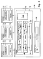
- FIG. 2 shows tape storage device 100 having processor 102 and tape drive 104.
- Processor 102 executes emulation program component 106 for emulation of multiple tape drives and tagging program component 108 for tagging of backup data received by the emulated tape drives with the respective identifiers.
- the tagged data is interleaved by interleaver 110.
- Control program 112 controls operation of the various components of tape storage device 100, in particular tape drive 104.
- a number of data sources, A, B, C, are coupled to tape storage device 100.
- Each one of the data sources A, B, C, has a processor 114 which runs backup application 116.
- Each one of the data sources A, B, C, has storage 118 for storage of a unique identifier (ID).
- ID unique identifier
- Emulation program component 106 provides a virtual tape drive for each one of the data sources, A, B, C, which are coupled to tape storage device 100.
- emulation program component 106 provides emulation 119 of virtual tape drive A which is coupled to data source A.
- emulation program component 106 provides emulation 120 of virtual tape drive B which is coupled to data source B and emulation 122 of tape drive C which is coupled to data source C, etc.
- Tagging program component 108 has modules 124, 126, 128, for tagging of data.
- Module 124 is assigned to emulation 119 and tags data which are received by emulation 119 with a unique identifier of data source A.
- module 126 is assigned to emulation 120 and tags data received by emulation 120 from data source B with unique identifier B.
- Module 128 is assigned to emulation 122 and tags data which are received by emulation 122 from data source C with unique identifier C, etc.
- tape cartridge 130 is inserted into tape drive 104.
- Data sources A, B, C, ... are coupled to tape storage device 100 and backup applications 116 on data sources A, B, C, ... are started.
- Backup application 116 of data source A communicates with emulation 119 of tape storage device 100 and sends backup data from data source A to emulation 119.
- Emulation 119 forwards the data received from data source A to module 124 where the data is tagged with the unique identifier A.
- backup application 116 of data source B sends data to emulation 120 which forwards the data to module 126.
- Module 126 tags the data with the unique identifier B of data source B. The same applies analogously to the further emulations 122, ... of emulation program component 106 and modules 128, ... of tagging program component 108.
- the tagged data of data sources A, B, C, ... is provided from tagging program component 108 to interleaver 110 where the tagged data is interleaved to provide a data stream from interleaver 110 to tape drive 104; the data stream is written onto tape contained in tape cartridge 130.
- Overall operation of tape storage device 100 is controlled by control program 112.
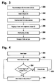
- FIG. 3 shows a corresponding method.
- the tape storage device receives the unique identifiers from various data sources which are coupled to the tape storage device.
- the unique identifiers of the various data sources are stored by tape storage device in step 202.
- step 204 the tape storage device emulates a tape drive for each one of the data sources; by means of the emulated tape drives the tape storage device receives respective data from the various data sources (step 204).
- step 206 the data is tagged with the respective unique identifier of the data source from which the data originates.
- step 208 the tagged data is interleaved to provide a data stream which is stored on tape in step 210. This way a single tape storage device can be used by a plurality of data sources in order to make maximum usage of the media access bandwidth provided by the tape drive.
- Figure 4 shows a flow chart for performing a restore operation.
- step 300 a tape on which backup data has been stored in accordance with the method of figure 3 is inserted into the tape drive.
- data is read from the tape.
- step 304 it is determined whether the data is tagged with the unique identifier of the data source for which the restore operation is performed. Without restriction of generality it is assumed that the data source for which the restore operation is performed is the data source A. If the data is tagged with the unique identifier of the data source A the data is sent to the data source A in step 308 from which the control returns to step 302. If the contrary is the case the data is ignored in step 306 and the control goes back to step 302.
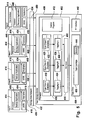
- Figure 5 shows a block diagram of a number of host computer systems, i.e. host A, B, C, ... which are coupled through storage area network 432 to tape storage device 400. Elements of the embodiment of figure 5 which correspond to elements of the embodiment of figure 2 are designated with like reference numerals having added 300.
- each one of the hosts has a unique world wide name (WWN) which is stored in memory 418.
- WWN world wide name
- each one of the hosts A, B, C, ... can have an assigned host name which is stored in memories 434.
- tape storage device 400 has RF interface 442 to non-volatile memory 444 arranged on tape cartridge 430.
- non-volatile memory 444 is an LTO-CM cartridge memory.
- RF interface 442 data can be written to non-volatile memory 444 and read from non-volatile memory 444 by tape storage device 400 under control of control program 412.
- communication links 436, 438, 440 are established by means of the FibreChannel protocol between host A and emulation 419, host B and emulation 420, host C and emulation 422, etc.
- the communication links 436, 438, 440 are formed the WWNs of host A, B, C, ... are communicated to tape storage device 400 via the FibreChannel protocol.
- the respective host names can be transmitted to the tape storage device 400 when the communication links 436, 438, 440, ... are formed.
- One way of implementing the functionality is additional software to run on each host computer. This can be a separate application that was to run before of after the backup application, or it can be included in a development of the backup application.
- the tape drive control program 412 supports a capability to accept a specific command that is used to update its look-up table. Control program 412 assigns a unique identifier to each WWN and corresponding host name. The resulting look up table is stored in memory 444 through RF interface 442. Alternatively the look up table can also be stored directly on the tape of tape cartridge 430, or on the tape and non-volatile memory for redundancy.
- One of the hosts A, B, C, ... may need replacement for various reasons, such as migration to a more powerful host computer system or due to loss of a host computer because of fire, theft, etc.
- host A needs to be replaced by host A'.
- Host A' has recovery application 446 which is executed by processor 414. Recovery application 446 generates user interface 448.
- host A' In order to initiate the replacement of A by host A' , host A' is coupled to storage area network 432 and communication link 450 is established between host A' and tape storage device 400, i.e. emulation 419, by means of the FibreChannel protocol.
- Tape cartridge 430 containing the tape with the backup data is inserted in tape drive 404 and the look up table which is stored in non-volatile memory 444 is read by means of RF interface 442.
- the look up table is transmitted from tape storage device 400 to host A' via communication link 450.
- Recovery application 446 visualises the look up table on user interface 448.
- a user can select one of the host names of the look up table in order to specify which one of the hosts needs replacement. In the example considered here the user selects the host name of host A.
- This user selection as well as the WWN and host name of host A' are transmitted over communication link 450 to tape storage device 400.
- Control program 412 maps the unique identifier A which had been assigned to host A to the WWN and host name of the replacement host A'.
- Next data packets which are tagged with the unique identifier A of the host A are read from the tape contained in tape cartridge 430 by means of tape drive 404. These data packets are sent by control program 412 to host A' over communication link 450. This way the backup data of host A is provided to replacement host A'.
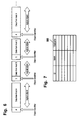
- Figure 6 illustrates the tagging of backup data of logical objects received by the tape storage device from the host computers.
- a logical object is comprised of a sequential stream of data transferred from a host computer in a single write-to-tape operation.
- a logical object which is received by the tape storage device from host A is tagged with the unique identifier A which is assigned to that host computer A.
- the unique identifier A serves to unequivocably identify that logical object as originating from host A.
- a logical object received from host B is tagged with unique identifier B, etc.
- a logical object which is received from one of the hosts in a single transaction is tagged with a single unique identifier.
- Figure 7 shows look up table 500 which is stored on non-volatile memory of the tape cartridge (cf. memory 444 of figure 4).
- Each row of look up table 500 has three entries, i.e. a unique identifier (ID), a WWN and a host name.
- ID unique identifier
- WWN unique identifier
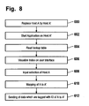
- FIG 8 shows a corresponding flow chart.
- the host A is physically replaced by host A', such as for the purpose of migration or disaster recovery.
- a recovery application program is started on host A'.
- the look up table (cf. look up table 500 of figure 5) is read from the non-volatile memory of the tape cartridge. The look up table is visualised on the user interface of host A' in step 606 by the recovery application program.
- step 608 a user inputs his or her selection of the host which needs to be replaced, which is host A in the example considered here.
- step 610 the WWN and host name of the replacement host A' are assigned to the original unique identifier of host A. This way a logical mapping of host A to host A' is performed for the purposes of the recovery procedure.
- step 612 the backup data which is tagged with the unique identifier of host A is sent to host A'.
Landscapes
- Engineering & Computer Science (AREA)
- Theoretical Computer Science (AREA)
- Physics & Mathematics (AREA)
- General Engineering & Computer Science (AREA)
- General Physics & Mathematics (AREA)
- Human Computer Interaction (AREA)
- Quality & Reliability (AREA)
- Library & Information Science (AREA)
- Information Retrieval, Db Structures And Fs Structures Therefor (AREA)
- Techniques For Improving Reliability Of Storages (AREA)
- Signal Processing For Digital Recording And Reproducing (AREA)
Abstract
Description
- Figure 1
- is a block diagram of a prior art backup system which is based on a central backup server computer
- Figure 2
- is a block diagram of a backup system for multiple data sources,
- Figure 3
- is a flow chart of a backup method,
- Figure 4
- is a flow chart of a restore method,
- Figure 5
- is a block diagram of a SAN-based backup system,
- Figure 6
- illustrates the tagging of logical objects with identifiers,
- Figure 7
- illustrates a look up table,
- Figure 8
- is a flow chart of a host computer replacement method, such as for the purposes of disaster recovery or migration.
- 100
- Tape storage device
- 102
- Processor
- 104
- Tape drive
- 106
- Emulation program component
- 108
- Tagging program component
- 110
- Interleaver
- 112
- Control program
- 114
- Processor
- 116
- Backup application
- 118
- Memory
- 119
- Emulation
- 120
- Emulation
- 122
- Emulation
- 124
- Module
- 126
- Module
- 128
- Module
- 130
- Tape cartridge
- 400
- Tape storage device
- 402
- Processor
- 404
- Tape drive
- 406
- Emulation program component
- 408
- Tagging program component
- 410
- Interleaver
- 412
- Control program
- 414
- Processor
- 416
- Backup application
- 419
- emulation
- 420
- Emulation
- 422
- Emulation
- 424
- Module
- 426
- Module
- 428
- Module
- 430
- Tape cartridge
- 432
- Storage area network
- 434
- Memory
- 436
- Communication link
- 438
- Communication link
- 440
- Communication link
- 442
- RF interface
- 444
- Non-volatile memory
- 446
- Recovery application
- 448
- User interface
- 450
- Communication link
- 500
- Look up table
Claims (28)
- A method of storing data from at least first and second data sources using a single secondary storage device (100; 400), the method comprising:emulating at least first and second secondary storage devices using the single secondary storage device,receiving first data from the first data source using the emulated first secondary storage device and tagging the received first data with a unique identifier of the first data source,receiving second data from the second data source using the emulated second secondary storage device and tagging the received second data with a unique identifier of the second data source,storing the tagged first and second data on a storage medium (130; 430) using the single secondary storage device.
- The method of claim 1, wherein the first and second data sources are first and second host computers.
- The method of claim 1 or 2, the at least first and second data sources being coupled to the single secondary storage device via a storage area network (432).
- The method of claim 1, 2 or 3, further comprising establishing a first communication link between the first data source and the emulated first secondary storage device and establishing a second communication link between the second data source and the emulated second secondary storage device, wherein the first and second communication links are established by means of a fibre channel protocol.
- The method of any one of the preceding claims 1 to 4, further comprising receiving the unique identifier of the first data source from the first data source and receiving the unique identifier of the second data source from the second data source.
- The method of any one of the preceding claims 1 to 5, wherein the unique identifier of the first data source is the world wide name (WWN) of the first data source and the unique identifier of the second data source is the world wide name of the second data source.
- The method of any one of the preceding claims 1 to 6, wherein the first and second data are received as first and second data packets, and further comprising tagging each one of the data packets with the respective unique identifier and interleaving of the tagged data packets for sequential storage on the storage medium by the single secondary storage device.
- The method of any one of the preceding claims 1 to 7, further comprising storing in non-volatile memory (130; 430, 444) an index (500) comprising the unique identifiers.
- The method of claim 8, the non-volatile memory being the storage medium.
- The method of claim 8, the non-volatile memory being a cartridge memory of the storage medium.
- The method of any one of the preceding claims 1 to 10, the single secondary storage device being a tape drive residing in a tape library comprising a plurality of tape drives.
- The method of claim 8, the index comprising a mapping table (500) of the unique identifiers and respective names of the data sources.
- A computer program product for storing data of at least first and second data sources using a single secondary storage device (100; 400), the computer program product comprising program means for:emulating at least first and second secondary storage devices by using the single secondary storage device,receiving first data from the first data source using the emulated first secondary storage device and tagging the received first data with a unique identifier of the first data source,receiving second data from the second data source using the emulated second secondary storage device and tagging the received second data with a unique identifier of the second data source,storing the tagged first and second data on a storage medium (130; 430) using the single secondary storage device.
- The computer program product of claim 13, the program means being adapted to store a list of the unique identifiers and respective names of the data sources on non-volatile memory (130; 430, 444).
- A method of restoring data to a data source of a plurality of data sources, the method comprising:identifying data packets tagged with a unique identifier of the data source in a sequence of data packets stored on a removable storage medium, each one of the data packets being tagged with a unique identifier of a respective one of the plurality of data sources,restoring the identified data packets to the data source.
- The method of claim 15, further comprising replacing the data source by another data source and mapping the unique identifier of the data source to the unique identifier of the replacement data source for restoring the identified data packets to the replacement data source.
- The method of claim 16, whereby the data source is replaced for the purpose of disaster recovery or migration.
- A computer program product for restoring data to a data source of a plurality of data sources, the computer program product comprising program means for:identifying data packets tagged with a unique identifier of the data source in a sequence of data packets stored on a removable storage medium (130; 430), each one of the data packets tagged with a unique identifier of a respective one of the plurality of data sources,restoring the identified data packets to the data source.
- The computer program product of claim 18, the program means being adapted to map the unique identifier of the data source to a unique identifier of a replacement data source in order to restore the identified data packets to the replacement data source.
- A method of replacing a data source of a plurality of data sources by a replacement data source, the method comprising:reading a look up table (500) from non-volatile memory of a removable storage medium, the look up table comprising unique identifiers of the data sources and respective data source names,visualising the look up table on a user interface (448),enabling selection of one of the data sources by a user via the user interface,mapping the unique identifier of the replacement data source to the unique identifier of the selected data source,identifying data packets tagged with the unique identifier of the selected data source in a sequence of data packets stored on the removable storage medium,restoring the identified data packets to the replacement data source.
- A computer program product for replacing a data source of a plurality of data sources by a replacement data source, the computer program product comprising program means for:reading a look up table (500) from non-volatile memory (130; 430, 444) of a removable storage medium, the look up table comprising unique identifiers of data sources and respective data source names,visualising the look up table on a user interface (448) for a user's selection of one of the data sources to be replaced,mapping the unique identifier of the selected data source to the unique identifier of the replacement data source,receiving data packets tagged with the unique identifier of the selected data source for restoring to the replacement data source.
- A secondary storage device for storing data of at least first and second data sources on a removable storage medium, the secondary storage device comprising:means (119, 120, 122; 419, 420, 422) for emulating at least first and second secondary storage devices,means (124, 126, 128; 424, 426, 428) for tagging data received from one of the at least first and second data sources with a unique identifier of the one of at least first and second data sources,means (104; 404) for storing of the tagged data on a removable storage medium.
- The secondary storage device of claim 22, further comprising means (112; 412) for generating a look up table (500) comprising unique identifiers of the at least first and second data sources and respective names of the at least first and second data sources, and means for storing of the look up table on non-volatile memory of the removable storage medium.
- The secondary storage device of claim 22 or 23, further comprising means (110; 410) for interleaving the tagged data.
- The secondary storage device of claim 22, 23 or 24 being a tape backup storage apparatus, wherein the means for emulating provide a plurality of emulated tape drives for coupling of a plurality of data sources, the means for tagging data comprising a program component for tagging data packets received from one of the data sources of the plurality of data sources with a unique identifier of the one of the data sources and for interleaving the tagged data of different ones of the data sources, and the means for storing of the tagged data comprising a tape drive for sequential storage of the interleaved, tagged data on a backup tape.
- The secondary storage device of claim 25, further comprising a program component for generating a look up table comprising unique identifiers of the data sources and data source names and for storing of the look up table on non-volatile memory of the backup tape.
- The secondary storage device of any one of the preceding claims 22 to 26, the secondary storage device being a tape drive that is adapted to be coupled to at least first and second host computers providing the first and second data sources, respectively.
- A tape library comprising at least one tape drive in accordance with any one of the preceding claims 22 to 27.
Applications Claiming Priority (2)
| Application Number | Priority Date | Filing Date | Title |
|---|---|---|---|
| GB3234879 | 2003-10-08 | ||
| GB0323487A GB2407175A (en) | 2003-10-08 | 2003-10-08 | A method of storing data on a secondary storage device |
Publications (2)
| Publication Number | Publication Date |
|---|---|
| EP1524601A2 true EP1524601A2 (en) | 2005-04-20 |
| EP1524601A3 EP1524601A3 (en) | 2011-06-01 |
Family
ID=29433446
Family Applications (1)
| Application Number | Title | Priority Date | Filing Date |
|---|---|---|---|
| EP04104932A Ceased EP1524601A3 (en) | 2003-10-08 | 2004-10-08 | A method of storing data on a secondary storage device |
Country Status (3)
| Country | Link |
|---|---|
| US (2) | US7979647B2 (en) |
| EP (1) | EP1524601A3 (en) |
| GB (1) | GB2407175A (en) |
Families Citing this family (37)
| Publication number | Priority date | Publication date | Assignee | Title |
|---|---|---|---|---|
| GB2407659A (en) * | 2003-10-31 | 2005-05-04 | Hewlett Packard Development Co | Disaster recovery using multiple boot images held on a sequential storage device |
| GB2419026B (en) * | 2004-10-08 | 2009-05-06 | Hewlett Packard Development Co | Tape drive apparatus |
| EP1657642A1 (en) * | 2004-11-11 | 2006-05-17 | Siemens AG | Procedure for persistent storage of DHCP subscriber data |
| US7814260B2 (en) * | 2005-03-09 | 2010-10-12 | Bakbone Software, Inc. | Tape image on non-tape storage device |
| US20060288057A1 (en) * | 2005-06-15 | 2006-12-21 | Ian Collins | Portable data backup appliance |
| US7747577B2 (en) * | 2005-08-17 | 2010-06-29 | International Business Machines Corporation | Management of redundant objects in storage systems |
| US20070162271A1 (en) * | 2005-10-12 | 2007-07-12 | Storage Appliance Corporation | Systems and methods for selecting and printing data files from a backup system |
| US8069271B2 (en) * | 2005-10-12 | 2011-11-29 | Storage Appliance Corporation | Systems and methods for converting a media player into a backup device |
| US20070091746A1 (en) * | 2005-10-12 | 2007-04-26 | Storage Appliance Corporation | Optical disc for simplified data backup |
| US7813913B2 (en) * | 2005-10-12 | 2010-10-12 | Storage Appliance Corporation | Emulation component for data backup applications |
| US8195444B2 (en) * | 2005-10-12 | 2012-06-05 | Storage Appliance Corporation | Systems and methods for automated diagnosis and repair of storage devices |
| US20080028008A1 (en) * | 2006-07-31 | 2008-01-31 | Storage Appliance Corporation | Optical disc initiated data backup |
| US7899662B2 (en) * | 2005-10-12 | 2011-03-01 | Storage Appliance Corporation | Data backup system including a data protection component |
| US7702830B2 (en) * | 2005-10-12 | 2010-04-20 | Storage Appliance Corporation | Methods for selectively copying data files to networked storage and devices for initiating the same |
| US7818160B2 (en) * | 2005-10-12 | 2010-10-19 | Storage Appliance Corporation | Data backup devices and methods for backing up data |
| US7844445B2 (en) | 2005-10-12 | 2010-11-30 | Storage Appliance Corporation | Automatic connection to an online service provider from a backup system |
| US7822595B2 (en) * | 2005-10-12 | 2010-10-26 | Storage Appliance Corporation | Systems and methods for selectively copying embedded data files |
| US7962499B2 (en) | 2006-08-18 | 2011-06-14 | Falconstor, Inc. | System and method for identifying and mitigating redundancies in stored data |
| US20080082453A1 (en) * | 2006-10-02 | 2008-04-03 | Storage Appliance Corporation | Methods for bundling credits with electronic devices and systems for implementing the same |
| US20080126446A1 (en) * | 2006-11-27 | 2008-05-29 | Storage Appliance Corporation | Systems and methods for backing up user settings |
| US20080172487A1 (en) * | 2007-01-03 | 2008-07-17 | Storage Appliance Corporation | Systems and methods for providing targeted marketing |
| US20080226082A1 (en) * | 2007-03-12 | 2008-09-18 | Storage Appliance Corporation | Systems and methods for secure data backup |
| US20090030955A1 (en) * | 2007-06-11 | 2009-01-29 | Storage Appliance Corporation | Automated data backup with graceful shutdown for vista-based system |
| US20090031298A1 (en) * | 2007-06-11 | 2009-01-29 | Jeffrey Brunet | System and method for automated installation and/or launch of software |
| US8413137B2 (en) * | 2010-02-04 | 2013-04-02 | Storage Appliance Corporation | Automated network backup peripheral device and method |
| US9286253B2 (en) * | 2011-01-21 | 2016-03-15 | Hewlett Packard Enterprise Development Lp | System and method for presenting devices through an SAS initiator-connected device |
| US9710356B2 (en) * | 2011-09-19 | 2017-07-18 | International Business Machines Corporation | Assertions in a business rule management system |
| US9274888B2 (en) * | 2013-11-15 | 2016-03-01 | Qualcomm Incorporated | Method and apparatus for multiple-bit DRAM error recovery |
| US9348837B2 (en) * | 2013-12-05 | 2016-05-24 | International Business Machines Corporation | Index writing in a linear tape file system |
| WO2015167432A1 (en) | 2014-04-28 | 2015-11-05 | Hewlett-Packard Development Company, L.P. | Storage management |
| US10241703B2 (en) | 2016-06-21 | 2019-03-26 | International Business Machines Corporation | Multivolume group management |
| US11461054B2 (en) * | 2019-04-23 | 2022-10-04 | EMC IP Holding Company LLC | Concurrent tape access |
| US11106605B2 (en) * | 2019-04-23 | 2021-08-31 | EMC IP Holding Company LLC | Enhanced tape drive communication |
| US11061568B2 (en) * | 2019-06-19 | 2021-07-13 | International Business Machines Corporation | Variable operation tape performance |
| US11262952B2 (en) * | 2019-07-19 | 2022-03-01 | EMC IP Holding Company LLC | Concurrent tape modification |
| US20230236865A1 (en) * | 2022-01-25 | 2023-07-27 | Dell Products, L.P. | Locating Virtual Tape File Systems on a Virtual Tape Emulator |
| US12461662B2 (en) | 2024-04-03 | 2025-11-04 | SanDisk Technologies, Inc. | Data storage device and method for enhancing fault tolerance |
Citations (3)
| Publication number | Priority date | Publication date | Assignee | Title |
|---|---|---|---|---|
| WO2001084265A2 (en) | 2000-04-28 | 2001-11-08 | Neartek Inc. | Backup and restore system for data derived from a plurality of host equipment in heterogeneous environment |
| WO2002012993A1 (en) | 2000-08-04 | 2002-02-14 | Neartek, Inc. | Virtual storage system |
| US6487644B1 (en) | 1996-11-22 | 2002-11-26 | Veritas Operating Corporation | System and method for multiplexed data back-up to a storage tape and restore operations using client identification tags |
Family Cites Families (16)
| Publication number | Priority date | Publication date | Assignee | Title |
|---|---|---|---|---|
| US5276860A (en) | 1989-12-19 | 1994-01-04 | Epoch Systems, Inc. | Digital data processor with improved backup storage |
| US5212772A (en) * | 1991-02-11 | 1993-05-18 | Gigatrend Incorporated | System for storing data in backup tape device |
| US5758067A (en) | 1995-04-21 | 1998-05-26 | Hewlett-Packard Co. | Automated tape backup system and method |
| US5778395A (en) * | 1995-10-23 | 1998-07-07 | Stac, Inc. | System for backing up files from disk volumes on multiple nodes of a computer network |
| US5950218A (en) * | 1996-11-04 | 1999-09-07 | Storage Technology Corporation | Method and system for storage and retrieval of data on a tape medium |
| US6219799B1 (en) * | 1997-07-01 | 2001-04-17 | Unisys Corporation | Technique to support pseudo-names |
| EP0945800B1 (en) | 1998-03-02 | 2003-07-16 | Hewlett-Packard Company, A Delaware Corporation | Data backup system |
| US6279011B1 (en) * | 1998-06-19 | 2001-08-21 | Network Appliance, Inc. | Backup and restore for heterogeneous file server environment |
| CA2244626A1 (en) * | 1998-07-31 | 2000-01-31 | Kom Inc. | A hardware and software system |
| US6212512B1 (en) | 1999-01-06 | 2001-04-03 | Hewlett-Packard Company | Integration of a database into file management software for protecting, tracking and retrieving data |
| US6631442B1 (en) * | 1999-06-29 | 2003-10-07 | Emc Corp | Methods and apparatus for interfacing to a data storage system |
| US6842841B1 (en) * | 1999-09-21 | 2005-01-11 | Storage Technology Corporation | Method and system for dynamically selecting tape drives to connect with host computers |
| US6816957B1 (en) | 1999-10-26 | 2004-11-09 | Storage Technology Corporation | Management of virtual tape volumes using data page atomic units |
| US20030046313A1 (en) * | 2001-08-31 | 2003-03-06 | Arkivio, Inc. | Techniques for restoring data based on contents and attributes of the data |
| US20030120676A1 (en) * | 2001-12-21 | 2003-06-26 | Sanrise Group, Inc. | Methods and apparatus for pass-through data block movement with virtual storage appliances |
| US7082497B2 (en) * | 2001-12-28 | 2006-07-25 | Hewlett-Packard Development Company, L.P. | System and method for managing a moveable media library with library partitions |
-
2003
- 2003-10-08 GB GB0323487A patent/GB2407175A/en not_active Withdrawn
-
2004
- 2004-09-27 US US10/949,191 patent/US7979647B2/en not_active Expired - Fee Related
- 2004-10-08 EP EP04104932A patent/EP1524601A3/en not_active Ceased
-
2011
- 2011-05-04 US US13/100,435 patent/US8140779B2/en not_active Expired - Lifetime
Patent Citations (3)
| Publication number | Priority date | Publication date | Assignee | Title |
|---|---|---|---|---|
| US6487644B1 (en) | 1996-11-22 | 2002-11-26 | Veritas Operating Corporation | System and method for multiplexed data back-up to a storage tape and restore operations using client identification tags |
| WO2001084265A2 (en) | 2000-04-28 | 2001-11-08 | Neartek Inc. | Backup and restore system for data derived from a plurality of host equipment in heterogeneous environment |
| WO2002012993A1 (en) | 2000-08-04 | 2002-02-14 | Neartek, Inc. | Virtual storage system |
Also Published As
| Publication number | Publication date |
|---|---|
| GB2407175A (en) | 2005-04-20 |
| US20110208999A1 (en) | 2011-08-25 |
| GB0323487D0 (en) | 2003-11-12 |
| EP1524601A3 (en) | 2011-06-01 |
| US20080133827A1 (en) | 2008-06-05 |
| US8140779B2 (en) | 2012-03-20 |
| US7979647B2 (en) | 2011-07-12 |
Similar Documents
| Publication | Publication Date | Title |
|---|---|---|
| US8140779B2 (en) | Method of storing data on a secondary storage device | |
| US11775180B2 (en) | Tape library emulation with automatic configuration and data retention | |
| US8055870B2 (en) | Tape storage emulation for open systems environments | |
| JP3895677B2 (en) | System for managing movable media libraries using library partitioning | |
| US7958305B1 (en) | System and method for managing storage networks and providing virtualization of resources in such a network | |
| US6598174B1 (en) | Method and apparatus for storage unit replacement in non-redundant array | |
| US7107395B1 (en) | Apparatus and methods for operating a computer storage system | |
| US8656100B1 (en) | System and method for managing provisioning of storage resources in a network with virtualization of resources in such a network | |
| US6845431B2 (en) | System and method for intermediating communication with a moveable media library utilizing a plurality of partitions | |
| US6311240B1 (en) | Hardware assisted formatted data transfer system having a source storage controller and a formatting storage controller receiving on-media structure definition and a data definition | |
| US6842833B1 (en) | Computer system and method for transferring data between multiple peer-level storage units | |
| JP2002366310A (en) | Method and system for backing up data in a storage system | |
| JP2003316607A (en) | Storage system operation management method | |
| WO2001053945A2 (en) | Method and apparatus for transferring data between a primary storage system and a secondary storage system using a bridge volume | |
| US7620775B1 (en) | System and method for managing storage networks and providing virtualization of resources in such a network using one or more ASICs | |
| US7620774B1 (en) | System and method for managing storage networks and providing virtualization of resources in such a network using one or more control path controllers with an embedded ASIC on each controller | |
| EP1324536B1 (en) | A method for managing data transfers in a computer network | |
| US7124324B1 (en) | Method of testing fiber channel ports in a storage server at full bandwidth without connection to external devices | |
| US7260612B2 (en) | Switching system duplicating file operation command according to quantity of file servers and sending writing and reading commands according to a switching order | |
| US9218313B2 (en) | Shared-bandwidth multiple target remote copy |
Legal Events
| Date | Code | Title | Description |
|---|---|---|---|
| PUAI | Public reference made under article 153(3) epc to a published international application that has entered the european phase |
Free format text: ORIGINAL CODE: 0009012 |
|
| AK | Designated contracting states |
Kind code of ref document: A2 Designated state(s): AT BE BG CH CY CZ DE DK EE ES FI FR GB GR HU IE IT LI LU MC NL PL PT RO SE SI SK TR |
|
| AX | Request for extension of the european patent |
Extension state: AL HR LT LV MK |
|
| PUAL | Search report despatched |
Free format text: ORIGINAL CODE: 0009013 |
|
| AK | Designated contracting states |
Kind code of ref document: A3 Designated state(s): AT BE BG CH CY CZ DE DK EE ES FI FR GB GR HU IE IT LI LU MC NL PL PT RO SE SI SK TR |
|
| AX | Request for extension of the european patent |
Extension state: AL HR LT LV MK |
|
| 17P | Request for examination filed |
Effective date: 20111123 |
|
| AKX | Designation fees paid |
Designated state(s): DE FR GB |
|
| 17Q | First examination report despatched |
Effective date: 20120608 |
|
| STAA | Information on the status of an ep patent application or granted ep patent |
Free format text: STATUS: THE APPLICATION HAS BEEN REFUSED |
|
| 18R | Application refused |
Effective date: 20130603 |