EP1524590A2 - Tracking motion using an interference pattern - Google Patents
Tracking motion using an interference pattern Download PDFInfo
- Publication number
- EP1524590A2 EP1524590A2 EP04011418A EP04011418A EP1524590A2 EP 1524590 A2 EP1524590 A2 EP 1524590A2 EP 04011418 A EP04011418 A EP 04011418A EP 04011418 A EP04011418 A EP 04011418A EP 1524590 A2 EP1524590 A2 EP 1524590A2
- Authority
- EP
- European Patent Office
- Prior art keywords
- sensor
- sensors
- signal
- interference pattern
- speckle
- Prior art date
- Legal status (The legal status is an assumption and is not a legal conclusion. Google has not performed a legal analysis and makes no representation as to the accuracy of the status listed.)
- Withdrawn
Links
Images

Classifications
-
- G—PHYSICS
- G06—COMPUTING OR CALCULATING; COUNTING
- G06F—ELECTRIC DIGITAL DATA PROCESSING
- G06F3/00—Input arrangements for transferring data to be processed into a form capable of being handled by the computer; Output arrangements for transferring data from processing unit to output unit, e.g. interface arrangements
- G06F3/01—Input arrangements or combined input and output arrangements for interaction between user and computer
- G06F3/03—Arrangements for converting the position or the displacement of a member into a coded form
- G06F3/0304—Detection arrangements using opto-electronic means
- G06F3/0317—Detection arrangements using opto-electronic means in co-operation with a patterned surface, e.g. absolute position or relative movement detection for an optical mouse or pen positioned with respect to a coded surface
-
- G—PHYSICS
- G06—COMPUTING OR CALCULATING; COUNTING
- G06F—ELECTRIC DIGITAL DATA PROCESSING
- G06F3/00—Input arrangements for transferring data to be processed into a form capable of being handled by the computer; Output arrangements for transferring data from processing unit to output unit, e.g. interface arrangements
- G06F3/01—Input arrangements or combined input and output arrangements for interaction between user and computer
- G06F3/03—Arrangements for converting the position or the displacement of a member into a coded form
- G06F3/033—Pointing devices displaced or positioned by the user, e.g. mice, trackballs, pens or joysticks; Accessories therefor
- G06F3/0354—Pointing devices displaced or positioned by the user, e.g. mice, trackballs, pens or joysticks; Accessories therefor with detection of two-dimensional [2D] relative movements between the device, or an operating part thereof, and a plane or surface, e.g. 2D mice, trackballs, pens or pucks
- G06F3/03545—Pens or stylus
Definitions
- This disclosure relates to motion tracking and more specifically to such motion tracking for use in a computer navigational device.
- the traditional computer navigational device uses an interior rolling ball to track its motion across a surface.
- the optical mouse was developed in response to problems with the common roller-ball mouse.
- An optical mouse does not have moving parts, but instead contains a sensor array arranged to take successive images of the surface supporting the mouse. Each image of the surface is compared to the proceeding image, and from this comparison a system can determine how far the mouse has moved. This system may not always operate effectively if the imaged surface is smooth.
- Such devices use the constructive and destructive interference of the electromagnetic waves to form patterns of high and low intensity areas called speckle patterns.
- speckle patterns The contrast and size of these patterns may take various forms dependent upon, among other things, the coherency or lack of coherency of the electromagnetic waves as well as the arrangement of the device.
- Embodiments track motion across a surface by reflecting coherent light off of that surface to create an interference pattern.
- the interference patter is detected with at least one sensor to produce at least one signal corresponding to the detection of at least one dimension of an aspect of the interference pattern.
- the detected dimension is measured and from the measurement there is determined a distance traveled by the sensor.
- the dimension is measured by correlation with an assumed value.
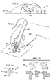
- FIGURES 1 and 2 are schematics illustrating embodiments of navigational devices
- FIGURE 3a is a schematic illustrating one embodiment of a sensor arrangement
- FIGURE 3b is a schematic illustrating one embodiment of an interference pattern
- FIGURES 4a and 4b are schematics illustrating an interaction of a sensor arrangement for horizontal motion detection
- FIGURE 4c is a graph relating to sensor signals
- FIGURES 5a and 5b are schematics illustrating interactions of sensor arrangements for vertical motion detection
- FIGURE 5c is a graph relating to sensor signals
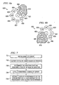
- FIGURES 6a and 6b are schematics illustrating interactions of sensors arranged for polar coordinates.
- FIGURE 7 is a flow diagram of one embodiment in accordance with the invention.
- FIGURES 1 and 2 show embodiments of computer navigational devices using electromagnetic waves (light) for sensing relative movement.
- the embodiments shown use a laser to emit coherent light that can be reflected off of a surface.
- the resulting interference pattern consists of a pattern of light and dark aspects, called speckles, when observed or detected.
- speckles a pattern of light and dark aspects
- the dimensions of an individual speckle are primarily a function of certain device parameters, such as the wavelength of the incident light, the diameter of the laser beam, and the distance of the observer or the photo sensor from the reflecting surface. If the light parameters are held constant, an embodiment can anticipate that values for the dimensions of the formed speckles will to within a fixed Gaussian distribution where approximately 95% of the speckles are within 60% in size.
- an embodiment can anticipate that 95% of the resulting speckles will have dimensions within some known range of values. If a large number of speckles are used, this consistency may be sufficient to enable a system to count the speckles as they pass and determine the distance of motion across a surface.
- each speckle width (or other appropriate pattern aspect dimension, such as speckle length, the distance between speckles, the distance between the front edge of two speckles, or the distance between the trailing edges of two speckles) is, in fact, the statistical average for that dimension as determined by the arrangement of the system.
- ⁇ is wavelength
- R is distance from the reflection point
- d is diameter of the beam.
- computer mouse 100 holds laser 110 and sensor cluster 120.
- Laser 110 emits coherent light 111 which reflects off of surface 130 producing interference phenomena, speckles 121.
- Laser 110 and sensor cluster 120 are held fixed with respect to each other, but the interference pattern 121 will move, with respect to sensor cluster 120, as computer mouse 100 moves across surface 130.
- stylus 200 houses laser 210 and sensor cluster 220.
- laser 210 projects coherent light 211 at an angle close to the radial axis of stylus 200 that reflects coherent light 211 off of a surface 230 to produce an interference pattern of speckles 221 which is then perceived by sensor cluster 220.
- the orientation of stylus 200 is important to the calculations.
- groove 251 is provided for the proper placement of the fingers of hand 250 as it grips stylus 200.
- FIGURE 3a is a diagram illustrating several aspects of one embodiment in relation to an interference phenomena, such as speckles produced by laser light reflecting off a surface.
- sensor cluster 300 is arranged in accordance with one embodiment.
- Five sensors 301-305 are arranged in a cross pattern with sensor 301 at its center.
- Sensors 302, 303, 304 and 305 are then arranged on the points of a compass north, east, south, and west, respectively.
- FIGURE 3b shows interference pattern 310 composed of speckles, such as speckle 311.
- the speckles are designed to be approximately twice the size of sensors 301-305.
- a typical optical mouse may have 250 or more fairly large sensors in order to accommodate the variation in surfaces a user may use. Sensors as small as 5 microns are currently available, which would result in an entire sensor array less than 50 microns across. If a sensor is used that is smaller than the speckles created, counting the speckles may be easier. By adjusting the distance of the sensors from the scattering surface, the speckle size can be varied, and a distance of 1 to 2 centimeters may be sufficient to produce speckles of 5 to 10 microns in size.
- Embodiments may use sensors with a diameter of 5 microns, and an average speckle size of approximately 10 microns. At this size, an embodiment could encounter approximately 2500 speckles per inch of movement.
- direction can be determined by the successive triggering of linked sensors. If only a single sensor is triggered by the presence of a speckle, no information can be gleaned regarding direction. If, however, a speckle triggers first one and then a second of a linked group of sensors, direction can be determined from the arrangement of the linked sensors.
- the north 302, center 301, and south 304 sensors of FIGURE 3a are arranged in a vertical line. Embodiments may use a method of linking sensors in order to provide for the determination of direction. In FIGURE 3 a, if a speckle triggers north sensor 302, then center sensor 301, and then south sensor 304, a determination can be made that the speckle is traveling from the north to the south.
- the comparison of linked sensors can lead to a positive, negative, or zero direction state.
- Embodiments arranged such as in FIGURE 3 a can link the sensors in the vertical line and link the sensors in the horizontal line, and compare the signals of these linked sensors to determine direction states of+1, -1, or 0 along the vertical and the horizontal Cartesian axis.
- a sensor of the sensor cluster detects the presence of a speckle creating a change (such as a rise) in the signal of the sensor.
- an embodiment queries the signals of the linked sensors.
- the system compares the signals of the linked sensors and determines a direction state of the sensor cluster from this comparison.
- an embodiment may note that the signal of the original sensor indicates that the speckle is no longer being detected (a fall in the signal).
- an embodiment would determine the distance traveled by correlating the rise and fall of the signal to the length of an average speckle, or other suitable dimension of the interference pattern.
- the embodiments are not limited to determining a distance from a measurement of the width of a speckle. Rather, any dimension of an interference pattern can be used if a suitable statistical average can be obtained.
- FIGURES 4a, 4b, and 4c relate to example sensor cluster 400 as it interacts with speckle 411.
- sensor cluster 400 has moved one-quarter of the way over speckle 411.
- FIGURE 4b depicts sensor cluster 400 having moved three-quarters of the way through speckle 411.
- FIGURE 4c is a graphical depiction of signals 401c, 403c, and 405c of sensors 401, 403, and 405 as they move through the entire range of motion depicted in FIGURES 4a and 4b.
- east sensor 403 will be the first to detect speckle 411.
- sensor 403's detection of speckle 411 is represented in signal 403c by signal rise 421.
- speckle 411 will be detected by center sensor 401.
- sensor 401's detection of speckle 411 is represented in signal 401 c by signal rise 422.
- sensor 405 detects speckle 411 which registers as rise 424 on signal 405c of FIGURE 4c.
- signal 403c experiences signal drop 425.
- speckle 411 will fall out of range of center sensor 401 resulting in signal drop 427 of 401c.
- sensor 405 will experience signal drop 428 in signal 405c.
- the point in direction 406 depicted by FIGURE 4a is seen on graph 450 at point 423.
- the point in direction 406 depicted by FIGURE 4b is seen on graph 450 at point 426.
- FIGURES 5a, 5b, and 5c relate to the interaction of sensor cluster 500 with speckle 511 as sensor cluster 500 moves 506 across speckle 511.
- FIGURE 5a depicts sensor cluster 500 as one-quarter of the way across speckle 511.
- FIGURE 5b depicts sensor cluster 500 as it is moved three-quarters of the way across speckle 511.
- FIGURE 5c graphically represents the signals 501c, 502c, and 504c generated by sensors 501, 502, and 504, as they pass completely across speckle 511. As cluster 500 moves in direction 506, southern sensor 504 will be the first to detect speckle 511, as seen by rise 521 of signal 504c.
- signals 504c and 501c have registered the presence of speckle 511 through rise 521 and rise 522.
- detector 502 will detect speckle 511 as noted by signal rise 524.
- signal 504c exhibits signal drop 525.
- the direction 506, as depicted in FIGURE 5b, is illustrated graphically at point 526 of FIGURE 5c where center sensor 501 still detects speckle 511 and northern sensor 502 also detects speckle 511.
- center sensor 501 will no longer detect speckle 511 resulting in signal drop 527 in signal 501c.
- sensor 506 will not longer detect speckle 511 resulting in drop 528 of signal 506c.
- embodiments can use a comparison of the signals of certain sensors.
- direction along the horizontal axis may be determined by comparing the signals of sensors of 401, 403, and 405.
- the system may link each sensor with at least one of the other sensors and compare the signals to determine a direction state. For example, when signal 403c of eastern sensor 403 experiences a rise, 403c is compared to what is occurring in signal 401c of center sensor 401. If center sensor signal 401c is low, an embodiment would not register a direction and conclude a direction state of zero. If, however, signal 401 c of center sensor 401 is high, an embodiment could determine that the sensor cluster was moving from east to west.
- Embodiments thus typically designed with a sensor one-half the size of the average speckle. With this ratio, and proper spacing of the sensors, a single speckle can be detected by two adjacent sensors at the same time.
- signal 401c of the center sensor 401 If a rise is seen in signal 401c of the center sensor 401, an embodiment could then compare this signal to both signal 403c of eastern sensor 403 and signal 405c of western sensor 405. If a rise is seen in signal 401c of center sensor 401, and signal 403c of eastern sensor 403 is high while the signal 405c of western center 405 is low, the system can determine a direction state of +1 in the horizontal, meaning that sensor cluster 400 was moving from west to east. If a rise is seen in signal 405c of western sensor 405, an embodiment could compare signal 405c to signal 401c for center sensor 401. If signal 401c for center sensor 401 is low, this direction state would then register a zero.
- the present invention could also determine direction along the vertical direction by comparing signals 501c, 502c, and 504c of sensors 501, 502, and 504. Again, the method would link the signal of one sensor with the signal of at least one other sensor to determine direction states. For example, if signal 501c of center sensor 501 experiences a rise, a system of an embodiment could then compare signal 501 c to signal 504c of southern sensor 504 and signal 502c of northern sensor 502. If, at this rise in signal 501 c of the center sensor 501, signal 504c of southern sensor 504 is high and signal 502c of northern sensor 502 is low, sensor cluster 500 has a vertical direction state of -1, indicating that sensor cluster 500 is moving from north to south. If when center sensor signal 501c experiences a rise, northern sensor signal 502c is high and southern sensor signal 504c is low, the vertical direction state is a +1, indicating that sensor cluster 500 is moving from south to north.
- a rise in the signals of the outside sensors 502 and 504 could trigger a comparison with signal 501c of the center sensor 501. If at the rise of signal 502c in northern sensor 502 center sensor signal 501c is low, sensor cluster 500 has a vertical direction state of zero and no direction is indicated. If, however, at the rise in signal 502c of northern sensor 502, signal 501c of center sensor is high, sensor cluster 500 would have a vertical direction state of -1, indicating that sensor cluster 500 is moving from north to south. When a rise is seen in signal 504c of southern sensor 504, the method could again compare signal 504c to signal 501c of center sensor 501 to determine direction state.
- sensor cluster 500 has a vertical state of zero. If, however, signal 501c of center sensor 501 is high at the rise of signal 504c of southern sensor 504, this direction state would register a +1 indicating that sensor cluster 500 is moving from south to north.
- a sensor cluster could be arranged to determine direction in polar coordinates, such as depicted in FIGURES 6a and 6b.
- Sensor cluster 600 is a circular arrangement of 8 sensors 601 through 608 with center sensor 609 at the approximate center of the circle described. As sensor cluster 600 interacts with speckle 610, the arrangement as depicted would be able to determine direction of motion 620 as an angle. For example, utilizing the method of linked sensors as described above, a rise in a signal of center sensor 601 could trigger a comparison of the signals of the other sensors.
- sensor 602 was high and the signals of sensors 603-609 were low, the system could determine that sensor cluster 600 was moving at a 45° angle with a direction state of -1. Similar comparisons using the other sensors would result in different direction states registering different angles of direction.
- the arrangement of FIGURES 6a and 6b could then use a method of distance determination similar to that as already described, and thus motion is tracked.
Landscapes
- Engineering & Computer Science (AREA)
- General Engineering & Computer Science (AREA)
- Theoretical Computer Science (AREA)
- Human Computer Interaction (AREA)
- Physics & Mathematics (AREA)
- General Physics & Mathematics (AREA)
- Position Input By Displaying (AREA)
- Length Measuring Devices By Optical Means (AREA)
- Optical Radar Systems And Details Thereof (AREA)
- Instruments For Measurement Of Length By Optical Means (AREA)
- Exposure Of Semiconductors, Excluding Electron Or Ion Beam Exposure (AREA)
Abstract
Description
- This disclosure relates to motion tracking and more specifically to such motion tracking for use in a computer navigational device.
- The traditional computer navigational device uses an interior rolling ball to track its motion across a surface. The optical mouse was developed in response to problems with the common roller-ball mouse. An optical mouse does not have moving parts, but instead contains a sensor array arranged to take successive images of the surface supporting the mouse. Each image of the surface is compared to the proceeding image, and from this comparison a system can determine how far the mouse has moved. This system may not always operate effectively if the imaged surface is smooth.
- Such devices use the constructive and destructive interference of the electromagnetic waves to form patterns of high and low intensity areas called speckle patterns. The contrast and size of these patterns may take various forms dependent upon, among other things, the coherency or lack of coherency of the electromagnetic waves as well as the arrangement of the device.
- Embodiments track motion across a surface by reflecting coherent light off of that surface to create an interference pattern. The interference patter is detected with at least one sensor to produce at least one signal corresponding to the detection of at least one dimension of an aspect of the interference pattern. The detected dimension is measured and from the measurement there is determined a distance traveled by the sensor. In one embodiment, the dimension is measured by correlation with an assumed value.
- FIGURES 1 and 2 are schematics illustrating embodiments of navigational devices;
- FIGURE 3a is a schematic illustrating one embodiment of a sensor arrangement;
- FIGURE 3b is a schematic illustrating one embodiment of an interference pattern;
- FIGURES 4a and 4b are schematics illustrating an interaction of a sensor arrangement for horizontal motion detection;
- FIGURE 4c is a graph relating to sensor signals;
- FIGURES 5a and 5b are schematics illustrating interactions of sensor arrangements for vertical motion detection;
- FIGURE 5c is a graph relating to sensor signals;
- FIGURES 6a and 6b are schematics illustrating interactions of sensors arranged for polar coordinates; and
- FIGURE 7 is a flow diagram of one embodiment in accordance with the invention.
- FIGURES 1 and 2 show embodiments of computer navigational devices using electromagnetic waves (light) for sensing relative movement. The embodiments shown use a laser to emit coherent light that can be reflected off of a surface. The resulting interference pattern consists of a pattern of light and dark aspects, called speckles, when observed or detected. The dimensions of an individual speckle are primarily a function of certain device parameters, such as the wavelength of the incident light, the diameter of the laser beam, and the distance of the observer or the photo sensor from the reflecting surface. If the light parameters are held constant, an embodiment can anticipate that values for the dimensions of the formed speckles will to within a fixed Gaussian distribution where approximately 95% of the speckles are within 60% in size. Therefore, by holding the parameters constant, an embodiment can anticipate that 95% of the resulting speckles will have dimensions within some known range of values. If a large number of speckles are used, this consistency may be sufficient to enable a system to count the speckles as they pass and determine the distance of motion across a surface.
- When the parameters of wavelength, laser diameter, and detector distance from surface are held constant, various embodiments may assume that each speckle width (or other appropriate pattern aspect dimension, such as speckle length, the distance between speckles, the distance between the front edge of two speckles, or the distance between the trailing edges of two speckles) is, in fact, the statistical average for that dimension as determined by the arrangement of the system. For average speckle size:
- Where λ is wavelength; R is distance from the reflection point; and d is diameter of the beam.
- As equation (1) shows, the more tightly confined the laser beam used, the larger the speckles will be in the resulting pattern. Thus, it may be possible to create speckles with a predictable Gaussian average of between 50 to 100 microns in size. By equating the average value to the actual size of each speckle, it is possible to calculate the distance traveled by counting the number of speckles that have passed.
- In the embodiment of FIGURE 1,
computer mouse 100 holdslaser 110 andsensor cluster 120. Laser 110 emitscoherent light 111 which reflects off ofsurface 130 producing interference phenomena,speckles 121. Laser 110 andsensor cluster 120 are held fixed with respect to each other, but theinterference pattern 121 will move, with respect tosensor cluster 120, ascomputer mouse 100 moves acrosssurface 130. - In the embodiment of FIGURE 2,
stylus 200houses laser 210 andsensor cluster 220. In this embodiment,laser 210 projectscoherent light 211 at an angle close to the radial axis ofstylus 200 that reflectscoherent light 211 off of asurface 230 to produce an interference pattern ofspeckles 221 which is then perceived bysensor cluster 220. In this example embodiment, the orientation ofstylus 200 is important to the calculations. Thus,groove 251 is provided for the proper placement of the fingers ofhand 250 as it gripsstylus 200. - FIGURE 3a is a diagram illustrating several aspects of one embodiment in relation to an interference phenomena, such as speckles produced by laser light reflecting off a surface. In FIGURE 3a,
sensor cluster 300 is arranged in accordance with one embodiment. Five sensors 301-305 are arranged in a cross pattern withsensor 301 at its center.Sensors - FIGURE 3b shows
interference pattern 310 composed of speckles, such asspeckle 311. In the embodiment depicted, the speckles are designed to be approximately twice the size of sensors 301-305. - A typical optical mouse may have 250 or more fairly large sensors in order to accommodate the variation in surfaces a user may use. Sensors as small as 5 microns are currently available, which would result in an entire sensor array less than 50 microns across. If a sensor is used that is smaller than the speckles created, counting the speckles may be easier. By adjusting the distance of the sensors from the scattering surface, the speckle size can be varied, and a distance of 1 to 2 centimeters may be sufficient to produce speckles of 5 to 10 microns in size. Embodiments may use sensors with a diameter of 5 microns, and an average speckle size of approximately 10 microns. At this size, an embodiment could encounter approximately 2500 speckles per inch of movement.
- In a sensor cluster, direction can be determined by the successive triggering of linked sensors. If only a single sensor is triggered by the presence of a speckle, no information can be gleaned regarding direction. If, however, a speckle triggers first one and then a second of a linked group of sensors, direction can be determined from the arrangement of the linked sensors. The north 302,
center 301, and south 304 sensors of FIGURE 3a are arranged in a vertical line. Embodiments may use a method of linking sensors in order to provide for the determination of direction. In FIGURE 3 a, if a speckle triggersnorth sensor 302, thencenter sensor 301, and thensouth sensor 304, a determination can be made that the speckle is traveling from the north to the south. The comparison of linked sensors can lead to a positive, negative, or zero direction state. Embodiments arranged such as in FIGURE 3 a can link the sensors in the vertical line and link the sensors in the horizontal line, and compare the signals of these linked sensors to determine direction states of+1, -1, or 0 along the vertical and the horizontal Cartesian axis. - The embodiments may use the generalized method as illustrated in the flow diagram of FIGURE 7. In
step 701, a sensor of the sensor cluster detects the presence of a speckle creating a change (such as a rise) in the signal of the sensor. Instep 702, an embodiment queries the signals of the linked sensors. Instep 703, the system compares the signals of the linked sensors and determines a direction state of the sensor cluster from this comparison. Instep 704, an embodiment may note that the signal of the original sensor indicates that the speckle is no longer being detected (a fall in the signal). Instep 705, an embodiment would determine the distance traveled by correlating the rise and fall of the signal to the length of an average speckle, or other suitable dimension of the interference pattern. The embodiments are not limited to determining a distance from a measurement of the width of a speckle. Rather, any dimension of an interference pattern can be used if a suitable statistical average can be obtained. - FIGURES 4a, 4b, and 4c relate to
example sensor cluster 400 as it interacts withspeckle 411. In FIGURE4a sensor cluster 400 has moved one-quarter of the way overspeckle 411. FIGURE 4b depictssensor cluster 400 having moved three-quarters of the way throughspeckle 411. FIGURE 4c is a graphical depiction ofsignals sensors sensor cluster 400 moves indirection 406,east sensor 403 will be the first to detectspeckle 411. In the graph of FIGURE 4c,sensor 403's detection ofspeckle 411 is represented insignal 403c bysignal rise 421. Assensor cluster 400 moves farther throughmotion 406,speckle 411 will be detected bycenter sensor 401. In FIGURE 4c,sensor 401's detection ofspeckle 411 is represented insignal 401 c bysignal rise 422. Continuing indirection 406,sensor 405 detectsspeckle 411 which registers asrise 424 onsignal 405c of FIGURE 4c. Asspeckle 411 passes out of range ofsensor 403, signal 403c experiences signaldrop 425. Ascluster 400 passes further,speckle 411 will fall out of range ofcenter sensor 401 resulting insignal drop 427 of 401c. Whensensor cluster 400 has passed fully overspeckle 411,sensor 405 will experiencesignal drop 428 insignal 405c. The point indirection 406 depicted by FIGURE 4a is seen ongraph 450 atpoint 423. The point indirection 406 depicted by FIGURE 4b is seen ongraph 450 atpoint 426. - FIGURES 5a, 5b, and 5c relate to the interaction of
sensor cluster 500 withspeckle 511 assensor cluster 500 moves 506 acrossspeckle 511. FIGURE 5a depictssensor cluster 500 as one-quarter of the way acrossspeckle 511. FIGURE 5b depictssensor cluster 500 as it is moved three-quarters of the way acrossspeckle 511. FIGURE 5c graphically represents thesignals sensors speckle 511. Ascluster 500 moves indirection 506,southern sensor 504 will be the first to detectspeckle 511, as seen byrise 521 ofsignal 504c. At the point indirection 506 wheresensor cluster 500 has moved one-quarter of the way acrossspeckle 511, as depicted in FIGURE 5a, signals 504c and 501c have registered the presence ofspeckle 511 throughrise 521 and rise 522. As motion continues indirection 506,detector 502 will detect speckle 511 as noted bysignal rise 524. Assensor cluster 500 passes overspeckle 511 andsensor 504 no longer detectsspeckle 511, signal 504c exhibits signaldrop 525. Thedirection 506, as depicted in FIGURE 5b, is illustrated graphically atpoint 526 of FIGURE 5c wherecenter sensor 501 still detectsspeckle 511 andnorthern sensor 502 also detectsspeckle 511. As motion indirection 506 continues,center sensor 501 will no longer detectspeckle 511 resulting insignal drop 527 insignal 501c. Assensor cluster 500 passes completely overspeckle 511,sensor 506 will not longer detectspeckle 511 resulting indrop 528 ofsignal 506c. - To determine the direction of motion, embodiments can use a comparison of the signals of certain sensors. For the embodiment depicted in FIGURES 4a and 4b, direction along the horizontal axis may be determined by comparing the signals of sensors of 401, 403, and 405. To determine direction, the system may link each sensor with at least one of the other sensors and compare the signals to determine a direction state. For example, when
signal 403c ofeastern sensor 403 experiences a rise, 403c is compared to what is occurring insignal 401c ofcenter sensor 401. Ifcenter sensor signal 401c is low, an embodiment would not register a direction and conclude a direction state of zero. If, however, signal 401 c ofcenter sensor 401 is high, an embodiment could determine that the sensor cluster was moving from east to west. When such a direction state occurs, an embodiment could then register a horizontal direction state of -1. Embodiments thus typically designed with a sensor one-half the size of the average speckle. With this ratio, and proper spacing of the sensors, a single speckle can be detected by two adjacent sensors at the same time. - If a rise is seen in
signal 401c of thecenter sensor 401, an embodiment could then compare this signal to bothsignal 403c ofeastern sensor 403 and signal 405c ofwestern sensor 405. If a rise is seen insignal 401c ofcenter sensor 401, and signal 403c ofeastern sensor 403 is high while thesignal 405c ofwestern center 405 is low, the system can determine a direction state of +1 in the horizontal, meaning thatsensor cluster 400 was moving from west to east. If a rise is seen insignal 405c ofwestern sensor 405, an embodiment could compare signal 405c to signal 401c forcenter sensor 401. Ifsignal 401c forcenter sensor 401 is low, this direction state would then register a zero. Ifsignal 401 c forcenter sensor 401 is high, then this direction sate would register a +1 indicating that the sensor cluster is moving from west to east. The following charts illustrate possible direction states for the horizontal motion of one embodiment.CHART 1 Sensor E If rise in signal of east sensor Linked sensor Direction state Signal 401 is low 0 Signal 401 is high-1 CHART 2 Sensor C If rise in signal of center sensor Linked sensors Direction state Signal 403 is low and signal 405 is high -1 Signal 405 is low and signal 403 is high+1 CHART 3 Sensor W If rise in signal of west sensor Linked sensors Direction state Signal 401 is low 0 Signal 401 is high+1 - In similar fashion, the present invention could also determine direction along the vertical direction by comparing
signals sensors signal 501c ofcenter sensor 501 experiences a rise, a system of an embodiment could then comparesignal 501 c to signal 504c ofsouthern sensor 504 and signal 502c ofnorthern sensor 502. If, at this rise insignal 501 c of thecenter sensor 501, signal 504c ofsouthern sensor 504 is high and signal 502c ofnorthern sensor 502 is low,sensor cluster 500 has a vertical direction state of -1, indicating thatsensor cluster 500 is moving from north to south. If whencenter sensor signal 501c experiences a rise, northern sensor signal 502c is high andsouthern sensor signal 504c is low, the vertical direction state is a +1, indicating thatsensor cluster 500 is moving from south to north. - Similar to detection of direction in the horizontal direction, a rise in the signals of the
outside sensors signal 501c of thecenter sensor 501. If at the rise of signal 502c innorthern sensor 502center sensor signal 501c is low,sensor cluster 500 has a vertical direction state of zero and no direction is indicated. If, however, at the rise in signal 502c ofnorthern sensor 502, signal 501c of center sensor is high,sensor cluster 500 would have a vertical direction state of -1, indicating thatsensor cluster 500 is moving from north to south. When a rise is seen insignal 504c ofsouthern sensor 504, the method could again comparesignal 504c to signal 501c ofcenter sensor 501 to determine direction state. Ifsignal 501 c ofcenter sensor 501 is low at the rise ofsignal 504c ofsouthern sensor 504,sensor cluster 500 has a vertical state of zero. If, however, signal 501c ofcenter sensor 501 is high at the rise ofsignal 504c ofsouthern sensor 504, this direction state would register a +1 indicating thatsensor cluster 500 is moving from south to north. - Previously discussed embodiments depict a sensor arrangement designed for direction determination in Cartesian coordinates. However, this is not the only possible arrangement, and the embodiments are not limited to an arrangements for the determining a direction in Cartesian coordinates. For example, a sensor cluster could be arranged to determine direction in polar coordinates, such as depicted in FIGURES 6a and 6b.
Sensor cluster 600 is a circular arrangement of 8sensors 601 through 608 withcenter sensor 609 at the approximate center of the circle described. Assensor cluster 600 interacts withspeckle 610, the arrangement as depicted would be able to determine direction of motion 620 as an angle. For example, utilizing the method of linked sensors as described above, a rise in a signal ofcenter sensor 601 could trigger a comparison of the signals of the other sensors. If, for example,sensor 602 was high and the signals of sensors 603-609 were low, the system could determine thatsensor cluster 600 was moving at a 45° angle with a direction state of -1. Similar comparisons using the other sensors would result in different direction states registering different angles of direction. The arrangement of FIGURES 6a and 6b could then use a method of distance determination similar to that as already described, and thus motion is tracked.
Claims (10)
- A method for tracking motion across a surface (130, 230), said method comprising:creating an interference pattern (310) by reflecting light from said surface (130, 230);producing, as a result of a sensor (120, 220) moving across said surface (130, 230), at least one signal pattern (401 C, 403C, 405C, 504C, 506C) corresponding to a detection of an aspect (311) of said interference pattern (310); andassociating said detected aspect (311) with an assumed value to determine a distance traveled by said sensor.
- The method of claim 1 further comprising:using, as said assumed value, a statistical average of anticipated values for said interference pattern (310).
- The method of claim 1 wherein said assumed value is an average width or length of a speckle (411).
- The method of any of claims 1 to 3 further comprising:linking a plurality of sensors (300, 600), wherein each sensor (310, 302, 303, 304, 305, 601, 602, 603, 604, 605, 606, 607, 608, 609) produces a signal pattern (401C, 403C, 405C, 501C, 504C, 506C) corresponding to a detection of an aspect (311) of said interference pattern (310); andcomparing said signals (401C, 403C, 405C, 501C, 504C, 506C) of said linked sensors (300) to determine a direction traveled by a computer navigational device (100).
- A system for tracking movement of a device (100, 200) with respect to a surface (130, 230), said system comprising:sensors (300, 600) within said device (100, 200), said sensors (300, 600) detecting signal patterns (401C, 403C, 405C, 501C, 504C, 506C) relating to motion of said sensors relative to an interference pattern (310); anda processor for comparing said detected signal patterns (401C, 403C, 405C, 501C, 504C, 506C) and for determining a distance moved by said device (100, 200) with respect to the surface (130, 230).
- The system of claim 5 wherein certain of said sensors (300, 600) are linked together and wherein said processor is further operative for comparing signals (401C, 403 C, 405C, 501C, 504C, 506C) from linked ones of said sensors (300, 600) to determine a direction of movement for said device (100, 200).
- The system of claim 5 or 6 further comprising:a coherent light source (110, 210) within said device (100, 200), said coherent light source (110, 210) creating said interference pattern (310) wherein said interference pattern (310) comprises speckles (311) and wherein said signal patterns (401C, 403C, 405C, 504C, 506C) are dependant on at least one dimension of said speckles (311), and wherein said determining comprises correlating an assumed value for said at least one dimension to said distance moved by said device (100, 200).
- A device (100, 200) to input navigational information into a computer, said device comprising:a source (110, 210) of electromagnetic radiation producing an interference pattern (310); andan arrangement of sensors (300, 600), wherein each of said sensors (301, 302, 303, 304, 305) and (601, 602, 603, 604, 605, 606, 607, 608, 609) produces a signal pattern, said sensors (301, 302, 303, 304, 30) and (601, 602, 603, 604, 605, 606, 607, 608, 609) producing a plurality of signal patterns (401C, 403C, 405C, 501C, 504C, 506C) such that when at least two of said signal patterns (401C, 403C, 405C, 501C, 504C, 506C) are linked together the resulting signal can be used to determine a direction of movement of said device.
- The device (100, 200) of claim 8 wherein said source is a coherent light source (100, 210) and wherein said interference pattern 310) is comprised of speckles (311); and
wherein said signal patterns (401C, 403C, 405C, 501C, 504C, 506C) are dependent upon detection of a dimension of at least one of said speckles (311). - The device (100, 200) of claim 9 wherein said arrangement (300, 600) comprises at least three sensors (301, 302, 303, 304, 305) arrayed in a first line (301, 302, 304) and at least three sensors (301, 302, 303, 304, 305) arrayed in a second line (301, 303, 305), wherein said first line (301, 302, 304) and said second line (301, 303, 305) are perpendicular.
Applications Claiming Priority (2)
| Application Number | Priority Date | Filing Date | Title |
|---|---|---|---|
| US687431 | 2003-10-16 | ||
| US10/687,431 US7737947B2 (en) | 2003-10-16 | 2003-10-16 | Tracking motion using an interference pattern |
Publications (2)
| Publication Number | Publication Date |
|---|---|
| EP1524590A2 true EP1524590A2 (en) | 2005-04-20 |
| EP1524590A3 EP1524590A3 (en) | 2007-08-08 |
Family
ID=34377660
Family Applications (1)
| Application Number | Title | Priority Date | Filing Date |
|---|---|---|---|
| EP04011418A Withdrawn EP1524590A3 (en) | 2003-10-16 | 2004-05-13 | Tracking motion using an interference pattern |
Country Status (5)
| Country | Link |
|---|---|
| US (1) | US7737947B2 (en) |
| EP (1) | EP1524590A3 (en) |
| JP (1) | JP5189725B2 (en) |
| CN (1) | CN1607543B (en) |
| TW (1) | TWI244618B (en) |
Cited By (2)
| Publication number | Priority date | Publication date | Assignee | Title |
|---|---|---|---|---|
| CN1916826B (en) * | 2005-08-16 | 2010-11-17 | 安华高科技Ecbuip(新加坡)私人有限公司 | Systems and methods for optical navigation devices |
| CN1924774B (en) * | 2005-06-30 | 2012-03-07 | 罗技欧洲公司 | Method and device for optical displacement detection over varied surfaces |
Families Citing this family (45)
| Publication number | Priority date | Publication date | Assignee | Title |
|---|---|---|---|---|
| TW200522710A (en) * | 2003-12-29 | 2005-07-01 | Pixart Imaging Inc | Image navigation chip |
| US7613329B2 (en) * | 2004-03-08 | 2009-11-03 | Avago Technologies Ecbu Ip (Singapore) Pte. Ltd. | Apparatus for controlling the position of a screen pointer that detects defective pixels |
| US7446756B2 (en) | 2004-03-22 | 2008-11-04 | Avago Technologies Ecbu Ip (Singapore) Pte. Ltd. | Apparatus for controlling the position of a screen pointer with low sensitivity to particle contamination |
| US7474297B2 (en) * | 2004-03-22 | 2009-01-06 | Avago Technologies Ecbu Ip (Singapore) Pte. | Contaminant-resistant optical mouse and cradle |
| US7773070B2 (en) | 2004-05-21 | 2010-08-10 | Cypress Semiconductor Corporation | Optical positioning device using telecentric imaging |
| US7285766B2 (en) * | 2004-05-21 | 2007-10-23 | Silicon Light Machines Corporation | Optical positioning device having shaped illumination |
| US20050259097A1 (en) * | 2004-05-21 | 2005-11-24 | Silicon Light Machines Corporation | Optical positioning device using different combinations of interlaced photosensitive elements |
| US7268341B2 (en) * | 2004-05-21 | 2007-09-11 | Silicon Light Machines Corporation | Optical position sensing device including interlaced groups of photosensitive elements |
| US7042575B2 (en) * | 2004-05-21 | 2006-05-09 | Silicon Light Machines Corporation | Speckle sizing and sensor dimensions in optical positioning device |
| US20050259078A1 (en) * | 2004-05-21 | 2005-11-24 | Silicon Light Machines Corporation | Optical positioning device with multi-row detector array |
| US7405389B2 (en) * | 2004-11-19 | 2008-07-29 | Silicon Light Machines Corporation | Dense multi-axis array for motion sensing |
| EP1750085B1 (en) * | 2005-07-26 | 2013-07-31 | Mitutoyo Corporation | Laser tracking interferometer |
| US7567235B2 (en) | 2005-12-12 | 2009-07-28 | Cypress Semiconductor Corporation | Self-aligning optical sensor package |
| US7765251B2 (en) * | 2005-12-16 | 2010-07-27 | Cypress Semiconductor Corporation | Signal averaging circuit and method for sample averaging |
| US7737948B2 (en) * | 2005-12-20 | 2010-06-15 | Cypress Semiconductor Corporation | Speckle navigation system |
| US20070152971A1 (en) * | 2005-12-30 | 2007-07-05 | Yuan-Jung Chang | Mouse pen and an optical structure thereof |
| US7884801B1 (en) | 2006-02-16 | 2011-02-08 | Cypress Semiconductor Corporation | Circuit and method for determining motion with redundant comb-arrays |
| US7593833B2 (en) * | 2006-03-03 | 2009-09-22 | At&T Intellectual Property I, L.P. | System and method for determining performance of network lines |
| US7721609B2 (en) | 2006-03-31 | 2010-05-25 | Cypress Semiconductor Corporation | Method and apparatus for sensing the force with which a button is pressed |
| US7809035B2 (en) * | 2006-03-31 | 2010-10-05 | Cypress Semiconductor Corporation | Eye-safe laser navigation sensor |
| US7760186B2 (en) * | 2006-04-04 | 2010-07-20 | Avago Technologies General Ip (Singapore) Pte. Ltd. | Optical mouse that automatically adapts to glass surfaces and method of using the same |
| US7492445B1 (en) | 2006-06-05 | 2009-02-17 | Cypress Semiconductor Corporation | Method and apparatus for robust velocity prediction |
| US7755604B2 (en) | 2006-06-19 | 2010-07-13 | Cypress Semiconductor Corporation | Optical navigation sensor with tracking and lift detection for optically transparent contact surfaces |
| US7728816B2 (en) * | 2006-07-10 | 2010-06-01 | Cypress Semiconductor Corporation | Optical navigation sensor with variable tracking resolution |
| DE102006041637B4 (en) * | 2006-09-05 | 2010-11-25 | Seereal Technologies S.A. | A playback device and method for tracking a viewer window |
| US7742514B1 (en) | 2006-10-31 | 2010-06-22 | Cypress Semiconductor Corporation | Laser navigation sensor |
| US8314774B1 (en) | 2007-07-09 | 2012-11-20 | Cypress Semiconductor Corporation | Method and apparatus for quasi-3D tracking using 2D optical motion sensors |
| US8263921B2 (en) | 2007-08-06 | 2012-09-11 | Cypress Semiconductor Corporation | Processing methods for speckle-based motion sensing |
| US7952721B2 (en) * | 2007-08-30 | 2011-05-31 | Microstrain, Inc. | Optical linear and rotation displacement sensor |
| US8259069B1 (en) | 2008-01-11 | 2012-09-04 | Cypress Semiconductor Corporation | Speckle-based optical navigation on curved tracking surface |
| US8031176B1 (en) | 2008-01-22 | 2011-10-04 | Cypress Semiconductor Corporation | Optical navigation system using a single-package motion sensor |
| US8541727B1 (en) | 2008-09-30 | 2013-09-24 | Cypress Semiconductor Corporation | Signal monitoring and control system for an optical navigation sensor |
| US7723659B1 (en) | 2008-10-10 | 2010-05-25 | Cypress Semiconductor Corporation | System and method for screening semiconductor lasers |
| US8711096B1 (en) | 2009-03-27 | 2014-04-29 | Cypress Semiconductor Corporation | Dual protocol input device |
| TWI402721B (en) * | 2009-12-03 | 2013-07-21 | Chung Shan Inst Of Science | Method and system for positioning by using optical speckle |
| WO2012173640A1 (en) | 2011-06-16 | 2012-12-20 | Cypress Semiconductor Corporaton | An optical navigation module with capacitive sensor |
| US8896553B1 (en) | 2011-11-30 | 2014-11-25 | Cypress Semiconductor Corporation | Hybrid sensor module |
| US9733727B2 (en) * | 2012-12-07 | 2017-08-15 | Wen-Chieh Geoffrey Lee | Optical mouse with cursor rotating ability |
| US10178959B1 (en) * | 2014-07-10 | 2019-01-15 | Verily Life Sciences Llc | Non-invasive flow monitoring |
| KR102299361B1 (en) * | 2014-09-03 | 2021-09-07 | 삼성전자주식회사 | Apparatus and method for monitoring blood pressure, wearable device having function of blood pressure monitoring |
| KR102411658B1 (en) | 2015-01-15 | 2022-06-21 | 삼성전자주식회사 | Apparatus for detecting information of the living body |
| KR102384225B1 (en) | 2015-03-06 | 2022-04-07 | 삼성전자주식회사 | System and method for sensing blood pressure |
| KR102434701B1 (en) | 2015-09-01 | 2022-08-22 | 삼성전자주식회사 | Apparatus and method for acquiring bio- information and apparatus for detecting bio- information |
| KR102655671B1 (en) | 2016-10-12 | 2024-04-05 | 삼성전자주식회사 | Apparatus and method for estimating bio-information |
| US10365370B2 (en) | 2016-10-31 | 2019-07-30 | Timothy Webster | Wear tolerant hydraulic / pneumatic piston position sensing using optical sensors |
Citations (3)
| Publication number | Priority date | Publication date | Assignee | Title |
|---|---|---|---|---|
| WO1988004087A1 (en) | 1986-11-25 | 1988-06-02 | Mouse Systems Corporation | Detector system for optical mouse |
| US5288993A (en) | 1992-10-05 | 1994-02-22 | Logitech, Inc. | Cursor pointing device utilizing a photodetector array with target ball having randomly distributed speckles |
| US5793357A (en) | 1992-11-14 | 1998-08-11 | Ivey; Peter Anthony | Device and method for determining movement of a surface |
Family Cites Families (11)
| Publication number | Priority date | Publication date | Assignee | Title |
|---|---|---|---|---|
| US4390873A (en) * | 1981-05-18 | 1983-06-28 | Kirsch Steven T | Electronic mouse |
| US4546347A (en) * | 1981-05-18 | 1985-10-08 | Mouse Systems Corporation | Detector for electro-optical mouse |
| US4409479A (en) * | 1981-12-03 | 1983-10-11 | Xerox Corporation | Optical cursor control device |
| US4799055A (en) | 1984-04-26 | 1989-01-17 | Symbolics Inc. | Optical Mouse |
| US4794384A (en) * | 1984-09-27 | 1988-12-27 | Xerox Corporation | Optical translator device |
| US4984287A (en) * | 1988-11-15 | 1991-01-08 | Msc Technologies, Inc. | Method for orienting a dual mouse optical scanner |
| JPH03111925A (en) * | 1989-09-26 | 1991-05-13 | Fuji Xerox Co Ltd | Method for detecting movement of speckle pattern and position specifying device using the same |
| JPH05181598A (en) | 1991-12-27 | 1993-07-23 | Nisshin Koki Kk | Optical mouse and resin lens unit |
| JP3606969B2 (en) * | 1995-10-18 | 2005-01-05 | 株式会社リコー | Pen-type input device |
| JPH1123222A (en) | 1997-06-30 | 1999-01-29 | Sony Corp | Position detecting element, position detecting device, and position input device |
| CN1548963A (en) | 1998-03-09 | 2004-11-24 | Otm��������˾ | Optical translation measurement |
-
2003
- 2003-10-16 US US10/687,431 patent/US7737947B2/en active Active
-
2004
- 2004-04-28 TW TW093111872A patent/TWI244618B/en not_active IP Right Cessation
- 2004-05-13 EP EP04011418A patent/EP1524590A3/en not_active Withdrawn
- 2004-07-08 CN CN200410062475XA patent/CN1607543B/en not_active Expired - Fee Related
- 2004-10-15 JP JP2004301428A patent/JP5189725B2/en not_active Expired - Fee Related
Patent Citations (3)
| Publication number | Priority date | Publication date | Assignee | Title |
|---|---|---|---|---|
| WO1988004087A1 (en) | 1986-11-25 | 1988-06-02 | Mouse Systems Corporation | Detector system for optical mouse |
| US5288993A (en) | 1992-10-05 | 1994-02-22 | Logitech, Inc. | Cursor pointing device utilizing a photodetector array with target ball having randomly distributed speckles |
| US5793357A (en) | 1992-11-14 | 1998-08-11 | Ivey; Peter Anthony | Device and method for determining movement of a surface |
Cited By (2)
| Publication number | Priority date | Publication date | Assignee | Title |
|---|---|---|---|---|
| CN1924774B (en) * | 2005-06-30 | 2012-03-07 | 罗技欧洲公司 | Method and device for optical displacement detection over varied surfaces |
| CN1916826B (en) * | 2005-08-16 | 2010-11-17 | 安华高科技Ecbuip(新加坡)私人有限公司 | Systems and methods for optical navigation devices |
Also Published As
| Publication number | Publication date |
|---|---|
| TW200515290A (en) | 2005-05-01 |
| CN1607543B (en) | 2011-12-07 |
| US7737947B2 (en) | 2010-06-15 |
| EP1524590A3 (en) | 2007-08-08 |
| JP5189725B2 (en) | 2013-04-24 |
| CN1607543A (en) | 2005-04-20 |
| JP2005122746A (en) | 2005-05-12 |
| TWI244618B (en) | 2005-12-01 |
| US20050083303A1 (en) | 2005-04-21 |
Similar Documents
| Publication | Publication Date | Title |
|---|---|---|
| US7737947B2 (en) | Tracking motion using an interference pattern | |
| US8345003B1 (en) | Optical positioning device using telecentric imaging | |
| US10652475B2 (en) | Structured light 3D sensors with variable focal length lenses and illuminators | |
| US7292232B2 (en) | Data input devices and methods for detecting movement of a tracking surface by a laser speckle pattern | |
| US7593113B2 (en) | Large areas undistorted imaging apparatus for light speckles and method thereof | |
| US7042575B2 (en) | Speckle sizing and sensor dimensions in optical positioning device | |
| JP2004037317A (en) | Three-dimensional shape measuring method and three-dimensional shape measuring device | |
| JP2005050350A (en) | Optical navigation method and apparatus | |
| US20180160041A1 (en) | Passive and active stereo vision 3d sensors with variable focal length lenses | |
| KR100905382B1 (en) | Method for processing optical signals in a computer mouse | |
| US7298460B2 (en) | Method for determining motion using a velocity predictor | |
| US7435942B2 (en) | Signal processing method for optical sensors | |
| US20180160101A1 (en) | Variable focal length lenses and illuminators on time of flight 3d sensing systems | |
| US8547336B1 (en) | Circuit and method for determining motion with redundant comb-arrays | |
| KR100879174B1 (en) | Optical displacement detector, motion detection method of data input device, and optical positioning device | |
| KR101019173B1 (en) | Large area non-distortion imaging device for optical speckles and method thereof | |
| CN116381708A (en) | A high-precision laser triangulation ranging system | |
| TWI247235B (en) | Position determination and motion tracking | |
| JP2017120462A (en) | Coordinate detection device, display device, image projection system, and coordinate detection method | |
| CN100530315C (en) | Optical positioning device using telecentric imaging | |
| RU2366893C1 (en) | Device for measurement of angular and linear coordinates of object | |
| CN107765258B (en) | Optical detection device for judging relative position of reference object or light source | |
| Seko et al. | Simultaneous 3D position sensing by means of large scale spherical aberration of lens and Hough transform technique |
Legal Events
| Date | Code | Title | Description |
|---|---|---|---|
| PUAI | Public reference made under article 153(3) epc to a published international application that has entered the european phase |
Free format text: ORIGINAL CODE: 0009012 |
|
| AK | Designated contracting states |
Kind code of ref document: A2 Designated state(s): AT BE BG CH CY CZ DE DK EE ES FI FR GB GR HU IE IT LI LU MC NL PL PT RO SE SI SK TR |
|
| AX | Request for extension of the european patent |
Extension state: AL HR LT LV MK |
|
| RAP1 | Party data changed (applicant data changed or rights of an application transferred) |
Owner name: AVAGO TECHNOLOGIES ECBU IP (SINGAPORE) PTE. LTD. |
|
| PUAL | Search report despatched |
Free format text: ORIGINAL CODE: 0009013 |
|
| AK | Designated contracting states |
Kind code of ref document: A3 Designated state(s): AT BE BG CH CY CZ DE DK EE ES FI FR GB GR HU IE IT LI LU MC NL PL PT RO SE SI SK TR |
|
| AX | Request for extension of the european patent |
Extension state: AL HR LT LV MK |
|
| RIC1 | Information provided on ipc code assigned before grant |
Ipc: G06F 3/03 20060101AFI20070629BHEP |
|
| 17P | Request for examination filed |
Effective date: 20071206 |
|
| AKX | Designation fees paid |
Designated state(s): DE GB |
|
| 17Q | First examination report despatched |
Effective date: 20080521 |
|
| STAA | Information on the status of an ep patent application or granted ep patent |
Free format text: STATUS: THE APPLICATION IS DEEMED TO BE WITHDRAWN |
|
| 18D | Application deemed to be withdrawn |
Effective date: 20141202 |