EP1524534B1 - Optical sensor - Google Patents
Optical sensor Download PDFInfo
- Publication number
- EP1524534B1 EP1524534B1 EP20040023735 EP04023735A EP1524534B1 EP 1524534 B1 EP1524534 B1 EP 1524534B1 EP 20040023735 EP20040023735 EP 20040023735 EP 04023735 A EP04023735 A EP 04023735A EP 1524534 B1 EP1524534 B1 EP 1524534B1
- Authority
- EP
- European Patent Office
- Prior art keywords
- frequency
- optical sensor
- sensor according
- generated
- start signal
- Prior art date
- Legal status (The legal status is an assumption and is not a legal conclusion. Google has not performed a legal analysis and makes no representation as to the accuracy of the status listed.)
- Active
Links
- 230000003287 optical effect Effects 0.000 title claims description 54
- 238000005259 measurement Methods 0.000 claims description 35
- 230000004913 activation Effects 0.000 claims description 12
- 230000001360 synchronised effect Effects 0.000 claims description 10
- 230000000737 periodic effect Effects 0.000 claims description 6
- 230000000630 rising effect Effects 0.000 claims description 5
- 238000012544 monitoring process Methods 0.000 claims description 3
- 238000006073 displacement reaction Methods 0.000 claims 3
- 230000010363 phase shift Effects 0.000 description 21
- 238000005070 sampling Methods 0.000 description 20
- 238000012545 processing Methods 0.000 description 9
- 238000010586 diagram Methods 0.000 description 8
- 238000011156 evaluation Methods 0.000 description 5
- 230000002123 temporal effect Effects 0.000 description 4
- 238000013461 design Methods 0.000 description 3
- 238000000034 method Methods 0.000 description 3
- 230000005540 biological transmission Effects 0.000 description 2
- 230000003213 activating effect Effects 0.000 description 1
- 230000015572 biosynthetic process Effects 0.000 description 1
- 230000003111 delayed effect Effects 0.000 description 1
- 238000011161 development Methods 0.000 description 1
- 230000018109 developmental process Effects 0.000 description 1
- 238000012986 modification Methods 0.000 description 1
- 230000004048 modification Effects 0.000 description 1
- 239000010453 quartz Substances 0.000 description 1
- 238000007493 shaping process Methods 0.000 description 1
- VYPSYNLAJGMNEJ-UHFFFAOYSA-N silicon dioxide Inorganic materials O=[Si]=O VYPSYNLAJGMNEJ-UHFFFAOYSA-N 0.000 description 1
Images


Classifications
-
- G—PHYSICS
- G01—MEASURING; TESTING
- G01S—RADIO DIRECTION-FINDING; RADIO NAVIGATION; DETERMINING DISTANCE OR VELOCITY BY USE OF RADIO WAVES; LOCATING OR PRESENCE-DETECTING BY USE OF THE REFLECTION OR RERADIATION OF RADIO WAVES; ANALOGOUS ARRANGEMENTS USING OTHER WAVES
- G01S17/00—Systems using the reflection or reradiation of electromagnetic waves other than radio waves, e.g. lidar systems
- G01S17/02—Systems using the reflection of electromagnetic waves other than radio waves
- G01S17/06—Systems determining position data of a target
- G01S17/08—Systems determining position data of a target for measuring distance only
- G01S17/32—Systems determining position data of a target for measuring distance only using transmission of continuous waves, whether amplitude-, frequency-, or phase-modulated, or unmodulated
- G01S17/36—Systems determining position data of a target for measuring distance only using transmission of continuous waves, whether amplitude-, frequency-, or phase-modulated, or unmodulated with phase comparison between the received signal and the contemporaneously transmitted signal
Definitions
- the invention relates to an optical sensor.
- Such optical sensors are used to determine distances of objects in a surveillance area.
- the distance determination is carried out according to the phase difference method.
- the optical sensor has a transmitting light beam emitting transmitter and a receiving light beam receiving receiver.
- an amplitude modulation with a single frequency is impressed on the transmitted light beams in the simplest case.
- the received light beams reflected from an object have a corresponding amplitude modulation, but this is in phase offset from the optical sensor to the object and back to the optical sensor for amplitude modulation of the transmitted light beams according to the light transit time.
- the phase difference of the transmitted light beams and the received light beams is determined. From this phase difference, the distance of the object to the optical sensor is then calculated.
- optical sensor operating according to the phase difference method.
- This optical sensor has an existing digital circuit components circuit arrangement for generating frequency signals that are needed to perform the phase measurement.
- the circuit arrangement comprises an oscillator generating a fundamental frequency f 0 .
- This is connected to two logic units, each consisting essentially of a divider, a filter and an amplifier.
- a frequency f 1 is generated by dividing the fundamental frequency f 0 , which is fed as a clock signal to the receiver, which is formed by an avalanche photodiode.
- the transmitted light beams of the transmitter are amplitude-modulated.
- the frequencies f 1 and f 1 ' are typically in the MHz range while the difference frequency .DELTA.f to which the frequencies f 1 and f 1' are different, typically in the kilohertz range.
- the frequency f 1 ' is derived from the frequency f 1 , in which the frequency signal f 1 with a predetermined clock frequency between discrete phase positions, which are determined by edges of the frequency signal at the fundamental frequency f 0 , is switched further.
- a mixing of the frequency signals f 1 , f 1 ' takes place in that the received signals which are amplitude-modulated with the frequency f 1 ' and which are generated by the received light beams are superposed with the clock frequency f 1 .
- the thereby generated at the output of the receiver periodic output signal with the frequency .DELTA.f contains the phase shift between the transmitted light beams and the received light beams and thus the information about the object distance to be determined.
- the output signal is sampled at a certain sampling frequency f A.
- a microprocessor which drives an analog-to-digital converter with the sampling frequency f A.
- the generated samples are evaluated in the microprocessor to determine the object distance.
- the distance measurements made with the transmitter and receiver are each related to a reference measurement, for which purpose the transmitted light beams are guided over a reference path to the receiver.
- a significant advantage of the optical sensor according to DE 198 11 550 A1 is that the individual frequency signals are derived digitally from a single oscillator by dividing the fundamental frequency f 0 of this oscillator. This allows an accurate distance measurement.
- the disadvantage here is the high design complexity of the optical sensor for carrying out the distance measurement.
- the reference measurement to be carried out continuously for each distance measurement requires an undesirably high outlay.
- the invention has the object of developing an optical sensor of the type mentioned in such a way that with this with the least possible design effort an accurate distance determination is possible.
- the optical sensor according to the invention is used to determine distances of objects within a monitoring area has a transmitting light beam emitting transmitter and a first logic unit associated therewith for generating at least one frequency f 1 ', with which the transmitted light beams are amplitude modulated.
- the optical sensor according to the invention includes a receiving light beam receiving receiver and a second logic unit associated therewith for generating at least a second frequency f 1 , which is shifted with respect to the frequency f 1 'by a difference frequency .DELTA.f.
- This second frequency f 1 is as a clock signal the Supplied receiver so that at the output of the receiver by mixing the frequencies f 1 and f 1 ', a periodic output signal with the difference frequency .DELTA.f and with a measure of the object distance representing phase shift is generated.
- the optical sensor according to the invention has a scanning unit for sampling the output signal at a sampling frequency f A.
- the optical sensor according to the invention includes an evaluation unit for calculating the object distance from the phase shift determined by sampling the output signal.
- a trigger unit is used to generate a start signal for the logic units and the scanning units, with the start signal a common time reference point for the frequencies f A , f 1 and f 1 'is generated.
- a significant advantage of the optical sensor according to the invention is that a continuous reference measurement for the referencing of the individual currently determined distance values can be omitted by the common reference of the frequency signals of the logic units and the scanning units.
- the calibration measurement can expediently be carried out before the optical sensor is put into operation.
- the calibration measurement can be repeated at longer intervals.
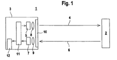
- Figure 1 shows schematically the structure of an optical sensor 1 for determining the distances of objects 2 within a monitoring area.
- the optical sensor 1 integrated in a housing 3 has a transmitter 5 emitting transmit light beams 4 and a receiver 7 receiving receive light beams 6.
- the transmitter 5 is formed by a laser diode, the receiver 7 by an avalanche photodiode.
- the transmitter 5 is followed by a transmitting optics 8 for beam shaping.
- the received light beams 6 are guided by means of a receiving optical system 9 on the receiver 7.
- the transmitted light beams 4 are guided through an exit window 10 in the front wall of the housing 3 in the surveillance area and meet an object 2.
- the reflected back to the object 2 received light beams 6 are guided through the exit window 10 to the receiver 7.
- the distance measurement takes place according to the phase measurement principle.
- a signal processing unit 11 is integrated in the optical sensor 1.
- the transmission light beams 4 are impressed with an amplitude modulation having at least one modulation frequency.
- the received light beams 6 reflected back from the object 2 to the receiver 7 have the same amplitude modulation, however, the received light beams 6 registered at the receiver 7 are phase shifted from the optical sensor 1 to the object 2 with respect to the transmitted light beams 4 emitted from the transmitter 5 by a phase shift ⁇ . From this phase shift ⁇ takes place in the signal processing unit 11, the determination of the object distance.
- the distance values thus determined are output via an output 12.
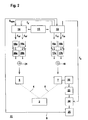
- FIG. 2 shows the structure of the signal processing unit 11 of the optical sensor 1 according to FIG. 1.
- the signal processing unit 11 has two logic units formed from digital components, each of which comprises a divider 13, 14.
- the dividers 13, 14 are connected to an oscillator 15, which is designed as a quartz oscillator. With the oscillator 15, a frequency signal with the fundamental frequency f 0 is generated.
- two bandpass filters 16a, 16b are arranged downstream of the first divider 13, with each amplifier 16a, 16b being followed by an amplifier 17a, 17b.
- the outputs of the amplifiers 17a, 17b are fed to the receiver 7 of the optical sensor 1 via a first summing element 18.
- the second divider 14 two bandpass filters 19a, 19b downstream, each bandpass filter 19a, 19b, an amplifier 20a, 20b is arranged downstream.
- the outputs of the amplifiers 20a, 20b are fed to the transmitter 5 of the optical sensor 1 via a second summing element 21.
- the logic units can also form a structural unit.
- the output signals at the output of the receiver 7 are fed via an additional bandpass filter 22 and an amplifier 23 to an analog-to-digital converter 24.
- This is connected to a microprocessor 25, which forms an evaluation unit, in which from the output signals of the receiver 7, the respective object distance is calculated.
- the transmitted light beams 4 of the transmitter 5 are cyclically successively amplitude modulated with two frequencies f 1 and f 2 '.
- the transmitter 5 can also be amplitude-modulated with only one frequency f 1 '.
- the frequencies f 10 and f 20 are successively generated by dividing the frequency.
- the thus generated frequency f 10 and its harmonics are supplied to the band-pass filter 16a.
- the fundamental or a harmonic of the frequency f 10 is filtered out, so that the pending at the output of the band filter 16 a frequency f 1 of the frequency f 10 or an integer multiple thereof.
- the frequency f 2 is obtained by means of the bandpass filter 16b from the frequency f 20 .
- the second frequency pair, the frequencies f 2 , f 2 'according to the relationship f 2 ' f 2 - .DELTA.f offset by the difference frequency .DELTA.f against each other.
- the frequency shift of f 1 'and f 2 ' with respect to f 1 and f 2 takes place digitally in that a generated by division of the fundamental frequency f 0 in the divider 13 frequency f v is supplied to the divider 14.
- this signal serves as a clock for forwarding the frequency signal f 10 or f 20 between discrete phase positions, which are determined by edges of the frequency signal f 0 , from which then shifted with respect to .DELTA.f, slightly low-frequency signals f 10 ', f 20 ' are generated.
- the transmitted light beams 4 are amplitude-modulated with the frequency f 1 '.
- the frequency signal f 1 is supplied as a clock to the receiver 7.
- the reflected from the object 2 received light beams 6 are amplitude modulated as the transmitted light beams 4 with the frequency f 1 '. Due to the light transit time of the transmitted light beams 4 and the received light beams 6 between the optical sensor 1 and the object 2, the received light beams 6 have a phase shift ⁇ .
- the receiver 7 there is a mixing of the clock with the frequency f 1 and the received signal generated by the received light beams 6 the frequency f 1 ', so that the output signal at the output of the receiver 7, which has the phase difference ⁇ containing the distance information, is a periodic signal with the difference frequency .DELTA.f.
- the second distance measurement is carried out with the frequency pair f 2 , f 2 ', wherein also here a phase shift ⁇ containing periodic output signal with the difference frequency .DELTA.f is obtained.
- FIGS. 3 and 4 show the evaluation method for determining the phase shift ⁇ from the periodic output signal.
- the output signal A shown in FIG. 3 has a sinusoidal profile in the present case.
- the output signal A has a phase shift denoted by ⁇ with respect to a reference point, which is determined, for example, by a calibration measurement against a reference target before the optical sensor 1 is put into operation.
- the phase shift ⁇ of the output signal A is determined, after which the respective distance value is calculated from the phase shift ⁇ and output via the output 12.
- Figure 4 shows schematically the sampling of a period of the sinusoidal output signal A with a sampling group of four samples.
- the right diagram shows the time course of the sinusoidal output signal A with the phase shift ⁇ .
- e - j ⁇ where j ⁇ -1.
- phase shift ⁇ In order to obtain the phase shift ⁇ from the sinusoidal profile of the output signal A, this relationship is utilized and accordingly four samples offset by 90 ° each are defined with which the phase shift ⁇ can be determined. As shown in FIG. 4 (right-hand diagram), the four sampled values are defined by the amplitude values of the output signal U (0), U (1), U (2), U (3), wherein these amplitude values are each offset by 90 ° relative to one another Period of the output signal A lie.
- the formation of the multiple sample of the output signal A is defined by a sampling unit, which in the present case from the analog-to-digital converter 24 exists.
- the sampling rate of the output signal A is predetermined by a sampling frequency f A.
- This sampling frequency f A is generated in the divider 13 by dividing the fundamental frequency f 0 and fed to the analog-to-digital converter 24. Since the sampling frequency f A, like the remaining frequencies f 1 , f 2 , f 1 ', f 2 ', is derived from the fundamental frequency f 0 , a defined, constant frequency ratio exists between all frequencies.
- the microprocessor 25 not only forms the evaluation unit for determining the distance values, but also a trigger unit for controlling the scanning unit and the logic units, in particular the dividers 13, 14.
- a start signal S for activating the dividers 13, 14 and the analog-to-digital converter 24 is generated in the microprocessor 25 before each individual distance measurement with the frequency pair f 1 , f 1 'or f 2 , f 2 '.
- the start signal S generates a defined time reference point both for the frequencies f 1 , f 1 'or f 2 , f 2 ' and for the sampling frequency f A. Since the same time reference point as for the frequencies f 1 , f 1 ', f 2 , f 2 ' is thus obtained for driving the transmitter 5 or the receiver 7 for the sampling of the output signal A of the receiver 7, there is no need for additional distance measurements Reference measurement be performed more.
- a one-time calibration measurement for defining a reference point for the phase shift ⁇ of the output signal A is rather sufficient.
- Figure 1 S start signal is supplied to the first divider 13.
- the activation of the individual components of the logic units and of the scanning units performed thereon is illustrated in FIG.
- the dividers 13, 14 and the analog-to-digital converter 24 are deactivated.
- the start signal S which is generated in the microcontroller and is read into the divider 13 at the time t 0 , is asynchronous to the fundamental frequency f 0 of the oscillator 15.
- the asynchronous start signal S follows the start signal S following the asynchronous start signal rising edge of the fundamental frequency f 0 generates a synchronous start signal S sync , with which the divider 13 is activated.
- the synchronous start signal S sync is, as shown in Figure 2, read as an activation signal from the divider 13 in the divider 14.
- This start signal which is synchronous to the fundamental frequency f 0 , could in principle already serve as a time reference point for the frequency pairs f 1 , f 1 'or f 2 , f 2 '.
- an internal start signal S int is activated in each divider 13, 14 with the rising edge of the fundamental frequency f 0 following the activation of the synchronous start signal S sync , as shown in FIG.
- t 1 ' the time of activation of the internal start signal S int is denoted by t 1 '.
- This time which is identical for both divisors 13, 14, since each of the fundamental frequency f 0 is activated, forms the temporal reference point for the frequency pairs f 1 , f 1 'and f 2 , f 2 ' and for the sampling frequency f A ,
- the activation of the analog-to-digital converter 24 has a defined relation to the internal start signal S int , since the time t 3 is delayed by a whole number of periods of the fundamental frequency f 0 with respect to the internal start signal S int (time t 1 ') ,
- the time t 3 is defined by a rising edge of the fundamental frequency f 0 , the time t 3 is a whole number of periods of the fundamental frequency f 0 offset to the time t 1 ', which defines the activation of the divider 13, 14.
- the dividers 13, 14 and the scanning unit are preferably deactivated again via the microcontroller.
- the two individual measurements are used to determine a current distance value.
- the measuring cycle with the aforementioned individual measurements is then repeated periodically.
Landscapes
- Physics & Mathematics (AREA)
- Electromagnetism (AREA)
- Engineering & Computer Science (AREA)
- Computer Networks & Wireless Communication (AREA)
- General Physics & Mathematics (AREA)
- Radar, Positioning & Navigation (AREA)
- Remote Sensing (AREA)
- Optical Radar Systems And Details Thereof (AREA)
Description
Die Erfindung betrifft einen optischen Sensor.The invention relates to an optical sensor.
Derartige optische Sensoren dienen zur Bestimmung von Distanzen von Objekten in einem Überwachungsbereich. Die Distanzbestimmung erfolgt dabei nach der Phasendifferenzmethode. Der optische Sensor weist hierzu einen Sendelichtstrahlen emittierenden Sender und einen Empfangslichtstrahlen empfangenden Empfänger auf. Zur Durchführung der Phasenmessung wird im einfachsten Fall den Sendelichtstrahlen eine Amplitudenmodulation mit einer einzelnen Frequenz aufgeprägt. Die von einem Objekt reflektierten Empfangslichtstrahlen weisen eine entsprechende Amplitudenmodulation auf, jedoch ist diese entsprechend der Lichtlaufzeit von dem optischen Sensor zum Objekt und zurück zum optischen Sensor phasenversetzt zur Amplitudenmodulation der Sendelichtstrahlen. In einer Signalverarbeitungseinheit wird die Phasendifferenz der Sendelichtstrahlen und der Empfangslichtstrahlen bestimmt. Aus dieser Phasendifferenz wird dann die Distanz des Objektes zum optischen Sensor berechnet.Such optical sensors are used to determine distances of objects in a surveillance area. The distance determination is carried out according to the phase difference method. For this purpose, the optical sensor has a transmitting light beam emitting transmitter and a receiving light beam receiving receiver. To carry out the phase measurement, an amplitude modulation with a single frequency is impressed on the transmitted light beams in the simplest case. The received light beams reflected from an object have a corresponding amplitude modulation, but this is in phase offset from the optical sensor to the object and back to the optical sensor for amplitude modulation of the transmitted light beams according to the light transit time. In a signal processing unit, the phase difference of the transmitted light beams and the received light beams is determined. From this phase difference, the distance of the object to the optical sensor is then calculated.
Aus der DE 198 11 550 A1 ist ein derartiger nach der Phasendifferenzmethode arbeitender optischer Sensor bekannt. Dieser optische Sensor weist eine aus digitalen Schaltungskomponenten bestehende Schaltungsanordnung zur Erzeugung von Frequenzsignalen auf, die zur Durchführung der Phasenmessung benötigt werden.From DE 198 11 550 A1, such an optical sensor operating according to the phase difference method is known. This optical sensor has an existing digital circuit components circuit arrangement for generating frequency signals that are needed to perform the phase measurement.
Dabei umfasst die Schaltungsanordnung einen eine Grundfrequenz f0 generierenden Oszillator. Dieser ist an zwei Logikeinheiten angeschlossen, die jeweils im Wesentlichen aus einem Teiler, einem Filter und einem Verstärker bestehen.In this case, the circuit arrangement comprises an oscillator generating a fundamental frequency f 0 . This is connected to two logic units, each consisting essentially of a divider, a filter and an amplifier.
In einem ersten Teiler wird durch Teilen der Grundfrequenz f0 eine Frequenz f1 generiert, die als Taktsignal dem Empfänger zugeführt wird, welcher von einer Avalanche-Photodiode gebildet ist.In a first divider, a frequency f 1 is generated by dividing the fundamental frequency f 0 , which is fed as a clock signal to the receiver, which is formed by an avalanche photodiode.
In einem zweiten Teiler wird durch Teilen der Grundfrequenz f0 eine Frequenz f1' erzeugt, welche f1' = f1 - Δf beträgt. Mit dieser Frequenz f1' werden die Sendelichtstrahlen des Senders amplitudenmoduliert.In a second divider, by dividing the fundamental frequency f 0, a frequency f 1 'is generated which is f 1 ' = f 1 -Δf. With this frequency f 1 ', the transmitted light beams of the transmitter are amplitude-modulated.
Die Frequenzen f1 und f1' liegen typischerweise im MHz-Bereich, während die Differenzfrequenz Δf, um welche sich die Frequenzen f1 und f1' unterscheiden, typischerweise im kHz-Bereich liegt.The frequencies f 1 and f 1 'are typically in the MHz range while the difference frequency .DELTA.f to which the frequencies f 1 and f 1' are different, typically in the kilohertz range.
Die Frequenz f1' wird aus der Frequenz f1 abgeleitet, in dem das Frequenzsignal f1 mit einer vorgegebenen Taktfrequenz zwischen diskreten Phasenlagen, die durch Flanken des Frequenzsignals mit der Grundfrequenz f0 bestimmt sind, weiter geschaltet wird.The frequency f 1 'is derived from the frequency f 1 , in which the frequency signal f 1 with a predetermined clock frequency between discrete phase positions, which are determined by edges of the frequency signal at the fundamental frequency f 0 , is switched further.
In dem Empfänger erfolgt eine Mischung der Frequenzsignale f1, f1' dadurch, dass die mit der Frequenz f1' amplitudenmodulierten, durch die Empfangslichtstrahlen generierten Empfangssignale mit der Taktfrequenz f1 überlagert werden.In the receiver, a mixing of the frequency signals f 1 , f 1 'takes place in that the received signals which are amplitude-modulated with the frequency f 1 ' and which are generated by the received light beams are superposed with the clock frequency f 1 .
Das dadurch am Ausgang des Empfängers generierte periodische Ausgangssignal mit der Frequenz Δf enthält die Phasenverschiebung zwischen den Sendelichtstrahlen und den Empfangslichtstrahlen und damit die Information über die zu bestimmende Objektdistanz.The thereby generated at the output of the receiver periodic output signal with the frequency .DELTA.f contains the phase shift between the transmitted light beams and the received light beams and thus the information about the object distance to be determined.
Zur Bestimmung der Phasendifferenz wird das Ausgangssignal mit einer bestimmten Abtastfrequenz fA abgetastet. Hierzu ist ein Mikroprozessor vorgesehen, welcher einen Analog-Digital-Wandler mit der Abtastfrequenz fA ansteuert. Die dabei generierten Abtastwerte werden in dem Mikroprozessor zur Ermittlung der Objektdistanz ausgewertet.To determine the phase difference, the output signal is sampled at a certain sampling frequency f A. For this purpose, a microprocessor is provided, which drives an analog-to-digital converter with the sampling frequency f A. The generated samples are evaluated in the microprocessor to determine the object distance.
Die mit dem Sender und Empfänger durchgeführten Distanzmessungen werden jeweils auf eine Referenzmessung bezogen, wobei hierzu die Sendelichtstrahlen über eine Referenzstrecke zum Empfänger geführt sind.The distance measurements made with the transmitter and receiver are each related to a reference measurement, for which purpose the transmitted light beams are guided over a reference path to the receiver.
Ein wesentlicher Vorteil des optischen Sensors gemäß der DE 198 11 550 A1 besteht darin, dass die einzelnen Frequenzsignale aus einem einzigen Oszillator durch Teilen der Grundfrequenz f0 dieses Oszillators digital abgeleitet werden. Dadurch wird eine genaue Distanzmessung ermöglicht.A significant advantage of the optical sensor according to DE 198 11 550 A1 is that the individual frequency signals are derived digitally from a single oscillator by dividing the fundamental frequency f 0 of this oscillator. This allows an accurate distance measurement.
Nachteilig hierbei ist jedoch der hohe konstruktive Aufwand des optischen Sensors zur Durchführung der Distanzmessung. Insbesondere erfordert die fortlaufend für jede Distanzmessung durchzuführende Referenzmessung einen unerwünscht hohen Aufwand.The disadvantage here, however, is the high design complexity of the optical sensor for carrying out the distance measurement. In particular, the reference measurement to be carried out continuously for each distance measurement requires an undesirably high outlay.
Der Erfindung liegt die Aufgabe zugrunde einen optischen Sensor der eingangs genannten Art derart weiterzubilden, dass mit diesem bei möglichst geringem konstruktiven Aufwand eine genaue Distanzbestimmung ermöglicht wird.The invention has the object of developing an optical sensor of the type mentioned in such a way that with this with the least possible design effort an accurate distance determination is possible.
Zur Lösung dieser Aufgabe sind die Merkmale des Anspruchs 1 vorgesehen. Vorteilhafte Ausführungsformen und zweckmäßige Weiterbildungen der Erfindung sind in den Unteransprüchen beschrieben.To solve this problem, the features of
Der erfindungsgemäße optische Sensor dient zur Bestimmung von Distanzen von Objekten innerhalb eines Überwachungsbereichs weist einen Sendelichtstrahlen emittierenden Sender und einer diesem zugeordneten ersten Logikeinheit zur Generierung wenigstens einer Frequenz f1' auf, mit welcher die Sendelichtstrahlen amplitudenmoduliert sind. Ebenso beinhaltet der erfindungsgemäße optische Sensor einen Empfangslichtstrahlen empfangenden Empfänger und einer diesem zugeordneten zweiten Logikeinheit zur Generierung wenigstens einer zweiten Frequenz f1, welche bezüglich der Frequenz f1' um eine Differenzfrequenz Δf verschoben ist. Diese zweite Frequenz f1 ist als Taktsignal dem Empfänger zugeführt, so dass am Ausgang des Empfängers durch Mischen der Frequenzen f1 und f1' ein periodisches Ausgangssignal mit der Differenzfrequenz Δf und mit einer ein Maß für die Objektdistanz darstellenden Phasenverschiebung generiert wird. Weiterhin weist der erfindungsgemäße optische Sensor eine Abtasteinheit zur Abtastung des Ausgangssignals mit einer Abtastfrequenz fA auf. Ebenso beinhaltet der erfindungsgemäße optische Sensor eine Auswerteeinheit zur Berechnung der Objektdistanz aus der durch Abtastung des Ausgangssignals ermittelten Phasenverschiebung. Eine Triggereinheit dient zur Generierung eines Startsignals für die Logikeinheiten und die Abtasteinheiten, wobei mit dem Startsignal ein gemeinsamer zeitlicher Bezugspunkt für die Frequenzen fA, f1 und f1' generiert wird.The optical sensor according to the invention is used to determine distances of objects within a monitoring area has a transmitting light beam emitting transmitter and a first logic unit associated therewith for generating at least one frequency f 1 ', with which the transmitted light beams are amplitude modulated. Likewise, the optical sensor according to the invention includes a receiving light beam receiving receiver and a second logic unit associated therewith for generating at least a second frequency f 1 , which is shifted with respect to the frequency f 1 'by a difference frequency .DELTA.f. This second frequency f 1 is as a clock signal the Supplied receiver so that at the output of the receiver by mixing the frequencies f 1 and f 1 ', a periodic output signal with the difference frequency .DELTA.f and with a measure of the object distance representing phase shift is generated. Furthermore, the optical sensor according to the invention has a scanning unit for sampling the output signal at a sampling frequency f A. Likewise, the optical sensor according to the invention includes an evaluation unit for calculating the object distance from the phase shift determined by sampling the output signal. A trigger unit is used to generate a start signal for the logic units and the scanning units, with the start signal a common time reference point for the frequencies f A , f 1 and f 1 'is generated.
Ein wesentlicher Vorteil des erfindungsgemäßen optischen Sensors besteht darin, dass durch den gemeinsamen Bezug der Frequenzsignale der Logikeinheiten und der Abtasteinheiten eine fortlaufende Referenzmessung zur Referenzierung der einzelnen aktuell ermittelten Distanzwerte entfallen kann.A significant advantage of the optical sensor according to the invention is that a continuous reference measurement for the referencing of the individual currently determined distance values can be omitted by the common reference of the frequency signals of the logic units and the scanning units.
Um einen eindeutigen Referenzpunkt der in der Auswerteeinheit ermittelten Phasenverschiebungen zu der Objektdistanz herzustellen, braucht lediglich eine Kalibrierungsmessung mit dem optischen Sensor gegen ein vorgegebenes Referenzziel durchgeführt werden. Zweckmäßigerweise kann die Kalibrierungsmessung vor Inbetriebnahme des optischen Sensors durchgeführt werden. Zur Kompensation von Störeinflüssen wie zum Beispiel thermischem Driften von Bauelementen kann die Kalibrierungsmessung in größeren Zeitabständen wiederholt werden.In order to produce a unique reference point of the phase shifts in the evaluation unit determined to the object distance, only a calibration measurement with the optical sensor against a predetermined reference target needs to be performed. The calibration measurement can expediently be carried out before the optical sensor is put into operation. To compensate for interferences, such as thermal drift of components, the calibration measurement can be repeated at longer intervals.
Da für die einzelnen Distanzmessungen bei dem erfindungsgemäßen optischen Sensor keine Referenzmessungen durchgeführt werden müssen, wird eine erhebliche Reduzierung des konstruktiven Aufwandes des optischen Sensors erzielt. Außerdem werden die Messzeiten des optischen Sensors bei der Distanzbestimmung erheblich verkürzt.Since no reference measurements have to be carried out for the individual distance measurements in the case of the optical sensor according to the invention, a considerable reduction of the design complexity of the optical sensor is achieved. In addition, the measuring times of the optical sensor in the distance determination are considerably shortened.
Die Erfindung wird im Nachstehenden anhand der Zeichnungen erläutert. Es zeigen:
- Figur 1:
- Schematische Darstellung des erfindungsgemäßen optischen Sensors.
- Figur 2:
- Blockschaltbild der Signalverarbeitungseinheit des optischen Sensors gemäß
Figur 1. - Figur 3:
- Verlauf des in der Signalverarbeitungseinheit generierten sinusförmigen Ausgangssignals und eines Referenzsignals.
- Figur 4:
- Schematische Darstellung der Ermittlung der Phasenverschiebung des Ausgangssignals gemäß
Figur 3 aus einer Anzahl von Abtastwerten. - Figur 5:
- Zeitlicher Verlauf der in der Signalverarbeitungseinheit gemäß
Figur 2 generierten Frequenzsignale.
- FIG. 1:
- Schematic representation of the optical sensor according to the invention.
- FIG. 2:
- Block diagram of the signal processing unit of the optical sensor according to Figure 1.
- FIG. 3:
- Course of the generated in the signal processing unit sinusoidal output signal and a reference signal.
- FIG. 4:
- Schematic representation of the determination of the phase shift of the output signal according to Figure 3 from a number of samples.
- FIG. 5:
- Time course of the frequency signals generated in the signal processing unit according to FIG.
Figur 1 zeigt schematisch den Aufbau eines optischen Sensors 1 zur Bestimmung der Distanzen von Objekten 2 innerhalb eines Überwachungsbereichs. Der in einem Gehäuse 3 integrierte optische Sensor 1 weist einen Sendelichtstrahlen 4 emittierenden Sender 5 und einen Empfangslichtstrahlen 6 empfangenden Empfänger 7 auf. Der Sender 5 ist von einer Laserdiode, der Empfänger 7 von einer Avalanche-Photodiode gebildet. Dem Sender 5 ist zur Strahlformung eine Sendeoptik 8 nachgeordnet. Die Empfangslichtstrahlen 6 werden mittels einer Empfangsoptik 9 auf den Empfänger 7 geführt. Die Sendelichtstrahlen 4 werden durch ein Austrittsfenster 10 in der Frontwand des Gehäuses 3 in den Überwachungsbereich geführt und treffen auf ein Objekt 2. Die am Objekt 2 zurückreflektierten Empfangslichtstrahlen 6 werden durch das Austrittsfenster 10 zum Empfänger 7 geführt.Figure 1 shows schematically the structure of an
Die Distanzmessung erfolgt nach dem Phasenmessprinzip. Zur Durchführung der Distanzmessung ist in dem optischen Sensor 1 eine Signalverarbeitungseinheit 11 integriert. Mittels dieser wird den Sendelichtstrahlen 4 eine Amplitudenmodulation mit wenigstens einer Modulationsfrequenz aufgeprägt. Die vom Objekt 2 zum Empfänger 7 zurückreflektierten Empfangslichtstrahlen 6 weisen dieselbe Amplitudenmodulation auf, jedoch sind die am Empfänger 7 registrierten Empfangslichtstrahlen 6 bezüglich der vom Sender 5 emittierten Sendelichtstrahlen 4 um eine Phasenverschiebung ϕ entsprechend der Lichtlaufzeit vom optischen Sensor 1 zum Objekt 2 phasenverschoben. Aus dieser Phasenverschiebung ϕ erfolgt in der Signalverarbeitungseinheit 11 die Bestimmung der Objektdistanz. Die so ermittelten Distanzwerte werden über einen Ausgang 12 ausgegeben.The distance measurement takes place according to the phase measurement principle. To carry out the distance measurement, a
Figur 2 zeigt den Aufbau der Signalverarbeitungseinheit 11 des optischen Sensors 1 gemäß Figur 1. Die Signalverarbeitungseinheit 11 weist zwei aus digitalen Bauelementen gebildete Logikeinheiten auf, welche jeweils einen Teiler 13, 14 umfassen. Die Teiler 13, 14 sind an einen Oszillator 15 angeschlossen, der als Quarzoszillator ausgebildet ist. Mit dem Oszillator 15 wird ein Frequenzsignal mit der Grundfrequenz f0 generiert.FIG. 2 shows the structure of the
Im vorliegenden Fall sind dem ersten Teiler 13 zwei Bandpassfilter 16a, 16b nachgeordnet, wobei jedem Bandpassfilter 16a, 16b ein Verstärker 17a, 17b nachgeordnet ist. Die Ausgänge der Verstärker 17a, 17b sind über ein erstes Summierglied 18 auf den Empfänger 7 des optischen Sensors 1 geführt.In the present case, two
Entsprechend sind dem zweiten Teiler 14 zwei Bandpassfilter 19a, 19b nachgeordnet, wobei jedem Bandpassfilter 19a, 19b ein Verstärker 20a, 20b nachgeordnet ist. Die Ausgänge der Verstärker 20a, 20b sind über ein zweites Summierglied 21 auf den Sender 5 des optischen Sensors 1 geführt.Accordingly, the
In Abwandlung zur Ausführungsform gemäß Figur 2 können die Logikeinheiten auch eine Baueinheit bilden.In a modification of the embodiment according to FIG. 2, the logic units can also form a structural unit.
Die Ausgangssignale am Ausgang des Empfängers 7 werden über ein weiteres Bandpassfilter 22 und einen Verstärker 23 einem Analog-Digital-Wandler 24 zugeführt. Dieser ist an einen Mikroprozessor 25 angeschlossen, der eine Auswerteeinheit bildet, in welcher aus den Ausgangssignalen des Empfängers 7 die jeweilige Objektdistanz berechnet wird.The output signals at the output of the
Zur Durchführung der Phasenmessung werden die Sendelichtstrahlen 4 des Senders 5 zyklisch nacheinander mit zwei Frequenzen f1 und f2' amplitudenmoduliert. Prinzipiell kann der Sender 5 auch nur mit einer Frequenz f1' amplitudenmoduliert werden. Durch die Verwendung von zwei oder mehreren Frequenzen zur Modulation der Sendelichtstrahlen 4 kann der Eindeutigkeitsbereich der mit dem optischen Sensor 1 gemessenen Phasendifferenz zwischen Sendelichtstrahlen 4 und Empfangslichtstrahlen 6 und damit der erfassbare Distanzbereich erheblich gesteigert werden.To carry out the phase measurement, the transmitted light beams 4 of the
Sowohl die mittels des Teilers 13 und dessen nachgeordneten Komponenten der ersten Logikeinheit generierten Frequenzen f1, f2 als auch die mittels des Teilers 14 und dessen nachgeordneten Komponenten der zweiten Logikeinheit generierten Frequenzen f1, f2 sind von der Grundfrequenz f0 des Oszillators 15 abgeleitet, so dass zwischen diesen eine fest vorgegebene Beziehung besteht.Both generated by means of the
In dem Teiler 13 werden durch Teilung der Frequenz nacheinander die Frequenzen f10 und f20 generiert. Die so erzeugte Frequenz f10 sowie deren Oberschwingungen werden dem Bandpassfilter 16a zugeführt. Dort wird die Grundschwingung oder eine Oberschwingung der Frequenz f10 ausgefiltert, so dass die am Ausgang des Bandfilters 16a anstehende Frequenz f1 der Frequenz f10 oder einem ganzzahligen Vielfachen hiervon entspricht. Entsprechend wird mittels des Bandpassfilters 16b aus der Frequenz f20 die Frequenz f2 gewonnen.In the
In entsprechender Weise werden durch Teilung der Grundfrequenz f0 im Teiler 14 die Frequenzen f10' und f20' erzeugt, aus welchen in den Bandpassfiltern 19a, 19b die Frequenzen f1' und f2' gewonnen werden.In a corresponding manner, by dividing the fundamental frequency f 0 in the
Dabei sind als erstes Frequenzpaar die Frequenzen f1, f1' gemäß der Beziehung f1' = f1 - Δf um eine Differenzfrequenz Δf gegeneinander verschoben. Entsprechend sind als zweites Frequenzpaar die Frequenzen f2, f2' gemäß der Beziehung f2' = f2 - Δf um die Differenzfrequenz Δf gegeneinander verschoben.In this case, the frequencies f 1 , f 1 'are shifted as a first frequency pair according to the relationship f 1 ' = f 1 - .DELTA.f to each other by a difference frequency .DELTA.f. Accordingly, the second frequency pair, the frequencies f 2 , f 2 'according to the relationship f 2 ' = f 2 - .DELTA.f offset by the difference frequency .DELTA.f against each other.
Die Frequenzverschiebung von f1' beziehungsweise f2' gegenüber f1 beziehungsweise f2 erfolgt auf digitalem Weg dadurch, dass eine durch Teilung der Grundfrequenz f0 im Teiler 13 generierte Frequenz fv dem Teiler 14 zugeführt wird. Entsprechend dem in der DE 198 11 550 C2 beschriebenen Verfahren dient dieses Signal als Takt zur Weiterschaltung des Frequenzsignals f10 beziehungsweise f20 zwischen diskreten Phasenlagen, die durch Flanken des Frequenzsignals f0 bestimmt sind, woraus dann die bezüglich um Δf verschobenen, etwas niederfrequenten Frequenzsignale f10', f20' generiert werden.The frequency shift of f 1 'and f 2 ' with respect to f 1 and f 2 takes place digitally in that a generated by division of the fundamental frequency f 0 in the
Da die Frequenzen f10, f20 und über fv auch f10' und f20' jeweils einen festen Bezug zur Grundfrequenz f0 aufweisen, weisen diese Frequenzen fest definierte, konstante Frequenzverhältnisse zueinander aufSince the frequencies f 10 , f 20 and over f v also f 10 'and f 20 ' each have a fixed reference to the fundamental frequency f 0 , these frequencies have fixed, constant frequency ratios to each other
Zur Durchführung einer ersten Distanzmessung werden die Sendelichtstrahlen 4 mit der Frequenz f1' amplitudenmoduliert. Zeitgleich wird das Frequenzsignal f1 als Takt dem Empfänger 7 zugeführt. Die vom Objekt 2 reflektierten Empfangslichtstrahlen 6 sind wie die Sendelichtstrahlen 4 mit der Frequenz f1' amplitudenmoduliert. Durch die Lichtlaufzeit der Sendelichtstrahlen 4 beziehungsweise der Empfangslichtstrahlen 6 zwischen dem optischen Sensor 1 und dem Objekt 2 weisen die Empfangslichtstrahlen 6 eine Phasenverschiebung ϕ auf. In dem Empfänger 7 erfolgt eine Mischung des Taktes mit der Frequenz f1 und dem durch die Empfangslichtstrahlen 6 generierten Empfangssignal mit der Frequenz f1', so dass das Ausgangssignal am Ausgang des Empfängers 7, welches die die Distanzinformation enthaltende Phasenverschiebung ϕ aufweist, ein periodisches Signal mit der Differenzfrequenz Δf ist.To carry out a first distance measurement, the transmitted light beams 4 are amplitude-modulated with the frequency f 1 '. At the same time, the frequency signal f 1 is supplied as a clock to the
Die zweite Distanzmessung erfolgt mit dem Frequenzpaar f2, f2', wobei auch hier ein die Phasenverschiebung ϕ enthaltendes periodisches Ausgangssignal mit der Differenzfrequenz Δf erhalten wird.The second distance measurement is carried out with the frequency pair f 2 , f 2 ', wherein also here a phase shift φ containing periodic output signal with the difference frequency .DELTA.f is obtained.
Die Figuren 3 und 4 zeigen das Auswerteverfahren zur Bestimmung der Phasenverschiebung ϕ aus dem periodischen Ausgangssignal. Das in Figur 3 dargestellte, mit A bezeichnete Ausgangssignal weist im vorliegenden Fall einen sinusförmigen Verlauf auf.FIGS. 3 and 4 show the evaluation method for determining the phase shift φ from the periodic output signal. The output signal A shown in FIG. 3 has a sinusoidal profile in the present case.
Das Ausgangssignal A weist eine mit ϕ bezeichnete Phasenverschiebung bezüglich einem Referenzpunkt auf, welcher beispielsweise durch eine Kalibrierungsmessung gegen ein Referenzziel vor Inbetriebnahme des optischen Sensors 1 festgelegt wird.The output signal A has a phase shift denoted by φ with respect to a reference point, which is determined, for example, by a calibration measurement against a reference target before the
Durch Mehrfachabtastung des Amplitudenverlaufs des sinusförmigen Ausgangssignals A wird die Phasenverschiebung ϕ des Ausgangssignals A ermittelt, wonach aus der Phasenverschiebung ϕ der jeweilige Distanzwert errechnet und über den Ausgang 12 ausgegeben wird.By multiple sampling of the amplitude curve of the sinusoidal output signal A, the phase shift φ of the output signal A is determined, after which the respective distance value is calculated from the phase shift φ and output via the
Figur 4 zeigt schematisch die Abtastung einer Periode des sinusförmigen Ausgangssignals A mit einer Abtastgruppe von vier Abtastwerten. Das rechte Diagramm zeigt den zeitlichen Verlauf des sinusförmigen Ausgangssignals A mit der Phasenverschiebung ϕ. Das linke Diagramm stellt das entsprechende Zeigerdiagramm für das Ausgangssignal A in der komplexen Ebene dar, wobei Im den Imaginärteil und Re den Realteil der entsprechenden komplexen Funktion für das Ausgangssignal A bildet. Da das sinusförmige Ausgangssignal A um die Phasenverschiebung ϕ bezüglich des Nullpunkts als Bezugspunkt verschoben ist, ergibt sich durch dieselbe Phasenverschiebung ϕ in der komplexen Funktion Z im Zeigerdiagramm gemäß der Beziehung ![]()
wobei j = √-1.Figure 4 shows schematically the sampling of a period of the sinusoidal output signal A with a sampling group of four samples. The right diagram shows the time course of the sinusoidal output signal A with the phase shift φ. The left-hand diagram represents the corresponding phasor diagram for the output signal A in the complex plane, Im forming the imaginary part and Re the real part of the corresponding complex function for the output signal A. Since the sinusoidal output signal A is shifted by the phase shift φ with respect to the zero point as a reference point is given by the same phase shift φ in the complex function Z in the vector diagram according to the relationship ![]()
where j = √-1.
Dementsprechend ergibt sich die Phasenverschiebung ϕ gemäß der Beziehung 
Um aus dem sinusförmigen Verlauf des Ausgangssignals A die Phasenverschiebung ϕ zu erhalten, wird diese Beziehung ausgenutzt und dementsprechend werden vier um jeweils 90° versetzte Abtastwerte definiert, mit welchen die Phasenverschiebung ϕ ermittelt werden kann. Wie in Figur 4 (rechtes Diagramm) dargestellt sind die vier Abtastwerte durch die Amplitudenwerte des Ausgangssignals U(0), U(1), U(2), U(3) definiert, wobei diese Amplitudenwerte jeweils um 90° zueinander versetzt innerhalb einer Periode des Ausgangssignals A liegen.In order to obtain the phase shift φ from the sinusoidal profile of the output signal A, this relationship is utilized and accordingly four samples offset by 90 ° each are defined with which the phase shift φ can be determined. As shown in FIG. 4 (right-hand diagram), the four sampled values are defined by the amplitude values of the output signal U (0), U (1), U (2), U (3), wherein these amplitude values are each offset by 90 ° relative to one another Period of the output signal A lie.
Wie aus dem Vergleich mit dem Zeigerdiagramm in Figur 4 folgt, stellt die Differenz D1 =½ (U(1) - U(3)) den Realteil und die Differenz D2 = ½ ( U(0) - U(2)) den Imaginärteil der komplexen Funktion des Zeigerdiagramms dar.As follows from the comparison with the phasor diagram in Figure 4, the difference D 1 = ½ (U (1) - U (3)) represents the real part and the difference D 2 = ½ (U (0) - U (2)) the imaginary part of the complex function of the phasor diagram.
Dementsprechend errechnet sich die Phasendifferenz ϕ aus den Abtastwerten U(0), U(1), U(2), U(3) gemäß der Beziehung ![]()
![]()
Die Ausbildung der Mehrfachabtastung des Ausgangssignals A wird durch eine Abtasteinheit definiert, welche im vorliegenden Fall aus dem Analog-Digital-Wandler 24 besteht. Die Abtastrate des Ausgangssignal A wird durch eine Abtastfrequenz fA vorgegeben. Diese Abtastfrequenz fA wird im Teiler 13 durch Teilung der Grundfrequenz f0 generiert und in den Analog-Digital-Wandler 24 eingespeist. Da die Abtastfrequenz fA wie die übrigen Frequenzen f1, f2, f1', f2' aus der Grundfrequenz f0 abgeleitet ist, besteht zwischen allen Frequenzen ein definiertes, konstantes Frequenzverhältnis.The formation of the multiple sample of the output signal A is defined by a sampling unit, which in the present case from the analog-to-
Der Mikroprozessor 25 bildet nicht nur die Auswerteeinheit zur Bestimmung der Distanzwerte, sondern auch eine Triggereinheit zur Ansteuerung der Abtasteinheit sowie der Logikeinheiten, insbesondere der Teiler 13, 14.The
Hierzu wird vor jeder Einzeldistanzmessung mit dem Frequenzpaar f1, f1' oder f2, f2' in dem Mikroprozessor 25 ein Startsignal S zur Aktivierung der Teiler 13, 14 und des Analog-Digital-Wandlers 24 generiert. Generell wird mit dem Startsignal S ein definierter zeitlicher Bezugspunkt sowohl für die Frequenzen f1, f1' beziehungsweise f2, f2' als auch für die Abtastfrequenz fA generiert. Da somit für die Abtastung des Ausgangssignals A des Empfängers 7 derselbe zeitliche Bezugspunkt wie für die Frequenzen f1, f1', f2, f2' zur Ansteuerung des Senders 5 beziehungsweise des Empfängers 7 erhalten wird, braucht für die einzelnen Distanzmessungen keine zusätzliche Referenzmessung mehr durchgeführt werden. Eine einmalige Kalibrierungsmessung zur Definition eines Referenzpunkts für die Phasenverschiebung ϕ des Ausgangssignals A ist vielmehr ausreichend.For this purpose, a start signal S for activating the
Im vorliegenden Ausführungsbeispiel wird das in Figur 1 mit S bezeichnete Startsignal dem ersten Teiler 13 zugeführt. Die darauf durchgeführte Aktivierung der einzelnen Komponenten der Logikeinheiten und der Abtasteinheiten ist in Figur 5 veranschaulicht.In the present embodiment, the designated in Figure 1 S start signal is supplied to the
Vor Generierung eines Startsignals S sind die Teiler 13, 14 und der Analog-Digital-Wandler 24 deaktiviert.Before generating a start signal S, the
Das Startsignal S, das in dem Microcontroller generiert wird und zum Zeitpunkt t0 in den Teiler 13 eingelesen wird, ist asynchron zur Grundfrequenz f0 des Oszillators 15. In dem Teiler 13 wird in Abhängigkeit des asynchronen Startsignals S mit der auf das Startsignal S folgenden steigenden Flanke der Grundfrequenz f0 ein synchrones Startsignal Ssync generiert, mit welchem der Teiler 13 aktiviert wird.The start signal S, which is generated in the microcontroller and is read into the
Das synchrone Startsignal Ssync wird, wie in Figur 2 dargestellt, als Aktivierungssignal von dem Teiler 13 in den Teiler 14 eingelesen. Dieses zur Grundfrequenz f0 synchrone Startsignal könnte prinzipiell bereits als zeitlicher Bezugspunkt für die Frequenzpaare f1, f1' bzw. f2, f2' dienen. Um jedoch Fehler durch Bauteiltoleranzen und dergleichen auszuschließen wird, wie in Figur 5 dargestellt, in jedem Teiler 13, 14 mit der auf die Aktivierung des synchronen Startsignals Ssync folgenden steigenden Flanke der Grundfrequenz f0 jeweils ein internes Startsignal Sint aktiviert.The synchronous start signal S sync is, as shown in Figure 2, read as an activation signal from the
In Figur 5 ist der Zeitpunkt der Aktivierung des internen Startsignals Sint mit t1' bezeichnet. Dieser Zeitpunkt, der für beide Teiler 13, 14 identisch ist, da der jeweils aus der Grundfrequenz f0 aktiviert ist, bildet den zeitlichen Bezugspunkt für die Frequenzpaare f1, f1' und f2, f2' sowie für die Abtastfrequenz fA.In FIG. 5, the time of activation of the internal start signal S int is denoted by t 1 '. This time, which is identical for both
Wie aus Figur 5 ersichtlich, ist der Zeitpunkt t2, bei welchem die Frequenz fv aktiviert und vom ersten Teiler 13 in den zweiten Teiler 14 eingelesen wird, um eine ganze Zahl von Perioden der Grundfrequenz f0 gegenüber dem durch das interne Startsignal Sint definierten zeitlichen Bezugspunkt t1' zeitlich verschoben. Dadurch ist ein bezüglich t1' definierter zeitlicher Bezug bei der Genenerung der bezüglich f1 verschobenen Frequenz f1' und der bezüglich f2 verschobenen Frequenz f2' gewährleistet.As can be seen from Figure 5, the time t 2, in which the frequency f v is activated and read by the
Zeitlich versetzt hierzu, zu einem Zeitpunkt t3 wird die im ersten Teiler 13 generierte Abtastfrequenz fA als weiteres Aktivierungssignal dem Analog-Digital-Wandler 24 zugeführt, wodurch dieser aktiviert ist. Auch die Aktivierung des Analog-Digital-Wandlers 24 weist einen definierten Bezug zum internen Startsignal Sint auf, da der Zeitpunkt t3 um eine ganze Anzahl von Periodendauern der Grundfrequenz f0 gegenüber dem internen Startsignal Sint (Zeitpunkt t1') verzögert ist.Time offset to this, at a time t 3 , the generated in the
Da auch der Zeitpunkt t3 durch eine steigende Flanke der Grundfrequenz f0 definiert ist, liegt der Zeitpunkt t3 um eine ganze Anzahl von Perioden der Grundfrequenz f0 versetzt zu dem Zeitpunkt t1', der die Aktivierung der Teiler 13, 14 definiert.Since the time t 3 is defined by a rising edge of the fundamental frequency f 0 , the time t 3 is a whole number of periods of the fundamental frequency f 0 offset to the time t 1 ', which defines the activation of the
Dadurch ist eine Synchronisierung der Teiler 13, 14 und der Abtasteinheit und damit der Abtastung des Ausgangssignals des Empfängers 7 gegeben. Für die dann beispielsweise mit den Frequenzen f1, f1' durchgeführte Einzelmessung ist dann ein definierter zeitlicher Bezug zur Abtastung des Ausgangssignals des Empfängers 7 gegeben. Da sämtliche Frequenzen f1, f1' und fA auf das synchrone Startsignal S eindeutig bezogen sind, muss die so durchgeführte Einzelmessung nicht auf eine Referenzmessung bezogen sein.As a result, a synchronization of the
Nach dieser Einzelmessung werden die Teiler 13, 14 und die Abtasteinheit vorzugsweise über den Microcontroller wieder deaktiviert.After this individual measurement, the
Durch ein zweites Startsignal S werden diese Komponenten wieder aktiviert und synchronisiert, worauf eine zweite Einzelmessung mit den Frequenzen f2, f2' erfolgt.By a second start signal S, these components are reactivated and synchronized, whereupon a second single measurement with the frequencies f 2 , f 2 'takes place.
Aus den beiden Einzelmessungen erfolgt die Bestimmung eines aktuellen Distanzwerts.The two individual measurements are used to determine a current distance value.
Der Messtakt mit den vorgenannten Einzelmessungen wiederholt sich dann periodisch.The measuring cycle with the aforementioned individual measurements is then repeated periodically.
- (1)(1)
- Optischer SensorOptical sensor
- (2)(2)
- Objektobject
- (3)(3)
- Gehäusecasing
- (4)(4)
- SendelichtstrahlenTransmitted light beams
- (5)(5)
- Sendertransmitter
- (6)(6)
- EmpfangslichtstrahlenReceiving light rays
- (7)(7)
- Empfängerreceiver
- (8)(8th)
- Sendeoptiktransmission optics
- (9)(9)
- Empfangsoptikreceiving optics
- (10)(10)
- Austrittsfensterexit window
- (11)(11)
- SignalverarbeitungseinheitSignal processing unit
- (12)(12)
- Ausgangoutput
- (13)(13)
- Teilerdivider
- (14)(14)
- Teilerdivider
- (15)(15)
- Oszillatoroscillator
- (16a)(16a)
- BandpassfilterBandpass filter
- (16b)(16b)
- BandpassfilterBandpass filter
- (17a)(17a)
- Verstärkeramplifier
- (17b)(17b)
- Verstärkeramplifier
- (18)(18)
- Summiergliedsumming
- (19a)(19a)
- BandpassfilterBandpass filter
- (19b)(19b)
- BandpassfilterBandpass filter
- (20a)(20a)
- Verstärkeramplifier
- (20b)(20b)
- Verstärkeramplifier
- (21)(21)
- Summiergliedsumming
- (22)(22)
- BandpassfilterBandpass filter
- (23)(23)
- Verstärkeramplifier
- (24)(24)
- Analog-Digital-WandlerAnalog to digital converter
- (25)(25)
- Mikroprozessormicroprocessor
- AA
- Ausgangssignaloutput
- D1 D 1
- Differenz RealteilDifference real part
- D2 D 2
- Differenz ImaginärteilDifference imaginary part
- f0 f 0
- Grundfrequenzfundamental frequency
- f1 f 1
- Frequenzfrequency
- f1'f 1 '
- Frequenzfrequency
- f2 f 2
- Frequenzfrequency
- f2'f 2 '
- Frequenzfrequency
- f10 f 10
- Frequenzfrequency
- f10'f 10 '
- Frequenzfrequency
- f20 f 20
- Frequenzfrequency
- f20'f 20 '
- Frequenzfrequency
- Δf.delta.f
- Differenzfrequenzdifference frequency
- fA f A
- Abtastfrequenzsampling
- fv f v
- Frequenzfrequency
- Imin the
- Imaginärteilimaginary
- Rere
- Realteilreal part
- SS
- Startsignalstart signal
- t0 t 0
- Zeitpunkttime
- t1 t 1
- Zeitpunkttime
- t2 t 2
- Zeitpunkttime
- U(0)U (0)
- Amplitudenwert des AusgangssignalsAmplitude value of the output signal
- U(1)U (1)
- Amplitudenwert des AusgangssignalsAmplitude value of the output signal
- U(2)U (2)
- Amplitudenwert des AusgangssignalsAmplitude value of the output signal
- U(3)U (3)
- Amplitudenwert des AusgangssignalsAmplitude value of the output signal
- ZZ
- komplexe Funktioncomplex function
- ϕφ
- Phasenverschiebungphase shift
Claims (18)
- Optical sensor (1) for determining distances of objects (2) within a monitoring region, with a transmitter (5) emitting transmitted light beams (4) and a first logic unit associated therewith for generating at least one frequency f1', by which the transmitted light beams (4) are modulated in amplitude, with a receiver (7) receiving received light beams (6) and a second logic unit associated therewith for generating at least one second frequency f1, which is displaced with respect to the frequency f1, by a difference frequency Δf and which is fed as a clock signal to the receiver (7) so that a periodic output signal (A) with a difference frequency Δf and with a phase displacement (ϕ) representing a measure for the object distance is generated at the output of the receiver (7) by mixing the frequencies f1 and f1, with a scanning unit for scanning the output signal (A) at a scanning frequency fA, with an evaluating unit for calculating the object distance from the phase displacement (ϕ) ascertained by scanning the output signal (A), and with a trigger unit for generating a start signal (S) for the logic units and the scanning units, wherein a common reference point in time for the frequencies fA, f1 and f1, is generated by the start signal (S).
- Optical sensor according to claim 1, characterised in that the trigger unit is formed by a microprocessor (25).
- Optical sensor according to claim 2, characterised in that the microprocessor (25) forming the trigger unit at the same time forms the evaluating unit.
- Optical sensor according to one of claims 1 to 3, characterised in that the first and second logic units each comprise a divider (13, 14), by means of which the frequencies f1, f1' are generated by dividing a basic frequency f0.
- Optical sensor according to claim 4, characterised in that the basic frequency f0 is generated in an oscillator (15).
- Optical sensor according to one of claims 1 to 5, characterised in that the scanning unit comprises an analog-to-digital converter (24), by means of which the scanning values can be fed in digitalised form to the evaluating unit.
- Optical sensor according to one of claims 1 to 6, characterised in that the receiver (7) is formed by an avalanche photodiode.
- Optical sensor according to claim 7, characterised in that the mixing of the frequencies f1 and f1, is carried out in the receiver (7).
- Optical sensor according to one of claims 1 to 6, characterised in that one of the logic units is activated by the start signal (S) and that synchronous activation signals are generated therein at a common reference point in time and are fed to the second logic unit as well as the trigger unit.
- Optical sensor according to claim 7, characterised in that the reference point in time for the synchronous activation signals is predetermined by the basic frequency f0 of the oscillator (15).
- Optical sensor according to one of claims 9 and 10, characterised in that the reference point in time is defined by a flank of the basic frequency f0 following the start signal (S).
- Optical sensor according to one of claims 9 to 11, characterised in that the activation signal for the second logic unit is formed by a synchronous start signal (Ssync) which is activated by a rising or falling flank of the basic frequency following the start signal (S).
- Optical sensor according to claim 12, characterised in that for presetting the reference point in time an internal start signal (Sint) is generated in the logic unit simultaneously with a rising or falling flank of the basic frequency f0 after activation of the synchronous start signal (Ssync).
- Optical sensor according to one of claims 9 to 13, characterised in that the activation signal for the scanning unit is formed from the scanning frequency fA generated by division of the frequency f0 in the first logic unit.
- Optical sensor according to one of claims 1 to 14, characterised in that the start signal (S) is generated cyclically for performance each time of a distance measurement.
- Optical sensor according to one of claims 1 to 14, characterised in that apart from the frequency pair f1, f1, further frequency pairs f2, f2 are generated in succession by the logic units and that the generation of each frequency pair is initiated by way of a separate start signal (S).
- Optical sensor according to one of claims 1 to 16, characterised in that for definition of a reference point to which the phase displacement (ϕ) of the transmitted light beams (4) and received light beams (6) is referred a calibrating measurement can be undertaken.
- Optical sensor according to claim 17, characterised in that a reference path is provided for carrying out the calibrating measurement.
Applications Claiming Priority (2)
| Application Number | Priority Date | Filing Date | Title |
|---|---|---|---|
| DE2003148104 DE10348104B3 (en) | 2003-10-16 | 2003-10-16 | Optical sensor for determining object range within surveillance zone, uses reflection of modulated light beam with trigger unit providing start signal acting as common time reference |
| DE10348104 | 2003-10-16 |
Publications (2)
| Publication Number | Publication Date |
|---|---|
| EP1524534A1 EP1524534A1 (en) | 2005-04-20 |
| EP1524534B1 true EP1524534B1 (en) | 2006-06-07 |
Family
ID=33483138
Family Applications (1)
| Application Number | Title | Priority Date | Filing Date |
|---|---|---|---|
| EP20040023735 Active EP1524534B1 (en) | 2003-10-16 | 2004-10-06 | Optical sensor |
Country Status (3)
| Country | Link |
|---|---|
| EP (1) | EP1524534B1 (en) |
| DE (2) | DE10348104B3 (en) |
| ES (1) | ES2264072T3 (en) |
Families Citing this family (3)
| Publication number | Priority date | Publication date | Assignee | Title |
|---|---|---|---|---|
| EP1757956A1 (en) * | 2005-08-24 | 2007-02-28 | Leica Geosystems AG | Multiple target capable ranging method according to the phase measuring method |
| DE102009005991A1 (en) * | 2009-01-23 | 2010-07-29 | Leuze Electronic Gmbh & Co Kg | Method for detecting objects in a surveillance area and optical sensor for performing the method |
| DE102011078307A1 (en) * | 2011-06-29 | 2013-01-03 | Ifm Electronic Gmbh | Lighting for a light runtime camera |
Family Cites Families (2)
| Publication number | Priority date | Publication date | Assignee | Title |
|---|---|---|---|---|
| US5194906A (en) * | 1990-09-10 | 1993-03-16 | Kabushiki Kaisha Topcon | Distance measuring device |
| DE19811550C2 (en) * | 1998-03-18 | 2002-06-27 | Bosch Gmbh Robert | Method and circuit arrangement for generating frequency signals |
-
2003
- 2003-10-16 DE DE2003148104 patent/DE10348104B3/en not_active Expired - Fee Related
-
2004
- 2004-10-06 DE DE200450000697 patent/DE502004000697D1/en active Active
- 2004-10-06 EP EP20040023735 patent/EP1524534B1/en active Active
- 2004-10-06 ES ES04023735T patent/ES2264072T3/en active Active
Also Published As
| Publication number | Publication date |
|---|---|
| DE10348104B3 (en) | 2004-12-23 |
| DE502004000697D1 (en) | 2006-07-20 |
| ES2264072T3 (en) | 2006-12-16 |
| EP1524534A1 (en) | 2005-04-20 |
Similar Documents
| Publication | Publication Date | Title |
|---|---|---|
| DE19811550C2 (en) | Method and circuit arrangement for generating frequency signals | |
| DE68925241T2 (en) | Delay time measuring device | |
| EP1825293B1 (en) | Method for electronic measurement | |
| EP1152259B1 (en) | Optical rangefinder | |
| DE2008256C3 (en) | Laser distance measuring system with pulse compression of the echoes of frequency-modulated laser pulses | |
| EP2867694B1 (en) | Distance measuring method and distance meter | |
| DE69310004T2 (en) | Method and device for determining the achievement of a predetermined distance of a point reflector by means of the transit time of a continuous wave | |
| WO2018202696A1 (en) | Method and device for measuring a layer thickness of an object | |
| DE3909644A1 (en) | METHOD AND DEVICE FOR MEASURING A VEHICLE'S OWN SPEED ACCORDING TO THE DOPPLER RADAR PRINCIPLE | |
| EP2440949A1 (en) | Method and device for measuring a change in distance | |
| DE3530011C3 (en) | Method and device for suppressing the influence of stray light in a measuring light barrier | |
| DE69211188T2 (en) | Optical distance measuring device | |
| DE4313344A1 (en) | Capacitive measuring device | |
| EP1524534B1 (en) | Optical sensor | |
| DE1805993A1 (en) | Distance measurement device | |
| EP1540374B1 (en) | Method for determination of a distance and distance measuring device with improvement of the effective resolution of an a/d converter by phase modulation of the measured signal | |
| EP0218126B1 (en) | Method for measuring fluid speeds by means of ultrasonic vibrations | |
| DE3835510A1 (en) | Device, operating according to the Doppler principle, for measuring the distance travelled by a vehicle | |
| DE10350489B4 (en) | Optical sensor | |
| EP1496373B1 (en) | Optical sensor | |
| DE2346183A1 (en) | METHOD AND DEVICE FOR DISTANCE MEASUREMENT | |
| EP1074855B1 (en) | Method of distance measurement | |
| DE855586C (en) | Wireless rangefinder | |
| EP0075195A1 (en) | Method and apparatus for flow determination by measuring Doppler frequency shift of ultrasonic pulses | |
| EP4339653A1 (en) | Optical sensor |
Legal Events
| Date | Code | Title | Description |
|---|---|---|---|
| PUAI | Public reference made under article 153(3) epc to a published international application that has entered the european phase |
Free format text: ORIGINAL CODE: 0009012 |
|
| 17P | Request for examination filed |
Effective date: 20050218 |
|
| AK | Designated contracting states |
Kind code of ref document: A1 Designated state(s): AT BE BG CH CY CZ DE DK EE ES FI FR GB GR HU IE IT LI LU MC NL PL PT RO SE SI SK TR |
|
| AX | Request for extension of the european patent |
Extension state: AL HR LT LV MK |
|
| GRAP | Despatch of communication of intention to grant a patent |
Free format text: ORIGINAL CODE: EPIDOSNIGR1 |
|
| AKX | Designation fees paid |
Designated state(s): AT BE BG CH CY CZ DE DK EE ES FI FR GB GR HU IE IT LI LU MC NL PL PT RO SE SI SK TR |
|
| GRAS | Grant fee paid |
Free format text: ORIGINAL CODE: EPIDOSNIGR3 |
|
| GRAA | (expected) grant |
Free format text: ORIGINAL CODE: 0009210 |
|
| AK | Designated contracting states |
Kind code of ref document: B1 Designated state(s): BE CH DE ES FR GB IT LI NL |
|
| PG25 | Lapsed in a contracting state [announced via postgrant information from national office to epo] |
Ref country code: IT Free format text: LAPSE BECAUSE OF FAILURE TO SUBMIT A TRANSLATION OF THE DESCRIPTION OR TO PAY THE FEE WITHIN THE PRESCRIBED TIME-LIMIT;WARNING: LAPSES OF ITALIAN PATENTS WITH EFFECTIVE DATE BEFORE 2007 MAY HAVE OCCURRED AT ANY TIME BEFORE 2007. THE CORRECT EFFECTIVE DATE MAY BE DIFFERENT FROM THE ONE RECORDED. Effective date: 20060607 |
|
| REG | Reference to a national code |
Ref country code: GB Ref legal event code: FG4D Free format text: NOT ENGLISH |
|
| REG | Reference to a national code |
Ref country code: CH Ref legal event code: EP |
|
| REG | Reference to a national code |
Ref country code: CH Ref legal event code: NV Representative=s name: ROTTMANN, ZIMMERMANN + PARTNER AG |
|
| GBT | Gb: translation of ep patent filed (gb section 77(6)(a)/1977) |
Effective date: 20060613 |
|
| REF | Corresponds to: |
Ref document number: 502004000697 Country of ref document: DE Date of ref document: 20060720 Kind code of ref document: P |
|
| ET | Fr: translation filed | ||
| REG | Reference to a national code |
Ref country code: ES Ref legal event code: FG2A Ref document number: 2264072 Country of ref document: ES Kind code of ref document: T3 |
|
| PLBE | No opposition filed within time limit |
Free format text: ORIGINAL CODE: 0009261 |
|
| STAA | Information on the status of an ep patent application or granted ep patent |
Free format text: STATUS: NO OPPOSITION FILED WITHIN TIME LIMIT |
|
| 26N | No opposition filed |
Effective date: 20070308 |
|
| REG | Reference to a national code |
Ref country code: CH Ref legal event code: PFA Owner name: LEUZE ELECTRONIC GMBH + CO. KG Free format text: LEUZE ELECTRONIC GMBH + CO. KG#IN DER BRAIKE 1#73277 OWEN/TECK (DE) -TRANSFER TO- LEUZE ELECTRONIC GMBH + CO. KG#IN DER BRAIKE 1#73277 OWEN/TECK (DE) |
|
| PGFP | Annual fee paid to national office [announced via postgrant information from national office to epo] |
Ref country code: CH Payment date: 20131021 Year of fee payment: 10 Ref country code: BE Payment date: 20131022 Year of fee payment: 10 Ref country code: FR Payment date: 20131022 Year of fee payment: 10 Ref country code: GB Payment date: 20131021 Year of fee payment: 10 |
|
| PGFP | Annual fee paid to national office [announced via postgrant information from national office to epo] |
Ref country code: NL Payment date: 20131022 Year of fee payment: 10 Ref country code: ES Payment date: 20131029 Year of fee payment: 10 Ref country code: IT Payment date: 20131024 Year of fee payment: 10 |
|
| REG | Reference to a national code |
Ref country code: NL Ref legal event code: V1 Effective date: 20150501 |
|
| REG | Reference to a national code |
Ref country code: CH Ref legal event code: PL |
|
| GBPC | Gb: european patent ceased through non-payment of renewal fee |
Effective date: 20141006 |
|
| PG25 | Lapsed in a contracting state [announced via postgrant information from national office to epo] |
Ref country code: BE Free format text: LAPSE BECAUSE OF NON-PAYMENT OF DUE FEES Effective date: 20141031 |
|
| PG25 | Lapsed in a contracting state [announced via postgrant information from national office to epo] |
Ref country code: CH Free format text: LAPSE BECAUSE OF NON-PAYMENT OF DUE FEES Effective date: 20141031 Ref country code: LI Free format text: LAPSE BECAUSE OF NON-PAYMENT OF DUE FEES Effective date: 20141031 Ref country code: GB Free format text: LAPSE BECAUSE OF NON-PAYMENT OF DUE FEES Effective date: 20141006 |
|
| REG | Reference to a national code |
Ref country code: FR Ref legal event code: ST Effective date: 20150630 |
|
| PG25 | Lapsed in a contracting state [announced via postgrant information from national office to epo] |
Ref country code: FR Free format text: LAPSE BECAUSE OF NON-PAYMENT OF DUE FEES Effective date: 20141031 Ref country code: IT Free format text: LAPSE BECAUSE OF NON-PAYMENT OF DUE FEES Effective date: 20141006 Ref country code: NL Free format text: LAPSE BECAUSE OF NON-PAYMENT OF DUE FEES Effective date: 20150501 |
|
| REG | Reference to a national code |
Ref country code: ES Ref legal event code: FD2A Effective date: 20160129 |
|
| PG25 | Lapsed in a contracting state [announced via postgrant information from national office to epo] |
Ref country code: ES Free format text: LAPSE BECAUSE OF NON-PAYMENT OF DUE FEES Effective date: 20141007 |
|
| PGFP | Annual fee paid to national office [announced via postgrant information from national office to epo] |
Ref country code: DE Payment date: 20231005 Year of fee payment: 20 |