EP1524429A1 - Kraftstoffeinspritzverfahren einer Brennkraftmaschine, Kraftstoffeinspritzsystem und Brennkraftmaschine dafür - Google Patents
Kraftstoffeinspritzverfahren einer Brennkraftmaschine, Kraftstoffeinspritzsystem und Brennkraftmaschine dafür Download PDFInfo
- Publication number
- EP1524429A1 EP1524429A1 EP04024515A EP04024515A EP1524429A1 EP 1524429 A1 EP1524429 A1 EP 1524429A1 EP 04024515 A EP04024515 A EP 04024515A EP 04024515 A EP04024515 A EP 04024515A EP 1524429 A1 EP1524429 A1 EP 1524429A1
- Authority
- EP
- European Patent Office
- Prior art keywords
- fuel injection
- fuel
- injection valve
- combustion engine
- internal combustion
- Prior art date
- Legal status (The legal status is an assumption and is not a legal conclusion. Google has not performed a legal analysis and makes no representation as to the accuracy of the status listed.)
- Granted
Links
Images


Classifications
-
- F—MECHANICAL ENGINEERING; LIGHTING; HEATING; WEAPONS; BLASTING
- F02—COMBUSTION ENGINES; HOT-GAS OR COMBUSTION-PRODUCT ENGINE PLANTS
- F02M—SUPPLYING COMBUSTION ENGINES IN GENERAL WITH COMBUSTIBLE MIXTURES OR CONSTITUENTS THEREOF
- F02M61/00—Fuel-injectors not provided for in groups F02M39/00 - F02M57/00 or F02M67/00
- F02M61/16—Details not provided for in, or of interest apart from, the apparatus of groups F02M61/02 - F02M61/14
- F02M61/18—Injection nozzles, e.g. having valve seats; Details of valve member seated ends, not otherwise provided for
- F02M61/1806—Injection nozzles, e.g. having valve seats; Details of valve member seated ends, not otherwise provided for characterised by the arrangement of discharge orifices, e.g. orientation or size
-
- F—MECHANICAL ENGINEERING; LIGHTING; HEATING; WEAPONS; BLASTING
- F02—COMBUSTION ENGINES; HOT-GAS OR COMBUSTION-PRODUCT ENGINE PLANTS
- F02M—SUPPLYING COMBUSTION ENGINES IN GENERAL WITH COMBUSTIBLE MIXTURES OR CONSTITUENTS THEREOF
- F02M61/00—Fuel-injectors not provided for in groups F02M39/00 - F02M57/00 or F02M67/00
- F02M61/14—Arrangements of injectors with respect to engines; Mounting of injectors
-
- F—MECHANICAL ENGINEERING; LIGHTING; HEATING; WEAPONS; BLASTING
- F02—COMBUSTION ENGINES; HOT-GAS OR COMBUSTION-PRODUCT ENGINE PLANTS
- F02M—SUPPLYING COMBUSTION ENGINES IN GENERAL WITH COMBUSTIBLE MIXTURES OR CONSTITUENTS THEREOF
- F02M61/00—Fuel-injectors not provided for in groups F02M39/00 - F02M57/00 or F02M67/00
- F02M61/16—Details not provided for in, or of interest apart from, the apparatus of groups F02M61/02 - F02M61/14
- F02M61/162—Means to impart a whirling motion to fuel upstream or near discharging orifices
-
- F—MECHANICAL ENGINEERING; LIGHTING; HEATING; WEAPONS; BLASTING
- F02—COMBUSTION ENGINES; HOT-GAS OR COMBUSTION-PRODUCT ENGINE PLANTS
- F02M—SUPPLYING COMBUSTION ENGINES IN GENERAL WITH COMBUSTIBLE MIXTURES OR CONSTITUENTS THEREOF
- F02M69/00—Low-pressure fuel-injection apparatus ; Apparatus with both continuous and intermittent injection; Apparatus injecting different types of fuel
- F02M69/04—Injectors peculiar thereto
- F02M69/042—Positioning of injectors with respect to engine, e.g. in the air intake conduit
- F02M69/045—Positioning of injectors with respect to engine, e.g. in the air intake conduit for injecting into the combustion chamber
Definitions
- the present invention relates to a fuel injection method of a new internal combustion engine, a fuel injection valve thereof, and an internal combustion engine.
- Patent Document 1 indicates a manufacturing method of a fuel injection valve, as a fuel injection valve used for a gasoline engine of a direct injection type, for adjusting a spray shape having a part of concentrated spray and a part of rarefied spray on the cross section of spray to a desired shape by providing a level difference on the opening face of the injection hole.
- Patent Document 1 Japanese Patent Application 2002-195133
- Patent Document 1 discloses that in spray injected from the fuel injection valve, a part of concentrated fuel spray and a part of rarefied fuel spray are formed and even when the pressure in the cylinder is high, fuel spray is stably supplied to the ignition plug side.
- the inventors find that when a part of concentrated fuel spray and a part of rarefied fuel spray are provided in spray of the fuel injection valve for rotating fuel to make it small in size, fuel flows out during rotation, thus even in the atmosphere wherein fuel is injected, a rotating gas current is generated, so that a phenomenon occurs that depending on the density of the atmosphere, the part of concentrated fuel spray rotates in the rotational direction of the axis of the fuel injection valve.
- the fuel injection valve when rotating fuel and injecting it from the injection valve, the fuel injection valve is attached to an internal combustion engine of a direct injection type and when the fuel injection valve is used under the condition that the fuel injection time is in the compression stroke, the combustion chamber pressure is higher than the atmospheric pressure, so that under the condition that a part of concentrated fuel spray is generated at the position when it rotates more than a case that fuel is injected into the atmosphere of air pressure, the fuel injection valve is used.
- the inventors find that even if the fuel injection valve is attached to the internal combustion engine so that the part of concentrated fuel spray in the atmosphere of air pressure moves toward the ignition plug, when fuel is injected in the compression stroke, the part of concentrated fuel spray is generated at a position shifted from the ignition plug in the combustion rotational direction and the fuel injection valve is not always used at a position of most suitable combustion stability.
- An object of the present invention is to provide a fuel injection method of an internal combustion engine of higher combustion stability, a fuel injection valve thereof, and an internal combustion engine capable of moving the part of concentrated fuel spray toward the ignition plug depending on the injection atmosphere.
- the present invention provides a fuel injection method for an internal combustion engine loading a fuel injection valve for injecting fuel from an injection hole so that a part of high spray concentration and a part of low spray concentration are generated by giving swirl force to the fuel on the upstream side of the injection hole for injecting the fuel.
- the fuel injection valve may be mounted so that the position where the fuel is rotated in the rotational direction is moved toward the ignition plug from the part of high spray concentration generated by the injection under the atmospheric pressure.
- a reference indicating the position in the rotational direction of the axis of the fuel injection valve indicating the injection direction of the part of high spray concentration when the fuel is injected into the atmosphere under the atmospheric pressure may be set.
- the reference of the position in the rotational direction so that the part of high spray concentration under pressure higher than the atmospheric pressure is directed toward the ignition plug. It is also preferred to set the reference indicating the position in the rotational direction at the position when the injection direction of the part of high spray concentration under the atmospheric pressure is rotated in the opposite direction of the rotation direction of the axis of the fuel injection valve instead of the position of the ignition plug.
- the rotation amount of the axis of the fuel injection valve indicating the injection direction in which the part of high spray concentration under pressure higher than the atmospheric pressure may move toward the ignition plug, on the basis of at least one operation condition relating to engine speed of the internal combustion engine, load, exhaust gas recirculation amount, and fuel injection time and with reference to the rotation amount indicating the injection direction of the part of high spray concentration under the atmospheric pressure, in the opposite direction of the rotational direction.
- the spray under the atmospheric pressure preferably has a cross section in a hollow conical shape and/or the spray under the atmospheric pressure preferably has a cross section in a hollow conical shape eccentric to the central axis of the injection hole.
- a fuel injection valve of an internal combustion engine including a fuel injection valve having an injection hole for injecting fuel and a swirl force giving means for giving swirl force to the fuel for injecting the fuel from the injection hole so as to generate a part of high spray concentration and a part of low spray concentration under the atmospheric pressure may be provided.
- the fuel injection valve may have a positioning means indicating the position of the axis of the fuel injection valve attached to the internal combustion engine in the rotational direction and the positioning means, so as to position the part of high spray concentration in the injection direction under the atmospheric pressure.
- the position may be a set position with reference to the position of the part of high spray concentration under the atmospheric pressure in the rotational direction of the axis of the fuel injection valve in the injection direction.
- the rotation amount of the axis of the fuel injection valve indicating the injection direction in which the part of high spray concentration under pressure higher than the atmospheric pressure moves toward the ignition plug is also preferred to set the rotation amount of the axis of the fuel injection valve indicating the injection direction in which the part of high spray concentration under pressure higher than the atmospheric pressure moves toward the ignition plug, on the basis of at least one operation condition relating to the engine speed of the internal combustion engine, load, exhaust gas recirculation amount, and fuel injection time and with reference to the rotation amount indicating the injection direction of the part of high spray concentration under the atmospheric pressure, in the opposite direction of the rotational direction.
- the positioning means is preferably a mark or a pin for the aforementioned positioning and it is preferred to change the length of the pin, thereby to set the aforementioned rotation amount.
- An internal combustion engine including a fuel injection valve having an injection hole for injecting fuel and a swirl force giving means for giving swirl force to the fuel and loading a fuel injection valve for injecting the fuel from the injection hole so as to generate a part of high spray concentration and a part of low spray concentration under the atmospheric pressure
- the fuel injection valve and internal combustion engine respectively may have a positioning means indicating the mounting position and the positioning means between the fuel injection valve and the internal combustion engine is set as a reference indicating the position of the axis of the fuel injection valve indicating the injection direction of the part of high spray concentration under the atmospheric pressure in the rotational direction.
- the fuel injecting valve is preferably composed of the aforementioned fuel injection valve.
- a fuel injection method of an internal combustion engine having higher combustion stability which can direct a part of concentrated fuel spray toward an ignition plug, a fuel injection valve thereof, and/or an internal combustion engine can be provided and a most appropriate spray can be obtained from an direct injection engine.
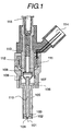
- Fig. 1 is a cross sectional view showing the structure of an embodiment of the fuel injection valve relating to the present invention.
- the fuel injection valve shown in Fig. 1 is an electromagnetic fuel injection valve of a closed type at normal time and when no current is supplied to a coil 112, a valve body (a plunger rod) 110 and a valve seat 104 are adhered closely to each other.
- Fuel in a state that pressure is given by a fuel pump not drawn, is fed from a fuel feed port and the interval from a fuel path 115 to the adhered position of the valve body 110 and the valve seat 104 is filled with fuel.
- a voltage is applied to the coil 112 from a connector 114, magnetic force passing a core 113 and an anchor 108 is generated and the valve body 110 connected by the anchor 108 and a joint pipe 109 is displaced.
- fuel is injected from an injection hole 101.
- the fuel reaches the injection hole 101 through a rotation groove formed in a swirl element 103 and when passing the rotation groove of the swirl element 103, the fuel is given swirling force and is rotated and injected from the injection hole 101.
- An injection valve for rotating and flowing out fuel from the injection hole by the means for generating the swirling force in fuel like this is hereinafter referred to as a swirl type fuel injection valve.
- the means for giving the swirling force to fuel does not need to be a swirl element and a groove-shaped flow path formed in the valve body or a flow path through which fuel passes may be installed so as to rotate the fuel.
- Fig. 2(a) is a cross sectional view of the enlarged neighborhood of the valve seat 104 and the injection hole 101 of the fuel injection valve shown in Fig. 1.
- end faces 204 and 205 have a level difference in the injection hole 101 and spray 203 formed, on the side of the end face 204 on the side of the injection hole 101 which is shorter, becomes spray having strong penetration.
- the section A-A (the cross sectional view) of the spray 203 has a horseshoe shape.
- the horseshoe-shaped spray is in a spray shape having a concentrated part 202 of high-concentration spray and a lean part 206 of low-concentration spray in a part of a hollow conical spray in the spray shape injected from a general swirl type injection valve.
- the cross sectional view shown in Fig. 2(b) is a drawing of spray viewed from the downstream side of the fuel injection valve and a combustion rotational direction 207 is the direction of the arrow.
- the horseshoe shape of spray shown in the cross sectional view in Fig. 2(b) is the spray shape when fuel is injected into air under the atmospheric pressure.
- the shape of spray is affected by the density and pressure of the atmosphere. For example, when fuel is injected into an atmosphere whose pressure is raised and whose concentration is increased, the spray shape shown in the cross sectional view in Fig. 2(b) is changed to a shape as shown in Fig. 3(a).
- the spray concentrated part 202 since spray is concentrated, is hardly affected by the air flow, so that the shape is comparatively kept.
- the spray concentrated part 202 is also affected by the air flow and is slightly rotated in a rotational direction 303 of the concentrated part shown by the arrow.
- the rotational direction 303 is the same as the rotational direction 207 of fuel flow.
- the degree of rotation varies with the density of ambient gas , so that when the pressure of ambient gas is changed, the rotation amount indicating the degree of rotation is also changed, thus as the pressure and density are increased, the rotation amount is increased.
- the spray concentrated part 202 is directed toward the ignition plug, the air-fuel ratio around the ignition plug can be stably increased, so that the ignitablity can be improved, and an miss fire can be prevented, and the combustion stability can be improved.
- stratified combustion is a method that mixed gas in the combustion chamber has a concentrated part and a rarefied part, and a part of a high combustible air-fuel ratio is formed in the neighborhood of the ignition plug, thus as a whole, combustion using mixed gas of a high air-fuel ratio (that is, rarefied fuel) is executed.
- the fuel injection valve is attached to the internal combustion engine. Namely, for the direction of a spray concentrated part 202 generated when the spray concentrated part 302 generated under a high pressure is injected into ambient gas under the atmospheric pressure, in the rotational direction 207 of the fuel flow, the fuel injection valve is mounted in the direction 208 of the ignition plug in the rotational direction 303 of the spray concentrated part.
- the fuel injection valve is attached to the internal combustion engine so that the spray concentrated part 202 generated when fuel is injected into the ambient gas under the atmospheric pressure is directed toward the position of an ignition plug 403, while the fuel injection valve itself, when fuel is injected under the condition that the pressure of ambient gas injected in the compression stroke is high, is mounted at the position when it is rotated in the opposite direction of the combustion rotational direction.
- Fig. 2(c) is a plan view of the injection hole 101 of the fuel injection valve shown in Fig. 1 which is viewed from underneath.
- the end face 205 which is the top of the step formed in parallel with the plane perpendicular to the central axis of the injection hole and the end face 204 which is the bottom of the step are formed and the end face 205 is installed on the downstream side of the end face 204 in the fuel flow direction.
- Wall faces 209 and 210 are almost parallel with the central axis of the injection hole and there is a level difference face installed so as to join the end faces 205 and 204 in the direction of the central axis of the injection hole.
- a rotation restriction wall face is installed in the rotational direction of the fuel flow so as to be almost parallel with the central axis of the injection hole.
- the rotation restriction wall face is installed on the circular arc of the almost concentric circle with the inner wall of the injection hole so as to restrict the motion of fuel in the radial direction. Fuel flowing while rotating flows out while rotating along the rotation restriction wall face.
- the rotation restriction wall face is joined to the wall faces 209 and 210 outward restriction wall face ends 211 and 212 in the radial direction of the injection hole and acts as a movement restriction wall face for restricting the motion of injected fuel in the moving direction.
- the restriction wall face is installed in a part of the range of the injection hole in the peripheral direction and a function as a restriction wall face along the rotation of fuel is provided between the restriction wall face ends 211 and 212.
- the restriction wall face end 211 when the position thereof is viewed as a reference, is arranged at the position when the end face 205 is arranged on the downstream side (the end face 204 is arranged on the upstream side in the rotational direction 207) of the rotational direction 207.
- the restriction wall face end 212 is arranged at the position when the end face 205 is arranged on the upstream side (the end face 205 is arranged on the downstream side in the rotational direction 207) of the rotational direction 207.
- the restriction wall face in the front view, is installed so as to almost coincide with an inner wall 213 of the injection hole. Therefore, the restriction wall face can be regarded as a part of the injection inner wall.
- the restriction wall face end 211 is an upstream side restriction wall face end and the restriction wall face end 212 is a downstream side restriction wall face end.
- the shape of spray injected from the fuel injection valve in which the opening of the injection hole 101 is formed like this, as shown in Fig. 2(b), so that spray in a biased hollow conical shape is obtained and the hollow conical spray 201 composed of the spray concentrated part 202 of the part of high spray concentration and the part of rarefied spray concentration is also generated, can be adjusted by the position relationship of the end faces 209 and 210 formed outward the injection hole 101 from the restriction wall face ends 211 and 212.
- Fig. 3(b) is a diagram showing the relationship between the rotation amount of the spray concentrated part, which is the part of high spray concentration, to the swirl force and the combustion chamber pressure.
- the rotation amount indicates the angle in the rotational direction 303 and swirl force S 1 larger than reference swirl force S 0 and swirl force S 2 smaller than it have a relationship as shown in Fig. 3(c).
- the rotation amount of the spray concentrated part which is the part of high spray concentration is increased. Therefore, according to the rotation amount, the rotation position of the fuel injection valve can be set.
- Fig. 4(a) is a cross sectional view showing a structure example of the fuel injection valve attached to an internal combustion engine of an combustion chamber direct injection type
- Fig. 4(b) is a cross sectional view of the section D-D shown in Fig. 4(a).
- a fuel injection valve 401 is mounted on the side of a suction valve 404 so that the spray concentrated part 402 moves toward the ignition plug 403.
- the cross sectional view (b) of D-D the fuel spray state is drawn in the cross sectional view of the internal combustion engine.
- the cross sectional view (b) of D-D is a drawing viewed from the side of the fuel injection valve and the viewing direction thereof is opposite to that of the cross sectional view of spray shown in Fig. 2(b).
- a spray concentrated part 402' is mounted by adjusting the mounting position of the fuel injection hole 401 so that it is arranged at the position when it rotates in the opposite direction of a combustion rotational direction 406. Namely, when fuel is injected into an ambience under a high pressure, the fuel injection valve is mounted at the position in the opposite direction of the combustion rotational direction 406 toward the ignition plug 403 from the position 208 where a spray concentrated part under the atmospheric pressure is generated.
- the spray concentrated part 402' rotates in the rotational direction 406 and is correctly directed toward the electrode of the ignition plug 403.
- the concentration of fuel around the electrode is apt to increase, and the ignitability can be improved, and the combustion stability can be enhanced.
- the combustion chamber pressure of the internal combustion engine changes depending on the operation conditions such as the engine speed, load, and EGR (exhaust gas recirculation) amount of the engine and the fuel injection time, so that the aforementioned rotation amount of the spray concentrated part is also changed depending on the operation conditions of the internal combustion engine. Therefore, the rotation amount when the fuel injection valve is mounted is adjusted to the rotation amount at which the combustion stability is to be most improved among the operation conditions.
- EGR exhaust gas recirculation
- a fuel concentrated part rotated under the conditions of low engine speed and a small fuel injection amount such as idling toward the ignition plug When the engine speed is low, compared with a case of fast engine speed, the timing of fuel injection approaches the top dead center, so that the combustion chamber pressure is easily increased. Particularly, when the EGR is performed, the combustion chamber pressure is increased. Further, the load is small, thus the fuel injection amount is reduced, and the fuel amount around the ignition plug is reduced, so that it is a condition under which the combustion stability can be hardly ensured.
- the fuel injection valve is mounted. Namely, under the idling conditions (the combustion chamber pressure and density of ambient gas at the time of fuel injection), when the mounting rotation amount of the fuel injection valve is adjusted so that the spray concentrated part is directed toward the ignition plug, the combustion stability during idling can be improved.
- the rotation amount of the spray concentrated part under the idling conditions (for example, 550 rpm, an air-fuel ratio of 40, an EGR rate of 60%, 40° BTDC at the time of fuel injection) is set by shifting by 5 to 15° in the opposite direction of the combustion rotational direction for a case that fuel is injected into ambient gas under the atmospheric pressure. Therefore, the fuel injection valve, compared with the case that it is mounted so that the spray concentrated part when fuel is injected into an ambient gas under the atmospheric pressure is directed toward the ignition plug, is rotated and mounted in the opposite direction of the combustion rotational direction shifted by 5 to 15°.
- the combustion chamber pressure is increased more than it, so that the mounting rotation amount of the fuel injection valve is also increased.
- a mounting rotation amount of the fuel injection valve smaller than it may be used.
- the engine speed is higher than that at the time of idling, so that the fuel injection time viewed by the crank angle is earlier than that at the time of idling, thus fuel is injected when the combustion chamber pressure is low, and the rotation amount of the spray concentrated part is also used in a small state.
- the combustion stability under the use conditions can be improved.
- the performance (for example, fuel consumption, output, exhaust) of the internal combustion engine of an combustion chamber direct injection type can be improved. It is known that the performance of the internal combustion engine varies with the fuel injection time and ignition time. However, when the combustion stability is enhanced, the fuel injection time and ignition time realizing stable combustion can be spread in the range. Therefore, an injection time and an ignition time realizing lower fuel consumption, higher output, and less exhaust can be selected. By doing this, the performance of the internal combustion engine of a direct injection type can be improved.
- the mounting method of the fuel injection valve of the present invention when operating the internal combustion engine of a combustion chamber direct injection type by homogeneous combustion, an effect of reducing smoldering or wetting of the ignition plug can be obtained.
- the ambient pressure when fuel is injected is low.
- the penetration of the spray concentrated part 402' is strong and during the period before ignition, spray reaches far away from the injection point.
- the spray concentrated part 402' is mounted so as to avoid the ignition plug 403, so that the fuel amount adhered to the ignition plug 403 can be suppressed and an occurrence of smoldering of the ignition plug can be suppressed.
- the effects of the present invention are not limited to a case that as shown in Fig. 2, the fuel injection valve formed so that the end faces 204 and 205 have a level difference in the injection hole 101 is used. If a fuel injection valve generates a high concentration and a low concentration of injected spray, the effects of the present invention can be obtained.
- Fig. 5 is a cross sectional view of a fuel injection valve in which the opening of an injection hole 503 is formed by a slope.
- the fuel injection valve shown in Fig. 5 is a rotation type fuel injection valve through which fuel flows out while rotating.
- the fuel injection valve shown in Fig. 5 is a fuel injection valve in which the opening of the injection hole 503 is formed by a slope and the spray shape is as shown by the section B-B (the cross sectional view) shown in Fig. 5.
- the opening of the injection hole 503 is formed by a slope and in the cross section of injected spray, hollow conical spray 501 and a crescent spray concentrated part 502 having a higher spray concentration than it are formed. Even when the fuel injection valve as shown in Fig. 5 is used in the internal combustion engine of an combustion chamber direct injection type, to improve the combustion stability, the spray concentrated part 502 is desirably directed toward the ignition plug.
- Fig. 6 is a cross sectional view of the fuel injection valve showing an example when an injection hole 601 is installed with a slope to the axis of the fuel injection valve.
- the fuel injection valve shown in Fig. 6 is a rotation type fuel injection valve through which fuel flows out while rotating.
- the concentrated part 602 is drawn so as to be formed in the inclination direction of the injection hole 601, though this position is adjustable.
- the position of the spray concentrated part 602, by the swirl force of fuel, the length of the injection hole 601, and the position relationship between the injection hole 601 and the swirl chamber 605, can change the position in the hollow conical spray 603.
- the spray concentrated part 602 is desirably directed toward the ignition plug.
- the spray concentrated part can be made comparatively wide, so that to a phenomenon that the spray concentrated part is rotated in a pressurized atmosphere, the spray concentrated part can be made insensitive.
- a phenomenon that the spray concentrated part is rotated in the rotational direction in a pressurized atmosphere occurs, so that when the spray concentrated part under the ambient pressure is directed toward the ignition plug, the combustion stability is not always best.
- the combustion stability can be improved.
- Fig. 7 is composed of a top view (a) and a front view (b) showing the mounting positions of a fuel injection valve to an internal combustion engine showing respectively the rotation positions on the mounting portion of the fuel injection valve and internal combustion engine.
- a mark 701 indicating the rotation position is installed, and also on the mounting portion of the internal combustion engine, the similar mark is installed, and at the time of mounting, these marks are adjusted to each other, thus precise mounting can be realized.
- the mark 701 when the fuel injection valve is mounted on the internal combustion engine, may be installed so that the fuel injection valve is rotated and mounted in the opposite direction of the combustion rotational direction instead of the direction in which the spray concentrated part in the atmosphere under the atmospheric pressure is directed toward the ignition plug.
- Fig. 8 is a top view showing the mounting state of the means for specifying the rotational direction to the internal combustion engine of the fuel injection valve.
- a pin 803 is installed outside a fuel injection valve 801, outside a fuel injection valve 801, a pin 803 is installed.
- the pin 803 is installed on a resin mold portion 802 formed together with a connector.
- a striking portion 805 of the pin 803 is installed on a mounting portion 804 of the cylinder head of the internal combustion engine on the fuel injection valve, and when mounting the fuel injection valve 801 on the internal combustion engine, it is mounted so that the pin 803 and the pin receiver 805 make contact with each other, thus the fuel injection valve 801 can be mounted in the rotational direction as preset.
- the pin receiver 805 may be installed on the mounting portion of the fuel injection valve on the internal combustion engine not only as a projection but also as a plane or a concavity.
- the mounting rotation amount of the fuel injection valve 801 may be adjusted by the projection length of the pin 803.
- the pin 803 at the manufacturing step of the fuel injection valve, for example, a plurality of long and short pins are prepared and on the basis of the measured value of the position of the concentrated part of spray injected from the fuel injection valve in the rotational direction, may be selectively fit into the hole formed in the resin mold portion 802.
- the pin 803, on the basis of the measured value of the position of the concentrated part of spray injected from the fuel injection valve in the rotational direction may be ground. Further, when the pin 803 is ground and used like this, if the pin 803 is formed integrally with the resin mold portion 802, the number of parts can be reduced and the manufacturing cost can be suppressed.
- the projection length of the pin 803, when the fuel injection valve 801 is mounted on the internal combustion engine, may be installed so that the fuel injection valve is rotated and mounted in the opposite direction of the rotational direction of the fuel flow 807 instead of the direction in which the spray concentrated part in the atmosphere under the atmospheric pressure is directed toward the ignition plug.
- the ignition plug is arranged on the line in a direction 808 of the ignition plug.
- the position of the spray concentrated part in the rotational direction may be varied.
- the position of a spray concentrated part 806 is measured, and the length of the pin 803 is adjusted according to the measured value, thus the spray concentrated part is correctly directed toward the ignition plug, and variations in the combustion stability due to variations in the manufacture can be suppressed.
- Fig. 9 is a top view showing the mounting state of a fuel injection valve on an internal combustion engine showing another example that a pin is installed outside the fuel injection valve.
- Fig. 9 shows an example that a pin 903 is installed on the cylindrical peripheral surface of a fuel injection valve 901.
- the position of the pin 903 on the cylindrical structure of the fuel injection valve 901 is adjusted.
- the position of the pin 903 to be installed is decided, and a hole is bored on the peripheral surface of the fuel injection valve 901, and the pin 903 is fit into it.
- a hollow 905 which is a pin receiver is formed.
- the fuel injection valve When the fuel injection valve is mounted, it is mounted so that the pin 903 is fit into the hollow 905, thus when the fuel injection valve is mounted on the internal combustion engine, the fuel injection valve may be installed so that the fuel injection valve is rotated and mounted in the opposite direction of the rotational direction of the fuel flow 907 instead of the direction in which the spray concentrated part in the atmosphere under the atmospheric pressure is directed toward the ignition plug.
- the ignition plug is arranged on the line in a direction 908 of the ignition plug.
- Fig. 10 is a drawing showing the relationship between the shape of the front end of the nozzle of the fuel injection valve having the positioning pin in the mounting rotational direction shown in Figs. 8 and 9 and spray in an example that for the fuel injection valve, a nozzle having a level difference at its front end as shown in Fig. 2 is used.
- Fig. 10 to show the relationship between the nozzle and spray, the size of the nozzle is drawn exaggeratingly.
- the end face 205 of the nozzle as shown in Fig.
- a direction 1001 in which the spray concentrated part 806 is generated is a tangential direction of the injection hole 101 at the position where the edge of the injection hole 101 and the level different portion 1002 intersect. Therefore, when installing, on a fuel injection valve having a level difference at the front end of the nozzle as shown in Fig. 2, a positioning means in the rotational direction of the fuel injection valve shown in Figs.
- Fig. 11 is a graph showing the situation that when the fuel injection valve as shown in Fig. 2 is attached to the internal combustion engine as shown in Fig. 4, the combustion stability is improved by the present invention.
- the axis of abscissa indicates a mounting angle of the injector in the rotational direction and the rightward direction is the rotational direction of fuel.
- a position 1101 of 0° on the axis of abscissa is the position toward which the fuel concentrated part when the fuel injection valve injects fuel into an atmosphere under the atmospheric pressure is directed.
- the combustion stability indicated by the axis of ordinate indicates the ranges of stable combustion of the injection time and ignition time when the internal combustion engine is operated by shifting respectively the fuel injection time and ignition time and the upper part of the graph indicates that the stable range is wide.
- a line 1103 on the graph indicates the lower limit of combustion stability. As shown in Fig. 11, when the mounting angle of the injector in the rotational angle is shifted, even if the injection time and ignition time are shifted like a point 1104 and a point 1105, stable combustion cannot be realized.
- the combustion stability is optimized, as shown by a line 1102, when the fuel injection valve is rotated and mounted in an about 5° arc in the opposite direction of the rotational direction of fuel.
- the mounting position in the rotational direction is set at the position 0° as indicated by the line 1101
- the tolerance of fuel in the rotational direction of fuel is narrowed.
- the mounting position in the rotational direction is set at the position as indicated by the line 1101
- the tolerance of variations of fuel in the rotational direction is narrowed and depending on variations in the mounting position in the rotational direction, no stable combustion can be obtained.
- the mounting position of the fuel injection valve in the rotational direction is shifted to the position in the opposite direction of the rotational direction as indicated by the line 1102, so that the tolerance of variations can be increased.
- the tolerance of variations can be increased.
Landscapes
- Engineering & Computer Science (AREA)
- Chemical & Material Sciences (AREA)
- Combustion & Propulsion (AREA)
- Mechanical Engineering (AREA)
- General Engineering & Computer Science (AREA)
- Fuel-Injection Apparatus (AREA)
- Combustion Methods Of Internal-Combustion Engines (AREA)
Applications Claiming Priority (2)
| Application Number | Priority Date | Filing Date | Title |
|---|---|---|---|
| JP2003353563 | 2003-10-14 | ||
| JP2003353563A JP4135926B2 (ja) | 2003-10-14 | 2003-10-14 | 内燃機関の燃料噴射弁及び内燃機関 |
Publications (2)
| Publication Number | Publication Date |
|---|---|
| EP1524429A1 true EP1524429A1 (de) | 2005-04-20 |
| EP1524429B1 EP1524429B1 (de) | 2008-05-28 |
Family
ID=34373540
Family Applications (1)
| Application Number | Title | Priority Date | Filing Date |
|---|---|---|---|
| EP04024515A Expired - Lifetime EP1524429B1 (de) | 2003-10-14 | 2004-10-14 | Kraftstoffeinspritzverfahren einer Brennkraftmaschine, Kraftstoffeinspritzsystem und Brennkraftmaschine dafür |
Country Status (4)
| Country | Link |
|---|---|
| US (1) | US7082922B2 (de) |
| EP (1) | EP1524429B1 (de) |
| JP (1) | JP4135926B2 (de) |
| DE (1) | DE602004014084D1 (de) |
Cited By (1)
| Publication number | Priority date | Publication date | Assignee | Title |
|---|---|---|---|---|
| CN107989716A (zh) * | 2018-01-02 | 2018-05-04 | 吉林大学 | 一种进气道内燃气喷射方向可变装置 |
Families Citing this family (3)
| Publication number | Priority date | Publication date | Assignee | Title |
|---|---|---|---|---|
| JP2006214292A (ja) * | 2005-02-01 | 2006-08-17 | Hitachi Ltd | 燃料噴射弁 |
| WO2008038396A1 (en) * | 2006-09-25 | 2008-04-03 | Hitachi, Ltd. | Fuel injection valve |
| US7571708B2 (en) * | 2007-09-10 | 2009-08-11 | Gm Global Technology Operations, Inc. | Spark ignited direct injection targeting for improved combustion |
Citations (4)
| Publication number | Priority date | Publication date | Assignee | Title |
|---|---|---|---|---|
| EP1036933A2 (de) * | 1999-03-17 | 2000-09-20 | Hitachi, Ltd. | Brennstoffeinspritzventil und Brennkraftmaschine |
| DE10007659A1 (de) * | 2000-02-19 | 2001-09-06 | Daimler Chrysler Ag | Otto-Brennkraftmaschine |
| EP1191199A1 (de) * | 1999-06-11 | 2002-03-27 | Hitachi, Ltd. | Direkteingespritzter motor und verfahren zum betreiben des motors |
| EP1219826A2 (de) * | 2000-12-26 | 2002-07-03 | Hitachi, Ltd. | Verfahren zur Herstellung eines Brennstoffeinspritzventils, Brennstoffeinspritzventil, sowie damit ausgerüstete Brennkraftmaschine |
Family Cites Families (4)
| Publication number | Priority date | Publication date | Assignee | Title |
|---|---|---|---|---|
| US4721081A (en) * | 1986-06-03 | 1988-01-26 | Caterpillar Inc. | Flame incubating and propagating apparatus for a fuel combustion system |
| US5058549A (en) * | 1988-02-26 | 1991-10-22 | Toyota Jidosha Kabushiki Kaisha | Fuel swirl generation type fuel injection valve and direct fuel injection type spark ignition internal combustion engine |
| US6227164B1 (en) * | 1998-04-24 | 2001-05-08 | Cooper Automotive Products, Inc. | Insulator shield for spark plug |
| LU90599B1 (en) | 2000-06-14 | 2001-12-17 | Delphi Tech Inc | Fuel injector injection system and method for supplying fuel |
-
2003
- 2003-10-14 JP JP2003353563A patent/JP4135926B2/ja not_active Expired - Fee Related
-
2004
- 2004-10-13 US US10/962,753 patent/US7082922B2/en not_active Expired - Fee Related
- 2004-10-14 DE DE602004014084T patent/DE602004014084D1/de not_active Expired - Lifetime
- 2004-10-14 EP EP04024515A patent/EP1524429B1/de not_active Expired - Lifetime
Patent Citations (4)
| Publication number | Priority date | Publication date | Assignee | Title |
|---|---|---|---|---|
| EP1036933A2 (de) * | 1999-03-17 | 2000-09-20 | Hitachi, Ltd. | Brennstoffeinspritzventil und Brennkraftmaschine |
| EP1191199A1 (de) * | 1999-06-11 | 2002-03-27 | Hitachi, Ltd. | Direkteingespritzter motor und verfahren zum betreiben des motors |
| DE10007659A1 (de) * | 2000-02-19 | 2001-09-06 | Daimler Chrysler Ag | Otto-Brennkraftmaschine |
| EP1219826A2 (de) * | 2000-12-26 | 2002-07-03 | Hitachi, Ltd. | Verfahren zur Herstellung eines Brennstoffeinspritzventils, Brennstoffeinspritzventil, sowie damit ausgerüstete Brennkraftmaschine |
Cited By (2)
| Publication number | Priority date | Publication date | Assignee | Title |
|---|---|---|---|---|
| CN107989716A (zh) * | 2018-01-02 | 2018-05-04 | 吉林大学 | 一种进气道内燃气喷射方向可变装置 |
| CN107989716B (zh) * | 2018-01-02 | 2023-12-15 | 吉林大学 | 一种进气道内燃气喷射方向可变装置 |
Also Published As
| Publication number | Publication date |
|---|---|
| EP1524429B1 (de) | 2008-05-28 |
| US20050109311A1 (en) | 2005-05-26 |
| JP2005120840A (ja) | 2005-05-12 |
| US7082922B2 (en) | 2006-08-01 |
| JP4135926B2 (ja) | 2008-08-20 |
| DE602004014084D1 (de) | 2008-07-10 |
Similar Documents
| Publication | Publication Date | Title |
|---|---|---|
| US6705274B2 (en) | In-cylinder direct injection spark-ignition internal combustion engine | |
| US6092743A (en) | Fuel injection valve | |
| US4899699A (en) | Low pressure injection system for injecting fuel directly into cylinder of gasoline engine | |
| JP4055315B2 (ja) | 燃料噴射弁およびこれを搭載した内燃機関 | |
| JP2003534495A (ja) | 燃料噴射システム | |
| JP2002227650A (ja) | ナッペ角が小さい直噴エンジンおよびこのようなエンジンの使用を可能にする方法 | |
| JP2609929B2 (ja) | 燃料噴射弁 | |
| EP1069291A2 (de) | Direkteinspritzbrennkraftmaschine mit Fremdzündung | |
| US20080208437A1 (en) | Fuel-Injector For Internal-Combustion Engine, Methods of Controlling Fuel-Injector, Electronic Control Unit for Fuel-Injector, and Fuel Injection System for Direct Fuel-Injection Engine | |
| US6935578B1 (en) | Fuel injection valve | |
| EP1524429B1 (de) | Kraftstoffeinspritzverfahren einer Brennkraftmaschine, Kraftstoffeinspritzsystem und Brennkraftmaschine dafür | |
| JPH11343947A (ja) | 内燃機関用燃料噴射弁 | |
| JP7420457B2 (ja) | ポート噴射式内燃機関 | |
| JP3044876B2 (ja) | 内燃機関用電子制御燃料噴射装置 | |
| JP3774822B2 (ja) | 可変スワール型燃料直噴インジェクタ | |
| JP3692745B2 (ja) | 内燃機関の燃料噴射制御装置 | |
| JP2005171866A (ja) | 燃料噴射制御装置 | |
| JP3804315B2 (ja) | 筒内直接噴射式内燃機関の燃料噴射弁 | |
| KR200198868Y1 (ko) | 디젤 엔진의 평면형 분사 노즐 | |
| JP2000240536A (ja) | 筒内燃料噴射装置 |
Legal Events
| Date | Code | Title | Description |
|---|---|---|---|
| PUAI | Public reference made under article 153(3) epc to a published international application that has entered the european phase |
Free format text: ORIGINAL CODE: 0009012 |
|
| AK | Designated contracting states |
Kind code of ref document: A1 Designated state(s): AT BE BG CH CY CZ DE DK EE ES FI FR GB GR HU IE IT LI LU MC NL PL PT RO SE SI SK TR |
|
| AX | Request for extension of the european patent |
Extension state: AL HR LT LV MK |
|
| 17P | Request for examination filed |
Effective date: 20050811 |
|
| AKX | Designation fees paid |
Designated state(s): DE FR |
|
| 17Q | First examination report despatched |
Effective date: 20060620 |
|
| GRAP | Despatch of communication of intention to grant a patent |
Free format text: ORIGINAL CODE: EPIDOSNIGR1 |
|
| GRAS | Grant fee paid |
Free format text: ORIGINAL CODE: EPIDOSNIGR3 |
|
| GRAA | (expected) grant |
Free format text: ORIGINAL CODE: 0009210 |
|
| AK | Designated contracting states |
Kind code of ref document: B1 Designated state(s): DE FR |
|
| REF | Corresponds to: |
Ref document number: 602004014084 Country of ref document: DE Date of ref document: 20080710 Kind code of ref document: P |
|
| PLBE | No opposition filed within time limit |
Free format text: ORIGINAL CODE: 0009261 |
|
| STAA | Information on the status of an ep patent application or granted ep patent |
Free format text: STATUS: NO OPPOSITION FILED WITHIN TIME LIMIT |
|
| 26N | No opposition filed |
Effective date: 20090303 |
|
| PG25 | Lapsed in a contracting state [announced via postgrant information from national office to epo] |
Ref country code: FR Free format text: LAPSE BECAUSE OF NON-PAYMENT OF DUE FEES Effective date: 20101102 |
|
| REG | Reference to a national code |
Ref country code: FR Ref legal event code: ST Effective date: 20110630 |
|
| PGFP | Annual fee paid to national office [announced via postgrant information from national office to epo] |
Ref country code: FR Payment date: 20091006 Year of fee payment: 6 |
|
| PGFP | Annual fee paid to national office [announced via postgrant information from national office to epo] |
Ref country code: DE Payment date: 20121010 Year of fee payment: 9 |
|
| REG | Reference to a national code |
Ref country code: DE Ref legal event code: R119 Ref document number: 602004014084 Country of ref document: DE Effective date: 20140501 |
|
| PG25 | Lapsed in a contracting state [announced via postgrant information from national office to epo] |
Ref country code: DE Free format text: LAPSE BECAUSE OF NON-PAYMENT OF DUE FEES Effective date: 20140501 |