EP1524140A1 - Vehicle pressure relief valve - Google Patents
Vehicle pressure relief valve Download PDFInfo
- Publication number
- EP1524140A1 EP1524140A1 EP20040024317 EP04024317A EP1524140A1 EP 1524140 A1 EP1524140 A1 EP 1524140A1 EP 20040024317 EP20040024317 EP 20040024317 EP 04024317 A EP04024317 A EP 04024317A EP 1524140 A1 EP1524140 A1 EP 1524140A1
- Authority
- EP
- European Patent Office
- Prior art keywords
- base
- flap
- relief valve
- pressure relief
- peripheral portion
- Prior art date
- Legal status (The legal status is an assumption and is not a legal conclusion. Google has not performed a legal analysis and makes no representation as to the accuracy of the status listed.)
- Withdrawn
Links
Images


Classifications
-
- B—PERFORMING OPERATIONS; TRANSPORTING
- B60—VEHICLES IN GENERAL
- B60H—ARRANGEMENTS OF HEATING, COOLING, VENTILATING OR OTHER AIR-TREATING DEVICES SPECIALLY ADAPTED FOR PASSENGER OR GOODS SPACES OF VEHICLES
- B60H1/00—Heating, cooling or ventilating devices
- B60H1/24—Ventilating devices where the heating or cooling is irrelevant
- B60H1/248—Air-extractors, air-evacuation from the vehicle interior
- B60H1/249—Air-extractors, air-evacuation from the vehicle interior using one-way valves
-
- F—MECHANICAL ENGINEERING; LIGHTING; HEATING; WEAPONS; BLASTING
- F16—ENGINEERING ELEMENTS AND UNITS; GENERAL MEASURES FOR PRODUCING AND MAINTAINING EFFECTIVE FUNCTIONING OF MACHINES OR INSTALLATIONS; THERMAL INSULATION IN GENERAL
- F16K—VALVES; TAPS; COCKS; ACTUATING-FLOATS; DEVICES FOR VENTING OR AERATING
- F16K15/00—Check valves
- F16K15/14—Check valves with flexible valve members
- F16K15/144—Check valves with flexible valve members the closure elements being fixed along all or a part of their periphery
- F16K15/145—Check valves with flexible valve members the closure elements being fixed along all or a part of their periphery the closure elements being shaped as a solids of revolution, e.g. cylindrical or conical
-
- F—MECHANICAL ENGINEERING; LIGHTING; HEATING; WEAPONS; BLASTING
- F16—ENGINEERING ELEMENTS AND UNITS; GENERAL MEASURES FOR PRODUCING AND MAINTAINING EFFECTIVE FUNCTIONING OF MACHINES OR INSTALLATIONS; THERMAL INSULATION IN GENERAL
- F16K—VALVES; TAPS; COCKS; ACTUATING-FLOATS; DEVICES FOR VENTING OR AERATING
- F16K15/00—Check valves
- F16K15/14—Check valves with flexible valve members
- F16K15/144—Check valves with flexible valve members the closure elements being fixed along all or a part of their periphery
- F16K15/147—Check valves with flexible valve members the closure elements being fixed along all or a part of their periphery the closure elements having specially formed slits or being of an elongated easily collapsible form
-
- F—MECHANICAL ENGINEERING; LIGHTING; HEATING; WEAPONS; BLASTING
- F16—ENGINEERING ELEMENTS AND UNITS; GENERAL MEASURES FOR PRODUCING AND MAINTAINING EFFECTIVE FUNCTIONING OF MACHINES OR INSTALLATIONS; THERMAL INSULATION IN GENERAL
- F16K—VALVES; TAPS; COCKS; ACTUATING-FLOATS; DEVICES FOR VENTING OR AERATING
- F16K15/00—Check valves
- F16K15/14—Check valves with flexible valve members
- F16K15/144—Check valves with flexible valve members the closure elements being fixed along all or a part of their periphery
-
- Y—GENERAL TAGGING OF NEW TECHNOLOGICAL DEVELOPMENTS; GENERAL TAGGING OF CROSS-SECTIONAL TECHNOLOGIES SPANNING OVER SEVERAL SECTIONS OF THE IPC; TECHNICAL SUBJECTS COVERED BY FORMER USPC CROSS-REFERENCE ART COLLECTIONS [XRACs] AND DIGESTS
- Y10—TECHNICAL SUBJECTS COVERED BY FORMER USPC
- Y10T—TECHNICAL SUBJECTS COVERED BY FORMER US CLASSIFICATION
- Y10T137/00—Fluid handling
- Y10T137/0318—Processes
- Y10T137/0402—Cleaning, repairing, or assembling
- Y10T137/0491—Valve or valve element assembling, disassembling, or replacing
-
- Y—GENERAL TAGGING OF NEW TECHNOLOGICAL DEVELOPMENTS; GENERAL TAGGING OF CROSS-SECTIONAL TECHNOLOGIES SPANNING OVER SEVERAL SECTIONS OF THE IPC; TECHNICAL SUBJECTS COVERED BY FORMER USPC CROSS-REFERENCE ART COLLECTIONS [XRACs] AND DIGESTS
- Y10—TECHNICAL SUBJECTS COVERED BY FORMER USPC
- Y10T—TECHNICAL SUBJECTS COVERED BY FORMER US CLASSIFICATION
- Y10T137/00—Fluid handling
- Y10T137/7722—Line condition change responsive valves
- Y10T137/7837—Direct response valves [i.e., check valve type]
- Y10T137/7838—Plural
- Y10T137/7839—Dividing and recombining in a single flow path
- Y10T137/784—Integral resilient member forms plural valves
-
- Y—GENERAL TAGGING OF NEW TECHNOLOGICAL DEVELOPMENTS; GENERAL TAGGING OF CROSS-SECTIONAL TECHNOLOGIES SPANNING OVER SEVERAL SECTIONS OF THE IPC; TECHNICAL SUBJECTS COVERED BY FORMER USPC CROSS-REFERENCE ART COLLECTIONS [XRACs] AND DIGESTS
- Y10—TECHNICAL SUBJECTS COVERED BY FORMER USPC
- Y10T—TECHNICAL SUBJECTS COVERED BY FORMER US CLASSIFICATION
- Y10T137/00—Fluid handling
- Y10T137/7722—Line condition change responsive valves
- Y10T137/7837—Direct response valves [i.e., check valve type]
- Y10T137/7879—Resilient material valve
- Y10T137/7888—With valve member flexing about securement
Definitions
- the present invention relates to a pressure relief valve and a method of manufacturing the same. More particularly, the present invention relates to a pressure relief valve for relieving pressure from a passenger compartment of a vehicle and the method of manufacturing the pressure relief valve.
- Pressure relief valves for relieving pressure from a passenger compartment of a vehicle are known.
- Conventional pressure relief valves include a gate that opens when a differential air pressure between the passenger compartment of the vehicle and atmosphere reaches a predetermined level. For example, when a vehicle door is slammed closed, the air pressure within the passenger compartment is likely to increase suddenly.
- the gate of the pressure relief valve is actuated into an open position to relieve the pressure within the passenger compartment.
- the conventional pressure relief valve is a one-way valve that only allows airflow from the passenger compartment to atmosphere and prevents airflow from atmosphere into the passenger compartment.
- the present invention relates to a pressure relief valve for relieving air pressure from a passenger compartment of a vehicle.
- the pressure relief valve comprises a base having a peripheral portion. A central opening extends through the peripheral portion.
- the pressure relief valve also comprises a plurality of flaps for closing the central opening of the base. Each flap has an outer end connected with the peripheral portion of the base and an inner end that is movable relative to the peripheral portion and the other flaps for enabling airflow through the central opening.
- Each flap has opposite surfaces against which air pressure acts. Differential air pressure acts on the opposite surfaces causing the flap to move to enable airflow through the central opening.
- the present invention also relates to a method of forming a pressure relief valve for relieving air pressure from a passenger compartment of a vehicle.
- a base having a peripheral portion and a central opening that extends through the peripheral portion is provided.
- the central opening of the base is closed with a plurality of flaps.
- An outer end of each flap is connected with the peripheral portion of the base. Airflow through the central opening is enabled by causing an inner end of each flap to move relative to the peripheral portion and the other flaps due to differential air pressure acting on opposite surfaces of the flap.
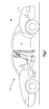
- Fig. 1 is a side view of a vehicle 10 including a pressure relief valve 12 constructed in accordance with the present invention.
- the pressure relief valve 12 separates the passenger compartment 14 of the vehicle 10 from atmosphere 16 and is operable to relieve pressure from the passenger compartment of the vehicle.
- the pressure relief valve 12 is located in the trunk of the vehicle 10.
- the pressure relief valve 12 may be located at other location on the vehicle 10.
- Fig. 2 illustrates a perspective view of an exemplary embodiment of a pressure relief valve 12 constructed in accordance with the present invention.
- An exploded perspective view of the pressure relief valve 12 of Fig. 2 is shown in Fig. 5.
- the pressure relief valve 12 includes a base 18, a flexible closure member 20, and a rim 22.
- the base 18 includes a peripheral portion 30 and a support portion 32.
- the peripheral portion 30 of the base 18 illustrated in Fig. 5 is annular.
- the peripheral portion 30 of the base 18 may be a shape other than annular.
- the peripheral portion 30 may be elliptical or rectangular.
- the peripheral portion 30 includes radial inner and outer surfaces 34 and 36, respectively, and upper and lower surfaces 38 and 40, respectively.
- the surfaces 34, 36, 38, and 40 of the peripheral portion 30 collectively define a rectangular cross-section of the peripheral portion 30.
- the radial outer surface 36 of the peripheral portion 30 defines a diameter of the base 18 and is centered on axis A, shown in Fig. 5.
- the radial inner surface 34 of the peripheral portion 30 extends parallel to and is coaxial with the radial outer surface 36.
- the radial inner surface 34 defines a central opening 42 that extends through the peripheral portion 30 of the base 18.
- the central opening 42 of the base 18 illustrated in Fig. 4 has a diameter of approximately eighty-five percent the diameter of the base.
- the upper surface 38 of the peripheral portion 30 connects the radial inner and outer surfaces 34 and 36 and extends radially relative to axis A.
- two bosses 44 extend outwardly of the upper surface 38 of the peripheral portion 30 of the base 18.
- the two bosses 44 illustrated in Fig. 5 align with one another on opposite sides of axis A.
- Each boss 44 is centrally located on the upper surface 38 of the peripheral portion 30 between the radial inner and outer surfaces 34 and 36.
- the lower surface 40 of the peripheral portion 30 also connects the radial inner and outer surfaces 34 and 36.
- the lower surface 40 extends parallel to the upper surface 38 and radially relative to axis A.
- the support portion 32 of the base 18 includes a central portion 48 and a plurality of radially extending branches 50.
- the support portion 32 for the base 18 illustrated in Fig. 5 includes four radially extending branches 50.
- the central portion 48 is located at the center of the central opening 42.
- the four radially extending branches connect the central portion 48 of the support portion 32 to the peripheral portion 30.
- Each radially extending branch 50 of the support portion of the base includes an upper surface 52 and a lower surface (not shown) and first and second side surfaces 54 and 56, respectively.
- the upper surface 52 of each branch 50 aligns with and extends parallel to the upper surface 38 of the peripheral portion 30 of the base 18.
- the lower surface of each branch 50 aligns with and extends parallel to the lower surface 40 of the peripheral portion 30 of the base 18.
- the first and second side surfaces 54 and 56 extend parallel to one another and have radially outermost ends which join or mate with the radially inner surface 34 of the peripheral portion 30 of the base 18.
- Each branch 50 of the support portion 32 has a rectangular cross-section.
- the branches 50 of the support portion 32 of the base 18 divide the central opening 42 into a plurality of flow openings 58.
- the number of flow openings 58 is equal to the number of branches 50.
- the four branches 50 of the support portion 32 of Fig. 5 divide the central opening 42 into four flow openings 58.
- Three surfaces define each flow opening 58 in the base 18. The three surfaces include a portion of the radial inner surface 34 of the peripheral portion 30, a first side surface 54 of one branch 50, and a second side surface 56 of an adjacent branch 50.
- the four flow openings 58 in the base 18 are sectors of the central opening 42 that extends through the peripheral portion 30 of the base 18.
- the flexible closure member 20 of the pressure relief valve 12 is circular and includes opposite upper and lower surfaces 64 and 66, respectively, (Fig. 4). A center of the flexible closure member 20 is located on axis A.
- arcuate slots 68 extend through the flexible closure member 20 illustrated in Fig. 5.
- the four arcuate slots 68 are spaced equidistance from axis A and are positioned in a spaced array about axis A.
- a distance between arcuate slots 68 located on opposite sides of axis A is approximately eighty-five percent of the diameter of the flexible closure member 20.
- a slit 70 extends from the middle of each arcuate slot 68 to the center of the flexible closure member 20.
- the flexible closure member 20 of Fig. 5 includes four slits 70.
- the four slits 70 meet with one another at axis A.
- a narrow portion 72 (Fig. 5) of the flexible closure member 20 separates adjacent arcuate slots 68 from one another.
- the flexible closure member 20 of Fig. 5 includes four narrow portions 72.
- the flexible closure member 20 includes a plurality of flaps 74.
- the flexible closure member 20 shown in Figs. 2, 3, and 5 includes four flaps 74.
- Each flap 74 forms a sector of the flexible closure member 20 and includes upper and lower surfaces 76 and 78, respectively (Fig. 4).
- Each flap 74 has an inner end 80 (Fig. 5) and an outer end 82 (Fig. 5).
- the inner end 80 of each flap 74 is defined between adjacent slits 70 in the flexible closure member 20.
- the inner end 80 narrows as it extends away from the outer end 82 and toward axis A.
- the inner end 80 of each flap 74 is defined between first and second side portions 84 and 86, respectively, shown on an exemplary flap 74 in Fig. 5.
- each flap 74 is interconnected to the outer end 82 of each adjacent flap 74 so that the outer ends of the plurality of flaps, collectively, form an undivided outer periphery 90 of the flexible closure member 20.
- One of the four narrow portions 72 is associated with each flap 74 and connects the inner end 80 of the flap 74 to the outer end 82 of the flap.
- the narrow portion 72 forms a hinge for enabling the inner end 80 of the flap 74 to move relative to the outer end 82 of the flap.
- the flexible closure member 20 also includes two alignment holes 92.
- the alignment holes 92 are located in the outer periphery 90 of the flexible closure member 20.
- the alignment holes 92 of in the flexible closure member 20 illustrated in Fig. 5 align with one another on opposite sides of axis A and are aligned with two of the slits 70 in the flexible closure member.
- Each of the alignment holes 92 in the flexible closure member 20 is located at a distance from axis A to receive an associated boss 44 of the base 18.
- the rim 22 of the pressure relief valve 12 has an annular main body portion 98 (Fig. 4) that is centered on axis A.
- the main body portion 98 includes an upper surface 100, a lower surface 102, and an annular inner surface 104.
- a diameter of the annular inner surface 104 is less than the diameter of the radial outer surface 36 of the peripheral portion 30 of the base 18.
- the diameter of the annular inner surface 104 is greater than the diameter between radially outermost portions of the arcuate slots 68 of the flexible closure member 20.
- An annular pocket 106 extends into the annular inner surface 104 of the main body portion 98 and the rim 22.
- the annular pocket 106 is defined between a lower surface 108 and an upper surface 110.
- An annular inner surface 112 defines a bottom of the annular pocket 106.
- Interior and exterior locking members 116 and 118 extend from the main body portion 98 of the rim 22.
- the interior locking member 116 is annular and includes a spacer portion 120 and a hooked portion 122.
- the spacer portion 120 extends downwardly, as viewed in Fig. 4, and slightly radially outwardly from the main body portion 98 of the rim 22.
- the hooked portion 122 of the interior locking member 116 is formed on an end of the spacer portion 120 opposite the main body portion 98 of the rim 22.
- the hook portion 122 extends radially outwardly from the spacer portion 120 and includes a surface 124 for engaging and sealing against an interior surface 126 of a panel 128 (shown by dashed lines in Fig. 4) of the vehicle 10.
- the exterior locking member 118 of the rim is an annular tapered member that extends downwardly, as viewed in Fig. 4, and radially outwardly of the main body portion 98 of the rim 22.
- the exterior locking member 118 includes upper and lower surfaces 130 and 132, respectively.
- the upper surface 130 of the exterior locking member 118 extends downwardly and radially outwardly from the upper surface 100 of the main body portion 98 of the rim 22.
- the lower surface 132 of the exterior locking member 118 terminates near a midpoint of the main body portion 98.
- the exterior locking member 118 narrows as it extends downwardly and radially outwardly from the main body portion 98 of the rim 22.
- the exterior locking member 118 is flexible and is designed to engage and seal against an exterior surface 134 of a panel 128 (shown by dashed lines in Fig. 4) of the vehicle 10.
- the pressure relief valve 12 of the present invention is manufactured in a two-shot molding process. Prior to the molding process, the flexible closure member 20 is manufactured.
- the flexible closure member 20 may be made from a Mylar film, polyester, or a polycarbonate-based material.
- the flexible closure member 20 is formed from a single piece of sheet material having a thickness in the range of 3-7 thousandths of an inch.
- the flexible closure member 20 may be stamped or thermoformed from the single piece of sheet material.
- the two-shot molding process may be performed in a single two-shot injection molding machine or, alternatively, may be performed in two separate, one-shot injection molding machines.
- the first shot of the injection molding process forms the base 18 of the pressure relief valve 12.
- the base 18 is formed as a monolithic structure that is free from any connecting devices or fasteners.
- the base 18 is formed from a homogenous material, preferably a polypropylene or thermoplastic and has a uniform density throughout.
- the flexible closure member 20 is placed on the base 18.
- the flexible closure member 20 is placed over the base 18 so that the alignment holes 92 in the flexible closure member 20 receive the bosses 44 on the upper surface 38 of the peripheral portion 30 of the base 18.
- the outer periphery 90 of the flexible closure member 20 overlies the upper surface 38 of the peripheral portion 30 of the base 18.
- each flap 74 of the flexible closure member 20 covers or closes an associated flow opening 58 in the base 18 and the slits 70 that separate adjacent flaps 74 of the flexible closure member 20 are positioned on an upper surface 38 of an associated branch 50 of the support portion 32 of the base 18, as is shown in Figs.
- the second shot of the injection molding process forms the rim 22 of the pressure relief valve 12.
- the rim 22 is also formed as a monolithic structure that is free from any connecting devices or fasteners.
- the rim 22 is formed from a homogenous material, preferably a thermoplastic elastomer, and has a uniform density throughout.
- An exemplary thermoplastic elastomer would be a TPV (thermoplastic vulcanizate) such as SANTOPRENE.
- the material used to form the rim 22 must have a melting point that is lower than the melting points of the materials of the base 18 and the flexible closure member 20.
- the rim 22 is molded directly onto the peripheral portion 30 of the base 18 and outer periphery 90 of the flexible closure member 20.
- the rim 22 fixedly secures the outer periphery 90 of the flexible closure member 20, i.e., the outer ends 82 of the flaps 74, relative to the peripheral portion 30 of the base 18.
- the molded rim 22 chemically bonds to the peripheral portion 30 of the base 18.
- a mechanical bond may be formed between the rim 22 and the peripheral portion 30 of the base 18 using known methods.
- the rim 22 terminates at the annular inner surface 104 in a position radially outward of the arcuate slots 68 of the flexible closure member 20.
- the manufacture of the pressure relief valve 12 of the present invention is complete after the rim 22 is formed.
- the pressure relief valve 12 of the present invention acts as a check valve or one-way valve.
- the pressure relief valve 12 enables airflow from the passenger compartment 14 of the vehicle 10 to atmosphere 16, but prevents airflow from atmosphere 16 into the passenger compartment 14 of the vehicle 10.
- the pressure relief valve 12 of the present invention helps to prevent atmospheric noise, dust, and carbon monoxide from entering the passenger compartment 14 of the vehicle 10.
- the pressure relief valve 12 of the present invention is operable in response to differential air pressure between the passenger compartment 14 of the vehicle 10 and atmosphere 16.
- Fig. 4 illustrates the location of the passenger compartment 14 and atmosphere 16 relative to the pressure relief valve 12 when mounted to a panel 128 of the vehicle 10.
- Fig. 4 also illustrates the pressure relief valve 12 in a closed condition.
- the flaps 74 of the flexible closure member 20 have a tendency to remain flat. Thus, when air pressure within the passenger compartment 14 of the vehicle 10 and atmospheric pressure 16 are equal, the pressure relief valve 12 will remain in a closed condition.
- the tendency of the flaps 74 to remain flat causes the flaps 74 to move back into the closed condition.
- the tendency of the flaps 74 to remain flat biases the flaps 74 into the closed condition.
- the pressure relief valve 12 operates independent of gravity and may be mounted on the vehicle 10 in any orientation.
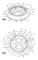
- Fig. 6 is a plan view of a pressure relief valve 12' constructed in accordance with a second embodiment of the present invention. Structure of the pressure relief valve 12' of Fig. 6 that are similar to or perform the same function as structure of the pressure relief valve 12 illustrated in Figs. 2-5 are referred to using the same reference numbers.
- the pressure relief valve 12' of Fig. 6 is identical to the pressure relief valve 12 of Figs. 2-5 with the exception that the support portion 32 of the base 18 has been modified.
- Fig. 7 is a plan view of the base 18 for the pressure relief valve 12' of Fig. 6.
- the support portion 32 of the base 18 of the pressure relief valve 12' of Fig. 6 includes an annular support portion 138 that is located radially outwardly of the central portion 48 and that interconnects the plurality of radially extending branches 50.
- the annular support portion 138 is coaxial with the peripheral portion 30 of the base 18 and includes an upper surface 140 (Fig. 7) that extends parallel to and aligns with the upper surfaces 52 of each of the radially extending branches 50.
- the annular support portion 138 divides each flow opening 58 into a sector shaped flow opening 142 and an arcuate flow opening 144.
- the annual support portion 138 of the base 18 provides additional support for the inner end 80 of each flap 74 when the flap is in the closed condition and provides further resistance against airflow from atmosphere 16 into the passenger compartment 14 of the vehicle 10.
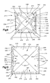
- Fig. 8 is a cutaway view of a pressure relief valve 212 constructed in accordance with a third embodiment of the present invention. Since the pressure relief valve 212 of Fig. 8 operates in substantially the same manner as the pressure relief valve 12 of Figs. 2-5, operation of the pressure relief valve 212 of Fig. 8 is not discussed below.
- the pressure relief valve 212 of Fig. 8 includes a base 214, a flexible closure member 216, and a rim 218.
- Fig. 9 is a plan view of the base 214 of the pressure relief valve 212 of Fig. 8.
- the base 214 includes a peripheral portion 220 and a support portion 222.
- the peripheral portion 220 of the base 214 illustrated in Fig. 9 is square.
- the peripheral portion 220 of the base 214 may be other shapes, such as a circle or a rectangle.
- a square-shaped central opening 224 extends through a center of the peripheral portion 220 of the base 214.
- An interior surface 226 (Fig. 8) of the peripheral portion 220 defines the opening 224.
- the interior surface 226 includes four linearly extending surfaces that collectively define the square shaped central opening 224.
- the peripheral portion 220 of the base 214 also includes an exterior surface 228, an upper surface 230, and a lower surface 232.
- the upper surface 230 of the peripheral portion 220 connects the interior and exterior surfaces 226 and 228.
- the upper surface 230 extends perpendicular to the exterior surface 228 of the peripheral portion 220 and is generally planar.
- Two bosses 234 extend outwardly of the upper surface 230 of the peripheral portion 220 of the base 214.
- the two bosses 234 are located on opposite sides of the central opening 224 relative to one another.
- Each boss 234 is centrally located on the upper surface 230 of the peripheral portion 220 between the interior and exterior surfaces 226 and 228.
- the lower surface 232 of the peripheral portion 220 also connects the interior and exterior surfaces 226 and 228.
- the lower surface 232 extends parallel to the upper surface 230 and is generally planar.
- the support portion 222 of the base 214 extends upwardly, as viewed in Fig. 8, out of a plane of the peripheral portion 220 of the base 214.
- the support portion 222 of the base 214 includes a central wall portion 240 that is square and is rotated forty-five degree relative to the square peripheral portion 220 of the base 214, as is shown in Fig. 9.
- the width of the central wall portion 240 is approximately one-fourth the width of the central opening 224 in the peripheral portion 220 of the base 214.
- the central wall portion 240 is planar and is located in a plane that extends parallel to the plane of the peripheral portion 220 of the base 214.
- the support portion 222 also includes four triangular wall portions 242 that connect the peripheral portion 220 to the central wall portion 240 of the support portion 222.
- Each triangular wall portion 242 includes a peripheral surface 244 and two side surfaces 246. The two side surfaces 246 of each of the triangular wall portions 242 have equal lengths. Thus, each triangular wall portion 242 forms either an isosceles triangle or an equilateral triangle.
- a triangular opening 248 extends through each of the triangular wall portions 242.
- each triangular wall portion 242 connects to an associated linearly extending surface of the interior surface 226 of the peripheral portion 220.
- a vertex of the side surfaces 246 of the triangular wall portion 242 is connected with a corner of the central wall portion 240 of the support portion 222 of the base 214.
- each of the triangular wall portions 242 connects the peripheral portion 220 to the central wall portion 240 of the support portion 222. Since the central wall portion 240 has a smaller width than the central opening 224 in the peripheral portion 220, the support portion 222 of the base 214 tapers inwardly as each triangular wall portion 242 extends toward the central wall portion 240.
- the support portion 222 of the base 214 also includes four triangular spacer portions 252.
- the spacer portions 252 connect adjacent triangular wall portions 242. Thus, one spacer position 252 is interposed between each pair of adjacent triangular wall portions 242.
- Each spacer portion 252 connects to a linear surface of the central wall portion 240 and extends to a corner of the interior surface 226 of the peripheral portion 220 of the base 214.
- Each spacer portion 252 is planar and is angled by forty-five degrees relative to each of the adjacent triangular wall portions 242. Since the spacer portions 252 connect adjacent triangular wall portions 242, the only openings through the support portion 222 of the base 214 are the triangular openings 248 located in the triangular wall portions 242.
- Fig. 10 illustrates the flexible closure member 216 for the pressure relief valve 212 of Fig. 8.
- the flexible closure member 216 is square and includes opposite upper and lower surfaces 254 and 256, respectively (Fig. 8).
- a width of the flexible closure member 216 is slightly less than a width of the peripheral portion 220 of the base 214, as is shown in Fig. 8.
- a plurality of slots extends through the flexible closure member 216.
- An angled slot 258 is located adjacent each corner of the flexible member 216.
- Each angled slot 258 includes first and second rectangular portions 260 and 262, respectively, that are angled ninety-degrees from one another.
- Four rectangular slots 264 are located between each of the angled slot 258.
- a slit 266 extends from the middle of each angled slot 258 to the center of the flexible closure member 216.
- the flexible closure member 216 of Fig. 10 includes four slits 266.
- the four slits 266 meet at the center of the flexible closure member 216.
- a narrow portion 268 of the flexible closure member 216 separates adjacent slots from one another.
- five narrow portions 268 are located adjacent each side of the square shaped flexible closure member 216.
- the flexible closure member 216 shown in Fig. 10 includes four flaps 270.
- One flap 270 is associated with each triangular wall portion 242 of the support portion 222 of the base 214.
- Each flap 270 of the flexible closure member 216 is triangular and includes upper and lower surfaces 272 and 274, respectively.
- Each flap 270 has an inner end 276 and an outer end 278. The inner end 276 of each flap 270 is defined between adjacent slits 266 in the flexible closure member 216. The inner end 276 narrows as it extends away from the outer end 278 and toward the center of the flexible closure member 216.
- each flap 270 is interconnected to the outer end 278 of each adjacent flap 270 so that the outer ends, collectively, form an undivided, square outer periphery 280 of the flexible closure member 216.
- Each flap 270 includes five narrow portions 268.
- the five narrow portions 268 connect the inner end 276 of the flap 270 to the outer end 278 of the flap.
- the narrow portions 268 form hinges for enabling the inner end 276 of the flap 270 to move relative to the outer end 278 of the flap 270.
- the flaps 270 of the flexible closure member 216 have a tendency to return to their original position.
- the flaps 270 of the flexible closure member 216 shown in Fig. 10 have a tendency to remain flat so that the flexible closure member 216 is planar.
- each flap 270 bends at the hinges formed by the narrow portions 268 so that the inner end 276 of each flap 270 overlays its associated triangular wall portion 242 of the base 214 to close a triangular opening 248, while the outer end 278 of each flap 270 overlays the peripheral portion 220 of the base 214.
- the tendency of the flaps 270 to return to their original position biases the flaps 270 into a closed condition closing the triangular openings 248.
- the pressure relief valve 212 operates independent of gravity and may be mounted on the vehicle in any orientation.
- the flexible closure member 216 also includes two alignment holes 282.
- the alignment holes 282 are located in the outer periphery 280 of the flexible closure member 216.
- the alignment holes 282 in the outer periphery 280 of the flexible closure member 216 illustrated in Fig. 10 are located on opposite flaps 270 from one another.
- Each of the alignment holes 282 in the flexible closure member 216 is located at a distance for receiving an associated boss 234 of the base 214.
- the rim 218 of the pressure relief valve 212 is adapted to surround the peripheral portion 220 of the base 214.
- the rim 218 has a main body portion 290 that includes an upper surface 292, a lower surface 294, and an inner surface 296.
- a pocket 298 extends into the inner surface 296 and the rim 218.
- Interior and exterior locking members 300 and 302 extend from the main body portion 290 of the rim 218.
- the interior locking member 300 includes a spacer portion 304 and a hooked portion 306.
- the spacer portion 304 extends downwardly, as viewed in Fig. 8, and slightly outwardly from the main body portion 290 of the rim 218.
- the hooked portion 306 of the interior locking member 300 is formed on an end of the spacer portion 304 opposite the main body portion 290 of the rim 218.
- the hook portion 306 extends outwardly from the spacer portion 304 and includes a sealing surface 308 for engaging and sealing against an interior surface 310 of a panel 312 (shown by dashed lines in Fig. 8) of the vehicle.
- the exterior locking member 302 of the rim 218 is a tapered member that extends downwardly, as viewed in Fig. 8, and outwardly of the main body portion 290 of the rim 218.
- the exterior locking member 302 includes upper and lower surfaces 314 and 316, respectively.
- the upper surface 314 of the exterior locking member 302 extends downwardly and outwardly from the upper surface 292 of the main body portion 290 of the rim 218.
- the lower surface 316 of the exterior locking member 302 terminates near a midpoint of the main body portion 290.
- the exterior locking member 302 narrows as it extends downwardly and outwardly from the main body portion 290 of the rim 218.
- the exterior locking member 290 is flexible and is designed to engage and seal against an exterior surface 318 of a panel 312 (shown by dashed lines in Fig. 8) of the vehicle.
- the pressure relief valve 212 of Fig. 8 is manufactured using the same two-shot molding process as described with reference to the exemplary embodiment of Figs. 2-5. Prior to the molding process, the flexible closure member 216 may stamped or thermoformed from the single piece of sheet material.
Landscapes
- Engineering & Computer Science (AREA)
- General Engineering & Computer Science (AREA)
- Mechanical Engineering (AREA)
- Physics & Mathematics (AREA)
- Thermal Sciences (AREA)
- Safety Valves (AREA)
Abstract
Each flap (74) has an outer end connected with the peripheral portion (30) of the base (18) and an inner end that is movable relative to the peripheral portion (30).
Description
- The present invention relates to a pressure relief valve and a method of manufacturing the same. More particularly, the present invention relates to a pressure relief valve for relieving pressure from a passenger compartment of a vehicle and the method of manufacturing the pressure relief valve.
- Pressure relief valves for relieving pressure from a passenger compartment of a vehicle are known. Conventional pressure relief valves include a gate that opens when a differential air pressure between the passenger compartment of the vehicle and atmosphere reaches a predetermined level. For example, when a vehicle door is slammed closed, the air pressure within the passenger compartment is likely to increase suddenly. In response to an increase in air pressure within the passenger compartment, the gate of the pressure relief valve is actuated into an open position to relieve the pressure within the passenger compartment. The conventional pressure relief valve is a one-way valve that only allows airflow from the passenger compartment to atmosphere and prevents airflow from atmosphere into the passenger compartment.
- The present invention relates to a pressure relief valve for relieving air pressure from a passenger compartment of a vehicle. The pressure relief valve comprises a base having a peripheral portion. A central opening extends through the peripheral portion. The pressure relief valve also comprises a plurality of flaps for closing the central opening of the base. Each flap has an outer end connected with the peripheral portion of the base and an inner end that is movable relative to the peripheral portion and the other flaps for enabling airflow through the central opening. Each flap has opposite surfaces against which air pressure acts. Differential air pressure acts on the opposite surfaces causing the flap to move to enable airflow through the central opening.
- The present invention also relates to a method of forming a pressure relief valve for relieving air pressure from a passenger compartment of a vehicle. During the method, a base having a peripheral portion and a central opening that extends through the peripheral portion is provided. The central opening of the base is closed with a plurality of flaps. An outer end of each flap is connected with the peripheral portion of the base. Airflow through the central opening is enabled by causing an inner end of each flap to move relative to the peripheral portion and the other flaps due to differential air pressure acting on opposite surfaces of the flap.
- The foregoing and other features of the present invention will become apparent to those skilled in the art to which the present invention relates upon reading the following description with reference to the accompanying drawings, in which:
- Fig. 1 is a partially cutaway side view of a vehicle including a pressure relief valve constructed in accordance with the present invention;
- Fig. 2 is a perspective view of a pressure relief valve constructed in accordance with the present invention;
- Fig. 3 is a plan view of the pressure relief valve of Fig. 2;
- Fig. 4 is a view taken along line 4-4 in Fig. 3;
- Fig. 5 is an exploded perspective view of the pressure relief valve of Fig 2;
- Fig. 6 is a plan view of a pressure relief valve constructed in accordance with a second embodiment of the present invention;
- Fig. 7 is a plan view of a portion of the pressure relief valve of Fig. 6;
- Fig. 8 is a cutaway view of a pressure relief valve constructed in accordance with a third embodiment of the present invention;
- Fig. 9 is a plan view of a first portion of the pressure relief valve of Fig. 8; and
- Fig. 10 is a plan view of a second portion of the pressure relief valve of Fig. 8.
-
- Fig. 1 is a side view of a
vehicle 10 including apressure relief valve 12 constructed in accordance with the present invention. Thepressure relief valve 12 separates thepassenger compartment 14 of thevehicle 10 fromatmosphere 16 and is operable to relieve pressure from the passenger compartment of the vehicle. In Fig. 1, thepressure relief valve 12 is located in the trunk of thevehicle 10. Thepressure relief valve 12 may be located at other location on thevehicle 10. - Fig. 2 illustrates a perspective view of an exemplary embodiment of a
pressure relief valve 12 constructed in accordance with the present invention. An exploded perspective view of thepressure relief valve 12 of Fig. 2 is shown in Fig. 5. Thepressure relief valve 12 includes abase 18, aflexible closure member 20, and arim 22. - The
base 18 includes aperipheral portion 30 and asupport portion 32. Theperipheral portion 30 of thebase 18 illustrated in Fig. 5 is annular. Theperipheral portion 30 of thebase 18 may be a shape other than annular. For example, theperipheral portion 30 may be elliptical or rectangular. - As shown in Fig. 4, the
peripheral portion 30 includes radial inner andouter surfaces lower surfaces surfaces peripheral portion 30 collectively define a rectangular cross-section of theperipheral portion 30. The radialouter surface 36 of theperipheral portion 30 defines a diameter of thebase 18 and is centered on axis A, shown in Fig. 5. The radialinner surface 34 of theperipheral portion 30 extends parallel to and is coaxial with the radialouter surface 36. The radialinner surface 34 defines acentral opening 42 that extends through theperipheral portion 30 of thebase 18. Thecentral opening 42 of thebase 18 illustrated in Fig. 4 has a diameter of approximately eighty-five percent the diameter of the base. - The
upper surface 38 of theperipheral portion 30 connects the radial inner andouter surfaces bosses 44 extend outwardly of theupper surface 38 of theperipheral portion 30 of thebase 18. The twobosses 44 illustrated in Fig. 5 align with one another on opposite sides of axis A. Eachboss 44 is centrally located on theupper surface 38 of theperipheral portion 30 between the radial inner andouter surfaces lower surface 40 of theperipheral portion 30 also connects the radial inner andouter surfaces lower surface 40 extends parallel to theupper surface 38 and radially relative to axis A. - The
support portion 32 of thebase 18 includes acentral portion 48 and a plurality of radially extendingbranches 50. Thesupport portion 32 for thebase 18 illustrated in Fig. 5 includes four radially extendingbranches 50. Thecentral portion 48 is located at the center of thecentral opening 42. The four radially extending branches connect thecentral portion 48 of thesupport portion 32 to theperipheral portion 30. - Each radially extending
branch 50 of the support portion of the base includes anupper surface 52 and a lower surface (not shown) and first andsecond side surfaces upper surface 52 of eachbranch 50 aligns with and extends parallel to theupper surface 38 of theperipheral portion 30 of thebase 18. Likewise, the lower surface of eachbranch 50 aligns with and extends parallel to thelower surface 40 of theperipheral portion 30 of thebase 18. The first andsecond side surfaces inner surface 34 of theperipheral portion 30 of thebase 18. Eachbranch 50 of thesupport portion 32 has a rectangular cross-section. - The
branches 50 of thesupport portion 32 of the base 18 divide thecentral opening 42 into a plurality offlow openings 58. The number offlow openings 58 is equal to the number ofbranches 50. Thus, the fourbranches 50 of thesupport portion 32 of Fig. 5 divide thecentral opening 42 into fourflow openings 58. Three surfaces define each flow opening 58 in thebase 18. The three surfaces include a portion of the radialinner surface 34 of theperipheral portion 30, afirst side surface 54 of onebranch 50, and asecond side surface 56 of anadjacent branch 50. Thus, the fourflow openings 58 in thebase 18 are sectors of thecentral opening 42 that extends through theperipheral portion 30 of thebase 18. - The
flexible closure member 20 of thepressure relief valve 12 is circular and includes opposite upper andlower surfaces flexible closure member 20 is located on axis A. - Four
arcuate slots 68 extend through theflexible closure member 20 illustrated in Fig. 5. The fourarcuate slots 68 are spaced equidistance from axis A and are positioned in a spaced array about axis A. A distance betweenarcuate slots 68 located on opposite sides of axis A is approximately eighty-five percent of the diameter of theflexible closure member 20. Aslit 70 extends from the middle of eacharcuate slot 68 to the center of theflexible closure member 20. Thus, theflexible closure member 20 of Fig. 5 includes fourslits 70. The fourslits 70 meet with one another at axis A. A narrow portion 72 (Fig. 5) of theflexible closure member 20 separates adjacentarcuate slots 68 from one another. Theflexible closure member 20 of Fig. 5 includes fournarrow portions 72. - The
flexible closure member 20 includes a plurality offlaps 74. Theflexible closure member 20 shown in Figs. 2, 3, and 5 includes fourflaps 74. Eachflap 74 forms a sector of theflexible closure member 20 and includes upper andlower surfaces flap 74 has an inner end 80 (Fig. 5) and an outer end 82 (Fig. 5). Theinner end 80 of eachflap 74 is defined betweenadjacent slits 70 in theflexible closure member 20. Theinner end 80 narrows as it extends away from theouter end 82 and toward axis A. Theinner end 80 of eachflap 74 is defined between first andsecond side portions exemplary flap 74 in Fig. 5. Theouter end 82 of eachflap 74 is interconnected to theouter end 82 of eachadjacent flap 74 so that the outer ends of the plurality of flaps, collectively, form an undividedouter periphery 90 of theflexible closure member 20. One of the fournarrow portions 72 is associated with eachflap 74 and connects theinner end 80 of theflap 74 to theouter end 82 of the flap. Thenarrow portion 72 forms a hinge for enabling theinner end 80 of theflap 74 to move relative to theouter end 82 of the flap. - The
flexible closure member 20 also includes two alignment holes 92. The alignment holes 92 are located in theouter periphery 90 of theflexible closure member 20. The alignment holes 92 of in theflexible closure member 20 illustrated in Fig. 5 align with one another on opposite sides of axis A and are aligned with two of theslits 70 in the flexible closure member. Each of the alignment holes 92 in theflexible closure member 20 is located at a distance from axis A to receive an associatedboss 44 of thebase 18. - The
rim 22 of thepressure relief valve 12 has an annular main body portion 98 (Fig. 4) that is centered on axis A. Themain body portion 98 includes anupper surface 100, alower surface 102, and an annularinner surface 104. A diameter of the annularinner surface 104 is less than the diameter of the radialouter surface 36 of theperipheral portion 30 of thebase 18. The diameter of the annularinner surface 104 is greater than the diameter between radially outermost portions of thearcuate slots 68 of theflexible closure member 20. - An
annular pocket 106 extends into the annularinner surface 104 of themain body portion 98 and therim 22. Theannular pocket 106 is defined between alower surface 108 and anupper surface 110. An annularinner surface 112 defines a bottom of theannular pocket 106. - Interior and
exterior locking members main body portion 98 of therim 22. Theinterior locking member 116 is annular and includes aspacer portion 120 and ahooked portion 122. Thespacer portion 120 extends downwardly, as viewed in Fig. 4, and slightly radially outwardly from themain body portion 98 of therim 22. The hookedportion 122 of theinterior locking member 116 is formed on an end of thespacer portion 120 opposite themain body portion 98 of therim 22. Thehook portion 122 extends radially outwardly from thespacer portion 120 and includes asurface 124 for engaging and sealing against aninterior surface 126 of a panel 128 (shown by dashed lines in Fig. 4) of thevehicle 10. - The
exterior locking member 118 of the rim is an annular tapered member that extends downwardly, as viewed in Fig. 4, and radially outwardly of themain body portion 98 of therim 22. Theexterior locking member 118 includes upper andlower surfaces upper surface 130 of theexterior locking member 118 extends downwardly and radially outwardly from theupper surface 100 of themain body portion 98 of therim 22. Thelower surface 132 of theexterior locking member 118 terminates near a midpoint of themain body portion 98. Theexterior locking member 118 narrows as it extends downwardly and radially outwardly from themain body portion 98 of therim 22. Theexterior locking member 118 is flexible and is designed to engage and seal against anexterior surface 134 of a panel 128 (shown by dashed lines in Fig. 4) of thevehicle 10. - The
pressure relief valve 12 of the present invention is manufactured in a two-shot molding process. Prior to the molding process, theflexible closure member 20 is manufactured. Theflexible closure member 20 may be made from a Mylar film, polyester, or a polycarbonate-based material. Preferably, theflexible closure member 20 is formed from a single piece of sheet material having a thickness in the range of 3-7 thousandths of an inch. Theflexible closure member 20 may be stamped or thermoformed from the single piece of sheet material. - The two-shot molding process may be performed in a single two-shot injection molding machine or, alternatively, may be performed in two separate, one-shot injection molding machines. The first shot of the injection molding process forms the
base 18 of thepressure relief valve 12. Thebase 18 is formed as a monolithic structure that is free from any connecting devices or fasteners. Thebase 18 is formed from a homogenous material, preferably a polypropylene or thermoplastic and has a uniform density throughout. - After the
base 18 is molded, theflexible closure member 20 is placed on thebase 18. Theflexible closure member 20 is placed over the base 18 so that the alignment holes 92 in theflexible closure member 20 receive thebosses 44 on theupper surface 38 of theperipheral portion 30 of thebase 18. When the alignment holes 92 in theflexible closure member 20 receive thebosses 44 of thebase 18, theouter periphery 90 of theflexible closure member 20 overlies theupper surface 38 of theperipheral portion 30 of thebase 18. As a result, eachflap 74 of theflexible closure member 20 covers or closes an associated flow opening 58 in thebase 18 and theslits 70 that separateadjacent flaps 74 of theflexible closure member 20 are positioned on anupper surface 38 of an associatedbranch 50 of thesupport portion 32 of thebase 18, as is shown in Figs. 2 and 3. When aslit 70 that separatesadjacent flaps 74 of theflexible closure member 20 is positioned on anupper surface 38 of an associatedbranch 50, theupper surface 38 of the associatedbranch 50 also supportsadjacent side portions - The second shot of the injection molding process forms the
rim 22 of thepressure relief valve 12. Therim 22 is also formed as a monolithic structure that is free from any connecting devices or fasteners. Therim 22 is formed from a homogenous material, preferably a thermoplastic elastomer, and has a uniform density throughout. An exemplary thermoplastic elastomer would be a TPV (thermoplastic vulcanizate) such as SANTOPRENE. - The
peripheral portion 30 of thebase 18 and theouter periphery 90 of theflexible closure member 20, which at this time overlies theupper surface 38 of theperipheral portion 30 of thebase 18, form a portion of a mold for forming therim 22. Thus, the material used to form therim 22 must have a melting point that is lower than the melting points of the materials of thebase 18 and theflexible closure member 20. - The
rim 22 is molded directly onto theperipheral portion 30 of thebase 18 andouter periphery 90 of theflexible closure member 20. Therim 22 fixedly secures theouter periphery 90 of theflexible closure member 20, i.e., the outer ends 82 of theflaps 74, relative to theperipheral portion 30 of thebase 18. The moldedrim 22 chemically bonds to theperipheral portion 30 of thebase 18. Alternatively, a mechanical bond may be formed between therim 22 and theperipheral portion 30 of the base 18 using known methods. - As shown in Fig. 4, the
rim 22 terminates at the annularinner surface 104 in a position radially outward of thearcuate slots 68 of theflexible closure member 20. The manufacture of thepressure relief valve 12 of the present invention is complete after therim 22 is formed. - The
pressure relief valve 12 of the present invention acts as a check valve or one-way valve. Thepressure relief valve 12 enables airflow from thepassenger compartment 14 of thevehicle 10 toatmosphere 16, but prevents airflow fromatmosphere 16 into thepassenger compartment 14 of thevehicle 10. By preventing airflow fromatmosphere 16 into thepassenger compartment 14 of thevehicle 10, thepressure relief valve 12 of the present invention helps to prevent atmospheric noise, dust, and carbon monoxide from entering thepassenger compartment 14 of thevehicle 10. - The
pressure relief valve 12 of the present invention is operable in response to differential air pressure between thepassenger compartment 14 of thevehicle 10 andatmosphere 16. Fig. 4 illustrates the location of thepassenger compartment 14 andatmosphere 16 relative to thepressure relief valve 12 when mounted to apanel 128 of thevehicle 10. Fig. 4 also illustrates thepressure relief valve 12 in a closed condition. Theflaps 74 of theflexible closure member 20 have a tendency to remain flat. Thus, when air pressure within thepassenger compartment 14 of thevehicle 10 andatmospheric pressure 16 are equal, thepressure relief valve 12 will remain in a closed condition. - When atmospheric pressure increased above the air pressure within the
passenger compartment 14 of thevehicle 10, the atmospheric pressure acts downwardly, as viewed in Fig. 4, against theflaps 74 of theflexible closure member 20. Since eachflap 74 is supported on theupper surfaces 52 ofadjacent branches 50 of thesupport portion 32 of thebase 18, the inner ends 80 of theflaps 74 of theflexible closure member 20 remain in the closed condition and do not move relative to thebase 18. As a result, airflow from theatmosphere 16 into thepassenger compartment 14 of thevehicle 10 is prevented. - When the air pressure within the
passenger compartment 14 of thevehicle 10 increased above atmospheric pressure, the air pressure within thepassenger compartment 14 acts upwardly, as viewed in Fig. 4, against theflaps 74 of theflexible closure member 20. When the air pressure within thepassenger compartment 14 is greater than atmospheric pressure by a predetermined level, i.e., a level to overcome the tendency of theflaps 74 to remain flat, the inner ends 80 of theflaps 74 move upwardly, as viewed in Fig. 4, to enable airflow from thepassenger compartment 14 toatmosphere 16. When the inner ends 80 of theflaps 74 move to enable airflow from thepassenger compartment 14 toatmosphere 16, theflaps 74 are in an open condition. Dashed lines in Fig. 4 illustrate the open condition of theflaps 74. When the differential air pressure between thepassenger compartment 14 of thevehicle 10 andatmosphere 16 falls below the predetermined level, the tendency of theflaps 74 to remain flat causes theflaps 74 to move back into the closed condition. The tendency of theflaps 74 to remain flat, biases theflaps 74 into the closed condition. As a result, thepressure relief valve 12 operates independent of gravity and may be mounted on thevehicle 10 in any orientation. - Fig. 6 is a plan view of a pressure relief valve 12' constructed in accordance with a second embodiment of the present invention. Structure of the pressure relief valve 12' of Fig. 6 that are similar to or perform the same function as structure of the
pressure relief valve 12 illustrated in Figs. 2-5 are referred to using the same reference numbers. - The pressure relief valve 12' of Fig. 6 is identical to the
pressure relief valve 12 of Figs. 2-5 with the exception that thesupport portion 32 of thebase 18 has been modified. Fig. 7 is a plan view of thebase 18 for the pressure relief valve 12' of Fig. 6. Thesupport portion 32 of thebase 18 of the pressure relief valve 12' of Fig. 6 includes anannular support portion 138 that is located radially outwardly of thecentral portion 48 and that interconnects the plurality of radially extendingbranches 50. - The
annular support portion 138 is coaxial with theperipheral portion 30 of thebase 18 and includes an upper surface 140 (Fig. 7) that extends parallel to and aligns with theupper surfaces 52 of each of theradially extending branches 50. Theannular support portion 138 divides each flow opening 58 into a sector shaped flow opening 142 and an arcuate flow opening 144. Theannual support portion 138 of thebase 18 provides additional support for theinner end 80 of eachflap 74 when the flap is in the closed condition and provides further resistance against airflow fromatmosphere 16 into thepassenger compartment 14 of thevehicle 10. - Fig. 8 is a cutaway view of a
pressure relief valve 212 constructed in accordance with a third embodiment of the present invention. Since thepressure relief valve 212 of Fig. 8 operates in substantially the same manner as thepressure relief valve 12 of Figs. 2-5, operation of thepressure relief valve 212 of Fig. 8 is not discussed below. - The
pressure relief valve 212 of Fig. 8 includes abase 214, aflexible closure member 216, and arim 218. Fig. 9 is a plan view of thebase 214 of thepressure relief valve 212 of Fig. 8. Thebase 214 includes aperipheral portion 220 and asupport portion 222. - The
peripheral portion 220 of the base 214 illustrated in Fig. 9 is square. Alternatively, theperipheral portion 220 of the base 214 may be other shapes, such as a circle or a rectangle. A square-shapedcentral opening 224 extends through a center of theperipheral portion 220 of thebase 214. An interior surface 226 (Fig. 8) of theperipheral portion 220 defines theopening 224. Theinterior surface 226 includes four linearly extending surfaces that collectively define the square shapedcentral opening 224. Theperipheral portion 220 of the base 214 also includes anexterior surface 228, anupper surface 230, and alower surface 232. - The
upper surface 230 of theperipheral portion 220 connects the interior andexterior surfaces upper surface 230 extends perpendicular to theexterior surface 228 of theperipheral portion 220 and is generally planar. Twobosses 234 extend outwardly of theupper surface 230 of theperipheral portion 220 of thebase 214. The twobosses 234 are located on opposite sides of thecentral opening 224 relative to one another. Eachboss 234 is centrally located on theupper surface 230 of theperipheral portion 220 between the interior andexterior surfaces lower surface 232 of theperipheral portion 220 also connects the interior andexterior surfaces lower surface 232 extends parallel to theupper surface 230 and is generally planar. - The
support portion 222 of thebase 214 extends upwardly, as viewed in Fig. 8, out of a plane of theperipheral portion 220 of thebase 214. Thesupport portion 222 of thebase 214 includes acentral wall portion 240 that is square and is rotated forty-five degree relative to the squareperipheral portion 220 of thebase 214, as is shown in Fig. 9. The width of thecentral wall portion 240 is approximately one-fourth the width of thecentral opening 224 in theperipheral portion 220 of thebase 214. Thecentral wall portion 240 is planar and is located in a plane that extends parallel to the plane of theperipheral portion 220 of thebase 214. - The
support portion 222 also includes fourtriangular wall portions 242 that connect theperipheral portion 220 to thecentral wall portion 240 of thesupport portion 222. Eachtriangular wall portion 242 includes aperipheral surface 244 and two side surfaces 246. The twoside surfaces 246 of each of thetriangular wall portions 242 have equal lengths. Thus, eachtriangular wall portion 242 forms either an isosceles triangle or an equilateral triangle. Atriangular opening 248 extends through each of thetriangular wall portions 242. - The
peripheral surface 244 of eachtriangular wall portion 242 connects to an associated linearly extending surface of theinterior surface 226 of theperipheral portion 220. A vertex of the side surfaces 246 of thetriangular wall portion 242 is connected with a corner of thecentral wall portion 240 of thesupport portion 222 of thebase 214. Thus, each of thetriangular wall portions 242 connects theperipheral portion 220 to thecentral wall portion 240 of thesupport portion 222. Since thecentral wall portion 240 has a smaller width than thecentral opening 224 in theperipheral portion 220, thesupport portion 222 of the base 214 tapers inwardly as eachtriangular wall portion 242 extends toward thecentral wall portion 240. - The
support portion 222 of the base 214 also includes fourtriangular spacer portions 252. Thespacer portions 252 connect adjacenttriangular wall portions 242. Thus, onespacer position 252 is interposed between each pair of adjacenttriangular wall portions 242. Eachspacer portion 252 connects to a linear surface of thecentral wall portion 240 and extends to a corner of theinterior surface 226 of theperipheral portion 220 of thebase 214. Eachspacer portion 252 is planar and is angled by forty-five degrees relative to each of the adjacenttriangular wall portions 242. Since thespacer portions 252 connect adjacenttriangular wall portions 242, the only openings through thesupport portion 222 of the base 214 are thetriangular openings 248 located in thetriangular wall portions 242. - Fig. 10 illustrates the
flexible closure member 216 for thepressure relief valve 212 of Fig. 8. Theflexible closure member 216 is square and includes opposite upper andlower surfaces flexible closure member 216 is slightly less than a width of theperipheral portion 220 of thebase 214, as is shown in Fig. 8. - A plurality of slots extends through the
flexible closure member 216. Anangled slot 258 is located adjacent each corner of theflexible member 216. Eachangled slot 258 includes first and secondrectangular portions rectangular slots 264 are located between each of theangled slot 258. Aslit 266 extends from the middle of eachangled slot 258 to the center of theflexible closure member 216. Thus, theflexible closure member 216 of Fig. 10 includes fourslits 266. The fourslits 266 meet at the center of theflexible closure member 216. Anarrow portion 268 of theflexible closure member 216 separates adjacent slots from one another. Thus, fivenarrow portions 268 are located adjacent each side of the square shapedflexible closure member 216. - The
flexible closure member 216 shown in Fig. 10 includes fourflaps 270. Oneflap 270 is associated with eachtriangular wall portion 242 of thesupport portion 222 of thebase 214. Eachflap 270 of theflexible closure member 216 is triangular and includes upper andlower surfaces flap 270 has aninner end 276 and anouter end 278. Theinner end 276 of eachflap 270 is defined betweenadjacent slits 266 in theflexible closure member 216. Theinner end 276 narrows as it extends away from theouter end 278 and toward the center of theflexible closure member 216. Theouter end 278 of eachflap 270 is interconnected to theouter end 278 of eachadjacent flap 270 so that the outer ends, collectively, form an undivided, squareouter periphery 280 of theflexible closure member 216. Eachflap 270 includes fivenarrow portions 268. The fivenarrow portions 268 connect theinner end 276 of theflap 270 to theouter end 278 of the flap. Thenarrow portions 268 form hinges for enabling theinner end 276 of theflap 270 to move relative to theouter end 278 of theflap 270. - The
flaps 270 of theflexible closure member 216 have a tendency to return to their original position. For example, theflaps 270 of theflexible closure member 216 shown in Fig. 10 have a tendency to remain flat so that theflexible closure member 216 is planar. When assembled onto thebase 214, eachflap 270 bends at the hinges formed by thenarrow portions 268 so that theinner end 276 of eachflap 270 overlays its associatedtriangular wall portion 242 of the base 214 to close atriangular opening 248, while theouter end 278 of eachflap 270 overlays theperipheral portion 220 of thebase 214. The tendency of theflaps 270 to return to their original position biases theflaps 270 into a closed condition closing thetriangular openings 248. As a result, thepressure relief valve 212 operates independent of gravity and may be mounted on the vehicle in any orientation. - The
flexible closure member 216 also includes two alignment holes 282. The alignment holes 282 are located in theouter periphery 280 of theflexible closure member 216. The alignment holes 282 in theouter periphery 280 of theflexible closure member 216 illustrated in Fig. 10 are located onopposite flaps 270 from one another. Each of the alignment holes 282 in theflexible closure member 216 is located at a distance for receiving an associatedboss 234 of thebase 214. - The
rim 218 of thepressure relief valve 212 is adapted to surround theperipheral portion 220 of thebase 214. Therim 218 has amain body portion 290 that includes anupper surface 292, alower surface 294, and aninner surface 296. Apocket 298 extends into theinner surface 296 and therim 218. - Interior and
exterior locking members main body portion 290 of therim 218. Theinterior locking member 300 includes aspacer portion 304 and ahooked portion 306. Thespacer portion 304 extends downwardly, as viewed in Fig. 8, and slightly outwardly from themain body portion 290 of therim 218. The hookedportion 306 of theinterior locking member 300 is formed on an end of thespacer portion 304 opposite themain body portion 290 of therim 218. Thehook portion 306 extends outwardly from thespacer portion 304 and includes a sealingsurface 308 for engaging and sealing against aninterior surface 310 of a panel 312 (shown by dashed lines in Fig. 8) of the vehicle. - The
exterior locking member 302 of therim 218 is a tapered member that extends downwardly, as viewed in Fig. 8, and outwardly of themain body portion 290 of therim 218. Theexterior locking member 302 includes upper andlower surfaces upper surface 314 of theexterior locking member 302 extends downwardly and outwardly from theupper surface 292 of themain body portion 290 of therim 218. Thelower surface 316 of theexterior locking member 302 terminates near a midpoint of themain body portion 290. Theexterior locking member 302 narrows as it extends downwardly and outwardly from themain body portion 290 of therim 218. Theexterior locking member 290 is flexible and is designed to engage and seal against anexterior surface 318 of a panel 312 (shown by dashed lines in Fig. 8) of the vehicle. - The
pressure relief valve 212 of Fig. 8 is manufactured using the same two-shot molding process as described with reference to the exemplary embodiment of Figs. 2-5. Prior to the molding process, theflexible closure member 216 may stamped or thermoformed from the single piece of sheet material. - From the above description of the invention, those skilled in the art will perceive improvements, changes and modifications. Such improvements, changes and modifications within the skill of the art are intended to be covered by the appended claims.
Claims (24)
- A pressure relief valve for relieving air pressure from a passenger compartment of a vehicle, the pressure relief valve comprising:a base having a peripheral portion, a central opening extending through the peripheral portion; anda plurality of flaps for closing the central opening of the base, each flap having an outer end connected with the peripheral portion of the base and an inner end that is movable relative to the peripheral portion and the other flaps for enabling airflow through the central opening;each flap having opposite surfaces against which air pressure acts, differential air pressure acting on the opposite surfaces causing the flap to move to enable airflow through the central opening.
- The pressure relief valve of claim 1 wherein the base includes a support portion that divides the central opening into a plurality of flow openings, each flap of the plurality of flaps being associated with at least one flow opening for closing the at least one flow opening.
- The pressure relief valve of claim 2 wherein the support portion of the base supports the inner end of each flap in a closed condition closing the at least one flow opening, the support portion enabling movement of the inner end of each flap in a first direction relative to the support portion and preventing movement of the inner end in a second direction, opposite the first direction, relative to the support portion for enabling airflow through the at least one flow opening in only the first direction.
- The pressure relief valve of claim 3 wherein the base, including the peripheral portion and the support portion, is a monolithic structure that is free from any connecting devices, is formed from a homogenous material, and has a uniform density throughout.
- The pressure relief valve of claim 1 wherein each flap of the plurality of flaps includes at least one hinge for connecting the inner end of the flap with the outer end of the flap, the at least one hinge enabling movement of the inner end relative to the outer end.
- The pressure relief valve of claim 5 wherein the at least one hinge is at least one narrow portion of material formed between slots in the flap.
- The pressure relief valve of claim 1 wherein each flap of the plurality of flaps is biased into a closed condition for, collectively, closing the central opening so that the pressure relief valve operates independent of gravity.
- The pressure relief valve of claim 1 wherein the plurality of flaps are formed in a single sheet of flexible material, the outer ends of the plurality of flaps being interconnected to collectively form an undivided outer periphery of the sheet of flexible material, the inner ends of the plurality of flaps forming a central portion of the sheet of flexible material and being movable relative to the outer periphery.
- The pressure relief valve of claim 8 wherein the peripheral portion of the base includes first alignment members and the outer periphery of the sheet of flexible material includes second alignment members that are adapted to cooperate with the first alignment members for positioning the sheet of flexible material relative to the base.
- The pressure relief valve of claim 1 further including a rim molded onto the peripheral portion of the base for fixedly securing the outer end of each flap to the peripheral portion of the base.
- The pressure relief valve of claim 10 wherein the rim includes a locking portion adapted to secure the pressure relief valve to a panel of the vehicle, the locking portion further being adapted to seal against the panel of the vehicle.
- The pressure relief valve of claim 10 wherein the base is a molded base.
- A method of forming a pressure relief valve for relieving air pressure from a passenger compartment of a vehicle, the method comprising the steps of:providing a base having a peripheral portion and a central opening that extends through the peripheral portion;closing the central opening of the base with a plurality of flaps;connecting an outer end of each flap with the peripheral portion of the base; andenabling airflow through the central opening by causing an inner end of each flap to move relative to the peripheral portion and the other flaps due to differential air pressure acting on opposite surfaces of the flap.
- The method of claim 13 wherein the step of providing a base having a peripheral portion and a central opening further includes the step of injection molding the base.
- The method of claim 13 wherein the step of providing a base having a peripheral portion and a central opening further includes the steps of providing a support portion of the base that divides the central opening into a plurality of flow openings, and associating a flap of the plurality of flaps with at least one flow opening for closing the at least one flow opening and for moving to enable airflow through the at least one flow opening.
- The method of claim 15 further including the steps of supporting, with the support portion of the base, the inner end of each flap in a closed condition closing the at least one flow opening, enabling movement of the inner end of each flap in a first direction relative to the support portion, and preventing movement of the inner end of each flap in a second direction, opposite the first direction, relative to the support portion for enabling airflow through the at least one flow opening in only the first direction.
- The method of claim 15 wherein the steps of providing a base having a peripheral portion and providing a support portion on the base further include the step of molding the base, including the peripheral portion and the support portion, from a homogenous material so that the base is a monolithic structure that is free from any connecting devices and has a uniform density throughout.
- The method of claim 13 wherein the step of closing the central opening of the base with a plurality of flaps further includes the step of forming at least one hinge in each flap to connect the inner end of the flap with the outer end of the flap for enabling movement of the inner end relative to the outer end.
- The method of claim 18 wherein the step of forming at least one hinge in each flap includes the step of cutting slots through the flap to form at least one narrow portion of material between slots.
- The method of-claim 13 wherein the step of closing the central opening of the base with a plurality of flaps further includes the step of forming the plurality of flaps from a material having a tendency to return the flaps to a closed condition closing the central opening of the base so as to form a pressure relief valve that is independent of gravity.
- The method of claim 13 wherein the step of closing the central opening of the base with a plurality of flaps further includes the steps of forming the plurality of flaps in a single sheet of flexible material, maintaining an outer periphery of the sheet of flexible material undivided so that the outer ends of the plurality of flaps are interconnected, and forming the inner ends of the plurality of flaps in a central portion of the sheet of flexible material.
- The method of claim 21 further including the steps of providing first alignment members on the peripheral portion of the base, and providing second alignment members, that are adapted to cooperate with the first alignment members for positioning the sheet of flexible material relative to the base, on the outer periphery of the sheet of flexible material.
- The method of claim 13 further including the step of molding a rim onto the peripheral portion of the base for fixedly securing the outer end of each flap to the peripheral portion of the molded base.
- The method of claim 23 wherein the step of molding a rim further includes the step of forming a locking portion on the rim that is adapted to secure the pressure relief valve to a panel of the vehicle and is further adapted to seal against the panel of the vehicle.
Applications Claiming Priority (2)
| Application Number | Priority Date | Filing Date | Title |
|---|---|---|---|
| US686212 | 1996-07-23 | ||
| US10/686,212 US7302962B2 (en) | 2003-10-15 | 2003-10-15 | Vehicle pressure relief valve having peripherally secured flaps and method of manufacturing the same |
Publications (1)
| Publication Number | Publication Date |
|---|---|
| EP1524140A1 true EP1524140A1 (en) | 2005-04-20 |
Family
ID=34377636
Family Applications (1)
| Application Number | Title | Priority Date | Filing Date |
|---|---|---|---|
| EP20040024317 Withdrawn EP1524140A1 (en) | 2003-10-15 | 2004-10-12 | Vehicle pressure relief valve |
Country Status (3)
| Country | Link |
|---|---|
| US (1) | US7302962B2 (en) |
| EP (1) | EP1524140A1 (en) |
| MX (1) | MXPA04010119A (en) |
Cited By (5)
| Publication number | Priority date | Publication date | Assignee | Title |
|---|---|---|---|---|
| WO2014209480A1 (en) * | 2013-06-26 | 2014-12-31 | Illinois Tool Works Inc. | Closing plug for an opening in a body structure of an automobile |
| CN105008159A (en) * | 2013-03-14 | 2015-10-28 | Trw汽车美国有限责任公司 | Pressure relief valve |
| CN105751854A (en) * | 2015-01-07 | 2016-07-13 | Trw车辆电气与零件有限公司 | Venting Device |
| AU2018327222B2 (en) * | 2018-05-02 | 2020-09-17 | St Engineering Innosparks Pte. Ltd. | Multi-flap valve for a respiratory device |
| IT202200006131A1 (en) * | 2022-03-29 | 2023-09-29 | Condevo S P A | CLAPET CHECK VALVE AND HEAT EXCHANGE CELL FOR CONDENSING BOILER FOR A HEATING SYSTEM |
Families Citing this family (30)
| Publication number | Priority date | Publication date | Assignee | Title |
|---|---|---|---|---|
| US7832429B2 (en) * | 2004-10-13 | 2010-11-16 | Rheonix, Inc. | Microfluidic pump and valve structures and fabrication methods |
| JP4652121B2 (en) * | 2005-05-18 | 2011-03-16 | 日東電工株式会社 | Ventilation member and ventilation casing using the same |
| US20070175523A1 (en) * | 2006-01-31 | 2007-08-02 | Levey Kenneth R | Pressure relief assembly |
| US8414368B2 (en) * | 2007-01-23 | 2013-04-09 | Munters Corporation | Fan damper |
| DE102007013869A1 (en) * | 2007-03-20 | 2008-09-25 | Behr Gmbh & Co. Kg | Flap assembly, in particular for a motor vehicle air conditioning |
| CN101889163B (en) * | 2007-10-08 | 2014-06-11 | 耶斯·图戈德·格拉姆 | elastic valve |
| DE202007014663U1 (en) * | 2007-10-19 | 2008-02-21 | Trw Automotive Electronics & Components Gmbh | venting device |
| CN102553097A (en) * | 2007-11-27 | 2012-07-11 | 3M创新有限公司 | Face mask with unidirectional valve |
| US8267162B1 (en) * | 2008-09-16 | 2012-09-18 | Standard Motor Products | Bi-directional pressure relief valve for a plate fin heat exchanger |
| GB0820978D0 (en) * | 2008-11-17 | 2008-12-24 | Reckitt & Colman Overseas | A relief valve |
| US20100269913A1 (en) * | 2009-04-22 | 2010-10-28 | Steven J. Hollinger | Gravity-assisted drain valve for restricting intake of mildew spores |
| JP5667628B2 (en) * | 2009-07-08 | 2015-02-12 | エアロクライン・エイビイ | Diaphragm device for check valve, check valve including diaphragm device and check valve system |
| DE102009026222B4 (en) * | 2009-07-22 | 2014-01-23 | Woco Industrietechnik Gmbh | valve assembly |
| US8616944B2 (en) * | 2009-09-04 | 2013-12-31 | GM Global Technology Operations LLC | Pressure relief valve for a vehicle body |
| DE102012100198B4 (en) * | 2012-01-11 | 2013-10-10 | WEGU Holding GmbH | One-piece plastic molded part with a flap free of play in a closed position and its arrangement in the engine compartment of a motor vehicle |
| US10543736B2 (en) * | 2012-10-17 | 2020-01-28 | Ford Global Technologies, Llc | Vehicle cabin air management |
| US9834064B2 (en) | 2013-01-14 | 2017-12-05 | Brose Fahrzeugteile Gmbh & Co. Kg, Wurzburg | Vehicle ventilation module and device |
| US20140273784A1 (en) * | 2013-03-13 | 2014-09-18 | Ford Global Technologies, Llc | Air extractor to reduce closing effort |
| US20160281870A1 (en) * | 2015-03-26 | 2016-09-29 | GM Global Technology Operations LLC | Reverse pressure relief valve to reduce door closing velocity/effort |
| KR101863427B1 (en) * | 2016-02-02 | 2018-06-01 | 한국수력원자력 주식회사 | Gas Collection Device for Trapping Accumulation Gas in Pipes |
| DE102016011597B4 (en) | 2016-09-27 | 2024-12-05 | Dräger Safety AG & Co. KGaA | Directional valve, in particular for respiratory gases, and method for its manufacture |
| FI20175091L (en) * | 2017-02-02 | 2018-08-03 | Ferramill Oy | Grouting tools and grouting procedure |
| US10167967B2 (en) | 2017-02-15 | 2019-01-01 | Nissan North America, Inc. | Airbox drain valve |
| US10435078B2 (en) * | 2017-02-15 | 2019-10-08 | Nissan North America, Inc. | Airbox drain syphon tube valve |
| WO2023050016A1 (en) | 2021-10-01 | 2023-04-06 | Markdom International Inc. | Injection molded vehicle compartment pressure relief valve |
| US12128740B2 (en) | 2021-12-10 | 2024-10-29 | Markdom International Inc. | Vehicle accessory apparatus with incomplete assembly indicator |
| DE102023123330A1 (en) * | 2022-09-15 | 2024-03-21 | Illinois Tool Works Inc. | Device for sealingly connecting to an opening of a support component |
| CN115899333B (en) * | 2022-12-07 | 2026-03-03 | 大连船舶重工集团有限公司 | Air jet hole plug with unidirectional sealing function |
| CN116811531B (en) * | 2023-06-30 | 2025-12-12 | 浙江吉利控股集团有限公司 | A vehicle body pressure relief valve regulating device, method and vehicle |
| USD1104216S1 (en) | 2023-10-05 | 2025-12-02 | Illinois Tool Works Inc. | Drain valve |
Citations (4)
| Publication number | Priority date | Publication date | Assignee | Title |
|---|---|---|---|---|
| DE1550265A1 (en) * | 1966-10-04 | 1969-07-31 | Walter Gondrom | Valve |
| CH572179A5 (en) * | 1973-08-28 | 1976-01-30 | Kyburz Hans | Non-return valve with flexible shutter - shutter bears against ported walls of taper insert and held by flange |
| EP0874182A2 (en) * | 1997-04-21 | 1998-10-28 | Trw Inc. | Pressure relief valve |
| US20020164943A1 (en) * | 2001-05-03 | 2002-11-07 | Misner Howard R. | Air exhauster invention |
Family Cites Families (11)
| Publication number | Priority date | Publication date | Assignee | Title |
|---|---|---|---|---|
| US1634949A (en) * | 1925-07-23 | 1927-07-05 | Ingersoll Rand Co | Air-compressor valve |
| GB1118816A (en) | 1965-10-15 | 1968-07-03 | Lucas Industries Ltd | Valves |
| US5431290A (en) | 1992-03-24 | 1995-07-11 | Vinciguerra; Mark T. | Baby bottle for improved flow |
| US5634229A (en) | 1994-08-22 | 1997-06-03 | Stoltz; Herman | Swiming pool cleaner |
| US5669410A (en) | 1994-09-22 | 1997-09-23 | Toshiro Shimizu | Air flow rate regulation apparatus for air pump |
| US5695397A (en) * | 1995-08-09 | 1997-12-09 | Ford Global Technologies, Inc. | Air extractor assembly |
| US5794654A (en) * | 1996-02-08 | 1998-08-18 | Marvonek; Michael F. | Reed valve apparatus |
| JP2000127750A (en) * | 1998-10-20 | 2000-05-09 | Toyoda Gosei Co Ltd | Vent duct |
| US6357473B1 (en) * | 1999-05-28 | 2002-03-19 | Ligon Brother Manufacturing Company | One way anti-backflow valve |
| JP2003034128A (en) * | 2001-07-19 | 2003-02-04 | Toyoda Gosei Co Ltd | Quarter vent duct |
| US6609535B2 (en) * | 2001-07-24 | 2003-08-26 | Henry A. Opperman | Reed valve and method of making same |
-
2003
- 2003-10-15 US US10/686,212 patent/US7302962B2/en not_active Expired - Lifetime
-
2004
- 2004-10-12 EP EP20040024317 patent/EP1524140A1/en not_active Withdrawn
- 2004-10-14 MX MXPA04010119A patent/MXPA04010119A/en not_active Application Discontinuation
Patent Citations (4)
| Publication number | Priority date | Publication date | Assignee | Title |
|---|---|---|---|---|
| DE1550265A1 (en) * | 1966-10-04 | 1969-07-31 | Walter Gondrom | Valve |
| CH572179A5 (en) * | 1973-08-28 | 1976-01-30 | Kyburz Hans | Non-return valve with flexible shutter - shutter bears against ported walls of taper insert and held by flange |
| EP0874182A2 (en) * | 1997-04-21 | 1998-10-28 | Trw Inc. | Pressure relief valve |
| US20020164943A1 (en) * | 2001-05-03 | 2002-11-07 | Misner Howard R. | Air exhauster invention |
Cited By (9)
| Publication number | Priority date | Publication date | Assignee | Title |
|---|---|---|---|---|
| CN105008159A (en) * | 2013-03-14 | 2015-10-28 | Trw汽车美国有限责任公司 | Pressure relief valve |
| CN105008159B (en) * | 2013-03-14 | 2017-10-10 | 伊利诺斯工具制品有限公司 | pressure relief valve |
| WO2014209480A1 (en) * | 2013-06-26 | 2014-12-31 | Illinois Tool Works Inc. | Closing plug for an opening in a body structure of an automobile |
| US9592857B2 (en) | 2013-06-26 | 2017-03-14 | Illinois Tool Works Inc. | Closing plug for an opening in a body structure of an automobile |
| CN105751854A (en) * | 2015-01-07 | 2016-07-13 | Trw车辆电气与零件有限公司 | Venting Device |
| EP3042796A1 (en) * | 2015-01-07 | 2016-07-13 | TRW Automotive Electronics & Components GmbH | Ventilation device |
| CN105751854B (en) * | 2015-01-07 | 2020-05-22 | 伊利诺斯工具制品有限公司 | Ventilation device |
| AU2018327222B2 (en) * | 2018-05-02 | 2020-09-17 | St Engineering Innosparks Pte. Ltd. | Multi-flap valve for a respiratory device |
| IT202200006131A1 (en) * | 2022-03-29 | 2023-09-29 | Condevo S P A | CLAPET CHECK VALVE AND HEAT EXCHANGE CELL FOR CONDENSING BOILER FOR A HEATING SYSTEM |
Also Published As
| Publication number | Publication date |
|---|---|
| US7302962B2 (en) | 2007-12-04 |
| US20050081921A1 (en) | 2005-04-21 |
| MXPA04010119A (en) | 2005-04-20 |
Similar Documents
| Publication | Publication Date | Title |
|---|---|---|
| US7302962B2 (en) | Vehicle pressure relief valve having peripherally secured flaps and method of manufacturing the same | |
| US7182093B2 (en) | Vehicle pressure relief valve having centrally secured flaps and method of manufacturing the same | |
| US7077742B2 (en) | Pressure relief valve and method of forming the same | |
| US5105849A (en) | Body relief valve flap | |
| US8602852B2 (en) | Air blowing device | |
| GB2347890A (en) | A valve flap assembly formed by moulding | |
| US20190315198A1 (en) | Gravity Independent Pressure Relief Valve | |
| JP3598169B2 (en) | Automotive wheel cover and its mounting clip | |
| US20060080941A1 (en) | Floor sheet assembly | |
| CN105190060A (en) | Hinge device | |
| US7503843B1 (en) | Orientation independent compartment pressure relief valve | |
| EP2969614B1 (en) | Pressure relief valve | |
| US9366348B2 (en) | Pressure relief valve | |
| AU2004203821B2 (en) | Fuel vapor vent valve and method of attaching same to a tank | |
| US20010029644A1 (en) | Vehicle door check device | |
| US10562423B2 (en) | Slide assembly for a motor vehicle | |
| CN121663090A (en) | Folded diaphragm carrier for venting battery cases | |
| KR20180009613A (en) | Air valve for vinyl pack | |
| US20200124316A1 (en) | Air diffuser | |
| US20160121692A1 (en) | Ventilation module & assembly with two stage injection molding formation of rigid frame and hingedly attached flaps and die/mold assembly for creating the ventilation module | |
| US20180162285A1 (en) | Integrated latch/bumper combination | |
| US12589683B2 (en) | Seat pad | |
| JP4313018B2 (en) | Cap valve for foaming material inlet | |
| JP2514916Y2 (en) | Automotive chamber | |
| JP2004249936A (en) | Register |
Legal Events
| Date | Code | Title | Description |
|---|---|---|---|
| PUAI | Public reference made under article 153(3) epc to a published international application that has entered the european phase |
Free format text: ORIGINAL CODE: 0009012 |
|
| AK | Designated contracting states |
Kind code of ref document: A1 Designated state(s): AT BE BG CH CY CZ DE DK EE ES FI FR GB GR HU IE IT LI LU MC NL PL PT RO SE SI SK TR |
|
| AX | Request for extension of the european patent |
Extension state: AL HR LT LV MK |
|
| 17P | Request for examination filed |
Effective date: 20051018 |
|
| AKX | Designation fees paid |
Designated state(s): DE ES FR GB IT |
|
| 17Q | First examination report despatched |
Effective date: 20051205 |
|
| STAA | Information on the status of an ep patent application or granted ep patent |
Free format text: STATUS: THE APPLICATION IS DEEMED TO BE WITHDRAWN |
|
| 18D | Application deemed to be withdrawn |
Effective date: 20100212 |