EP1523902B1 - Dispositif de perçage d'une petite bouteille de gaz sous pression pour le gonflage rapide d'un sac et outil de recharge dudit dispositif - Google Patents
Dispositif de perçage d'une petite bouteille de gaz sous pression pour le gonflage rapide d'un sac et outil de recharge dudit dispositif Download PDFInfo
- Publication number
- EP1523902B1 EP1523902B1 EP04425766A EP04425766A EP1523902B1 EP 1523902 B1 EP1523902 B1 EP 1523902B1 EP 04425766 A EP04425766 A EP 04425766A EP 04425766 A EP04425766 A EP 04425766A EP 1523902 B1 EP1523902 B1 EP 1523902B1
- Authority
- EP
- European Patent Office
- Prior art keywords
- piercing
- gas bottle
- protuberance
- collet
- compressed gas
- Prior art date
- Legal status (The legal status is an assumption and is not a legal conclusion. Google has not performed a legal analysis and makes no representation as to the accuracy of the status listed.)
- Expired - Lifetime
Links
- 230000005540 biological transmission Effects 0.000 claims abstract description 13
- 239000000463 material Substances 0.000 description 3
- 230000000717 retained effect Effects 0.000 description 3
- 230000000694 effects Effects 0.000 description 1
- 238000012986 modification Methods 0.000 description 1
- 230000004048 modification Effects 0.000 description 1
- 239000002699 waste material Substances 0.000 description 1
Images


Classifications
-
- A—HUMAN NECESSITIES
- A45—HAND OR TRAVELLING ARTICLES
- A45C—PURSES; LUGGAGE; HAND CARRIED BAGS
- A45C13/00—Details; Accessories
- A45C13/18—Devices to prevent theft or loss of purses, luggage or hand carried bags
- A45C13/24—Devices for sound-producing, piercing, gas-discharging, or the like
Definitions
- This invention relates to a piercing apparatus for piercing a small compressed gas bottle to quickly inflate a sack. Further the invention concerns a tool for reloading the piercing apparatus.
- Such a device comprises an expandable sack which is arranged on the bottom of a bag below its lining.
- the expandable sack is connected to a small compressed gas bottle having a pierceable mouth so that the expandable sack is able to be inflated from a wait condition wherein it is empty to an operated state wherein the expandable sack is inflated to a volume greater than the internal volume of the bag.
- a housing which is connected to the small compressed gas bottle and to the expandable sack, internally carries a piercing element provided with an axial passageway communicating with the expandable sack through a hollow cylindrical body thereof which is movable under a pre-charged spring.
- a release mechanism of the pre-charged spring to push the piercing element is provided.
- the release mechanism has an ogival release member that is in engagement with the piercing element through small balls.
- a control member of the release mechanism comprises a Bowden cable transmission, that is removably retained by a thin plate in the one of its ends near its connection to the ogival release member, and in the other one of its ends a junction member to a portion of the bag designed to be held permanently by who wears the bag, such as a handle or a shoulder-strap.
- a snatch being transmitted to the handle or to the shoulder-strap through the Bowden cable transmission, operates the release mechanism and causes the expandable sack to be inflated until the lining is completely overturned outside and a complete ejection of the contents from the bag occurs.
- a first drawback of said patent is that the thin plate retaining the cable transmission of the control member, as the thin plate is easily deformable, is not a means adapted to prevent reliably an undesirable operation of the ejection of the contents in a bag.
- a second drawback of the ejection device according to said patent is that a resetting of its release mechanism is troublesome to be performed and causes waste of time.
- a third drawback is that in the known ejection device said resetting must be performed by a skilled worker who can use suitable tools.
- the object of the present invention is to overcome the above mentioned drawbacks.
- an object of the present invention is to provide a reliable operation of the ejection of the contents in a bag in which such a safety device against the bag-snatching is installed.
- Another object of the invention is to allow a quick and reliable resetting of the release mechanism that is used in such an ejection device.
- Yet another object of the invention is that there is no need of a skilled worker to reset of the release mechanism that is used in such an ejection device.
- a further object of the present invention is to provide a release mechanism that causes a small compressed gas bottle, that is used in different applications from an ejection device of a self-emptying bag, to be pierced.
- a piercing apparatus for piercing a small compressed gas bottle to quickly inflate a sack, comprising:
- the invention concerns a tool for reloading the piercing apparatus.
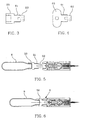
- a piercing apparatus according to the invention is shown as a whole in Figs. 1 and 2 in a wait condition and in an operated state, respectively.
- such a piercing apparatus can be employed in a self-emptying bag 100, which is depicted by dotted lines in a closed condition (Fig. 7) and in a following consequently opened condition (Fig. 8).
- the bag 100 is endowed with a shoulder-strap 200.
- the bag 100 is provided with a folding cover 101.
- closure means of the folding cover 101 that is diagrammatically shown in 300, it can be of any suitable kind, such as press-stud, Velcro (trade name) or the like, provided that it is yielding under the action of an ejection device, using the piercing apparatus according to the invention, in order to allow the bag to be opened and its contents to fall down.
- the bag 100 is lined inside by a lining 400 shaped as a pocket that is preferably held, although this is not shown in the drawing, in its upper hem by the edge of the bag in a removable way, e.g. by means of a zip or so called Velcro.
- a lining 400 shaped as a pocket that is preferably held, although this is not shown in the drawing, in its upper hem by the edge of the bag in a removable way, e.g. by means of a zip or so called Velcro.
- the bottle piercing apparatus according to the invention is located in the space 401.
- the airtight expandable sack 1 as diagrammatically depicted in its collapsed state in Fig. 7, is arranged in a collected way, e.g. folded, under the lining 400.
- Fig. 8 the expandable sack l'takes on the form of a prismatic body, so to be able to keep the lining 400 overturned in 400' as shown in the same figures.
- connection duct 10 At the bottom the expandable sack 1 is hermetically connected through connection duct 10 to an elongated housing 20 of a compressed gas feeder 2.
- the elongated housing 20 can be made of a suitable plastic material.
- the compressed gas feeder 2 is located below the expandable sack 1, being preferably arranged between restraint panels 5 e.g. of a suitable foamy plastic material, in order to prevent the compressed gas 2 from wandering troublesomely on the base 102 of the bag.
- Fig.1 which is a longitudinal section view of the compressed gas feeder 2, the generally cylindrical, elongated housing 20 thereof, whose inner chamber 21 is in communication with the expandable sack 1, frontally carries a small bottle 6 of compressed air or other gas and, in a sequence from an end to the other end thereof, a spring-charged piercing element 7 and a release mechanism 8.
- the small gas bottle 6 having a pierceable sealed mouth 60, is screwed to the elongated housing 20 by means of its externally threaded neck 61.
- the small gas bottle has such a capacity that the expandable sack 1, after being inflated instantaneously, is able with its expansion to exert a sufficient force to expel objects contained inside the bag 100 between the lining 400 and the bag cover 101 upon the opening of the closure means and the overturning of the cover.
- the gas bottle 6 is closed in its mouth 60 by a septum that is easily pierceable by the piercing element 7 provided with a piercing bit 72.
- the piercing bit 72 preferably as a mouthpiece of a flute, is shaped so that the cut portion of septum remains in part laterally attached to the septum, without obstructing the emission of gas.
- the piercing bit 72 has an axial passageway 73.
- the release mechanism 8, which pushes the piercing element 7 against the gas bottle 6, comprises a release member being connected to a flexible transmission 30 of control means 3, e.g. the control means of a self-emptying bag in Figs. 7 and 8.
- such a release member is a protuberance 87, that is slidable in the inner chamber 21 of the elongated housing 20 by the operation of the flexible transmission 30 against a counteracting spring 89.
- the protuberance 87 is rigidly connected to a cylindrical element 83 that is provided with at least a pair of opposed tooth 84. These tooth 84 are designed to slide on grooves 85 that are provided in the inner chamber 21 of the elongated housing 20.
- the piercing element 7 is fixed to one end of a collet chuck 70, which, at the other end, is provided with fingers 88 to grip the protuberance 87 of the release mechanism 8.
- the collet chuck 70 is very similar to that one of a propelling pencil and can be made of plastic material.
- the collet chuck 70 being movable between a gripping condition (Fig. 1) and a releasing condition of the protuberance 87 (Fig. 2), is slidable coaxially with respect to an external cam profile 90 surrounding at least the fingers 88 under the action of a spiral spring 91.
- the spiral spring 91 is abutted between a flange 92 of the front end of the collet chuck 70 and the external cam profile 90.
- the external cam profile 90 that is in abutment against an internal circumferential projection 93 of the inner chamber 21 of the elongated housing 20, has an internal space 94, that is preferably cylindrical, with a consecutive frusto-conical portion 95. Then, such an internal space is adapted to receive and retain the fingers 88 of the collet chuck 70 in engagement with the protuberance 87 against the slide of the same collet chuck 70.
- the control means 3 which is generally a Bowden cable
- its flexible transmission 30 being connected to the protuberance 87
- the protuberance 87 slides, by virtue of its tooth 84 engaging the grooves 85 of the inner chamber 21 of the elongated housing 20 against the action of the counteracting spring 89.
- the protuberance 87 loses the engagement with the fingers 88 of the collet chuck 70.
- the fingers for example four in number, being retained no longer by the protuberance 87 against the cylindrical-frustoconical space 94-95 of the cam profile 90, are able to pass through the cylindrical portion 94 of said space 94-95.
- the collet chuck 70 that is pushed by the spring 91 in abutment between the flange 92 of the same collet chuck 70 and the cam profile 90, is obliged to travel suddenly toward the front end of the elongated housing 20, where the small gas bottle 6 is screwed.
- the expandable sack 1 is inflated immediately.
- a seal gasket 99 being situated around the connection with the flexible transmission 30 of the release element, is provided.
- the reloading tool has an elongated cylindrical body, including a maximum diameter, first section 50, an intermediate diameter, second section 51, and a minimum diameter, third section 52.
- the maximum diameter, first section 50 is internally hollow and is provided with an internal thread for screwing onto the threaded neck of the gas bottle 6.
- the second section 51 that is externally threaded, has a diameter equal to that of the neck of the gas bottle 6 with same thread.
- the minimum diameter, internally hollow, third section 52 is such that it surrounds the piercing element 7.
- the section 52 of the tool causes the collet chock 70 to move backward until the fingers 88 of the collet chock 70 engage the protuberance 87 of the release element. This engagement is made temporarily firm by the cam profile 90, against which the fingers 88 are retained, until the operation of the control means 3.
- a second embodiment of the tool for reloading the piercing apparatus is shown.
- This second embodiment is characterized by a shaped body 53 comprising an externally threaded section 51 being equal to that one of the neck of the small bottle and a hollow end portion 52 such that it surrounds the piercing element 7 and cause it to move backward until the fingers of the collet chock 70 engage the protuberance 87 of the release element, as described with reference to the first embodiment of tool.
- the shaped body 53 acts as a handle.
- the reloading tool can be screwed and instead of it a new charged small bottle 6 can be located.
- a sea rescue device is diagrammatically shown.
- a compressed gas feeder 2 is located side to side to a rolled up expandable sack 1, as shown in Fig. 11.
- the container 104 has a slidable cover 105 with a handle 106.
- a free end of control means is connected to the slidable cover 104.
Landscapes
- Containers And Packaging Bodies Having A Special Means To Remove Contents (AREA)
- Devices For Opening Bottles Or Cans (AREA)
- Perforating, Stamping-Out Or Severing By Means Other Than Cutting (AREA)
- Fats And Perfumes (AREA)
- Air Bags (AREA)
- Filling Or Discharging Of Gas Storage Vessels (AREA)
- Vacuum Packaging (AREA)
- Manipulator (AREA)
Claims (6)
- Un dispositif de perforation pour percer une petite bouteille de gaz comprimé pour gonfler rapidement une poche, comprenant:- une poche gonflable (1) disposée sur la base (102 ; 103) d'un récipient (100 ; 104)- un distributeur de gaz comprimé (2) situé sous la poche gonflable (1), comprenant :caractérisée par le fait que:une petite bouteille de gaz comprimé (6) à ouverture perforable (60) dont le colest extérieurement fileté (61),un boîtier (20) relié à la petite bouteille de gaz comprimé (6) et à la poche gonflable (1), et dans un compartiment interne (21) du boîtier un élément de perforation (7) comprenant un foret (72) muni d'un passage axial (73) communiquant avec la poche gonflable (1).Un mécanisme de détente (8), chargé par un ressort de force opposée (89) pour pousser l'élément de perforation (7) contre la petite bouteille de gaz comprimé (6), comprenant un élément de détente relié à une transmission flexible (30) d'un dispositif de contrôle (3) ;- l'élément de détente est une protubérance (87) et est introduit par glissement dans le compartiment interne (21) du boîtier allongé (20) sous l'action exercée sur la transmission flexible (30) contre le ressort de force opposée (89) ; et- l'élément de perforation (7) est fixé à l'extrémité antérieure d'un mandrin à collet (70) qui, en tant que tel, est fourni à son extrémité arrière, de griffes (88) pour bloquer cette protubérance (87) de l'élément de détente ; le mandrin à collet (70) peut passer d'une condition de serrage à une condition de détente de la protubérance (87) selon l'action du dispositif de contrôle.
- Le dispositif de perforation, selon la revendication 1, caractérisé par le fait que le mandrin à collet (70) peut glisser en direction coaxiale par rapport à un profil de came extérieure (90) entourant au moins les griffes (88) sous l'action d'un ressort à spirale (91) appuyé entre une bride (92) de l'extrémité antérieure du mandrin à collet (70) et le profil de came extérieure (90) ; le profil de came extérieure (90), qui est en appui contre une projection circonférentielle interne (93) du compartiment interne (21) du boîtier allongé (20), ayant un espace interne adapté pour recevoir et retenir les griffes (88) du mandrin à collet (70) engagées sur la protubérance (87) contre le chariot du mandrin à collet (70).
- Le dispositif de perforation selon la revendication 1, caractérisé par le fait qu'une partie du boîtier allongé (20) près du raccord avec la bouteille de gaz (6) est vissée à la partie restante du boîtier allongé (20).
- Le dispositif de perforation selon la revendication 1, caractérisé par le fait qu'un joint d'étanchéité est situé autour du raccord à la transmission flexible (30) de l'élément de détente.
- Un outil pour recharger le dispositif de perforation selon la revendication 1, caractérisé par le fait que cet outil de rechargement a un corps cylindrique allongé ; le diamètre maximum de la première section (50) est creux et est muni d'un filetage interne pour se visser sur le col fileté d'une bouteille de gaz (6) ; la deuxième section (51), filetée extérieurement, a un diamètre égal à celui du col de la bouteille de gaz (6), et le diamètre minimum de la troisième section (52) est creux, pour entourer l'élément de perforation (7) et pousser le mandrin à collet (70) à reculer jusqu'à ce que les griffes (88) du mandrin à collet (70) s'engagent sur la protubérance (87) de l'élément de détente.
- Un outil pour recharger le dispositif de perforation selon la revendication 1, caractérisé par le fait que cet outil a un corps moulé (53) comprenant une section filetée extérieurement (51) égale à celle du col de la petite bouteille et une partie terminale creuse (52) pour entourer l'élément de perforation (7) et le pousser à reculer jusqu'à ce que les griffes du mandrin à collet (70) s'engagent sur la protubérance (87).
Applications Claiming Priority (2)
| Application Number | Priority Date | Filing Date | Title |
|---|---|---|---|
| ITRM20030473 | 2003-10-15 | ||
| IT000473A ITRM20030473A1 (it) | 2003-10-15 | 2003-10-15 | Dispositivo di perforazione di una bomboletta di gas |
Publications (2)
| Publication Number | Publication Date |
|---|---|
| EP1523902A1 EP1523902A1 (fr) | 2005-04-20 |
| EP1523902B1 true EP1523902B1 (fr) | 2006-12-13 |
Family
ID=30131615
Family Applications (1)
| Application Number | Title | Priority Date | Filing Date |
|---|---|---|---|
| EP04425766A Expired - Lifetime EP1523902B1 (fr) | 2003-10-15 | 2004-10-12 | Dispositif de perçage d'une petite bouteille de gaz sous pression pour le gonflage rapide d'un sac et outil de recharge dudit dispositif |
Country Status (6)
| Country | Link |
|---|---|
| US (1) | US6991005B2 (fr) |
| EP (1) | EP1523902B1 (fr) |
| JP (1) | JP2005119748A (fr) |
| AT (1) | ATE347826T1 (fr) |
| DE (1) | DE602004003655D1 (fr) |
| IT (1) | ITRM20030473A1 (fr) |
Families Citing this family (12)
| Publication number | Priority date | Publication date | Assignee | Title |
|---|---|---|---|---|
| US7669616B2 (en) * | 2006-12-20 | 2010-03-02 | Ultra Electronics Ocean Systems, Inc. | Apparatus for puncturing a gas filled bottle |
| US20090246085A1 (en) * | 2008-03-31 | 2009-10-01 | Helicos Biosciences Corporation | Liquid Handling System and Methods for Mixing and Delivering Liquid Reagents |
| FR2976269B1 (fr) * | 2011-06-08 | 2013-06-28 | Rexam Dispensing Sys | Flacon de distribution d'un produit fluide |
| WO2014018332A1 (fr) * | 2012-07-23 | 2014-01-30 | Carleton Technologies, Inc. | Ensemble gonfleur conçu pour un gonflement manuel ou automatique |
| EP2926869B1 (fr) * | 2013-12-13 | 2018-07-18 | Ortovox Sportartikel GmbH | Système de coussin gonflable destiné à la protection de personnes |
| US9821183B2 (en) | 2014-07-11 | 2017-11-21 | Kidde Technologies, Inc. | Motorized actuator for a fire extinguisher |
| US9539452B2 (en) * | 2014-07-11 | 2017-01-10 | Kidde Technologies, Inc. | Rapid pressure diffusion actuator for a fire extinguisher |
| US9649520B2 (en) | 2014-07-11 | 2017-05-16 | Kidde Technologies, Inc. | Burst disc puncture pressure-imbalance actuator for a fire extinguisher |
| CN104290128B (zh) * | 2014-09-24 | 2016-05-04 | 福州大学 | 一种连杆驱动的纸花盆打孔机及其使用方法 |
| US9861846B2 (en) * | 2015-01-22 | 2018-01-09 | Kidde Technologies, Inc. | Spring-collet mechanism for activating a fire extinguisher |
| CN111322907B (zh) * | 2020-03-05 | 2022-04-29 | 观典防务技术股份有限公司 | 一种纯机械结构方式扎破电击弹中的动力氮气气瓶 |
| CN119175143B (zh) * | 2024-11-22 | 2025-02-14 | 寿光市中瑞生物科技股份有限公司 | 一种山梨醇颗粒研磨机 |
Family Cites Families (5)
| Publication number | Priority date | Publication date | Assignee | Title |
|---|---|---|---|---|
| US5458164A (en) * | 1993-08-24 | 1995-10-17 | La Rue International Inc. | Luggage stuffer |
| US5601124A (en) * | 1995-02-07 | 1997-02-11 | Halkey-Roberts Corporation | Autoinflator with apertured housing |
| ATE220302T1 (de) * | 1997-09-30 | 2002-07-15 | Benedetto Fedeli | Selbstentleerende tasche |
| IT1307293B1 (it) * | 1999-12-16 | 2001-10-30 | Benedetto Fedeli | Dispositivo di espulsione degli oggetti contenuti all'interno di unaborsa nell'evenienza di uno scippo. |
| US6705488B2 (en) * | 2001-09-07 | 2004-03-16 | Halkey-Roberts Corporation | Bobbin for automatic inflator |
-
2003
- 2003-10-15 IT IT000473A patent/ITRM20030473A1/it unknown
-
2004
- 2004-10-12 EP EP04425766A patent/EP1523902B1/fr not_active Expired - Lifetime
- 2004-10-12 DE DE602004003655T patent/DE602004003655D1/de not_active Expired - Lifetime
- 2004-10-12 AT AT04425766T patent/ATE347826T1/de not_active IP Right Cessation
- 2004-10-13 US US10/962,543 patent/US6991005B2/en not_active Expired - Fee Related
- 2004-10-14 JP JP2004300296A patent/JP2005119748A/ja active Pending
Also Published As
| Publication number | Publication date |
|---|---|
| ITRM20030473A1 (it) | 2005-04-16 |
| ATE347826T1 (de) | 2007-01-15 |
| EP1523902A1 (fr) | 2005-04-20 |
| US20050081947A1 (en) | 2005-04-21 |
| JP2005119748A (ja) | 2005-05-12 |
| US6991005B2 (en) | 2006-01-31 |
| ITRM20030473A0 (it) | 2003-10-15 |
| DE602004003655D1 (de) | 2007-01-25 |
Similar Documents
| Publication | Publication Date | Title |
|---|---|---|
| EP1523902B1 (fr) | Dispositif de perçage d'une petite bouteille de gaz sous pression pour le gonflage rapide d'un sac et outil de recharge dudit dispositif | |
| US5301631A (en) | Balloon emergency locating device | |
| US4562837A (en) | Air escape filter apparatus | |
| EP0119333B1 (fr) | Article flottant gonflable emballé sous vide | |
| US6793429B2 (en) | Chalk holding device | |
| US8469015B2 (en) | Low cost rescue launcher system | |
| US6247471B1 (en) | Smoke hood with oxygen supply device and method of use | |
| US4498604A (en) | Automatic inflator | |
| US5884362A (en) | Expandable handle of luggage | |
| US3689105A (en) | Inflatable vehicular safety device | |
| US3437245A (en) | Powder dispenser | |
| EP1110475B1 (fr) | Appareil d'éjection pour éjecter les objets d'un sac en cas de vol | |
| US6373384B1 (en) | Inflatable security device | |
| US6168046B1 (en) | Vitamin and pill dispensing device | |
| US5813581A (en) | Pouch for truncheon | |
| US20040123793A1 (en) | Man overboard locator device | |
| US4803745A (en) | Survival knife sheath | |
| US4805533A (en) | Swimmer pyrotechnic signal device | |
| US7300206B2 (en) | Self-emptying bag having a quick coupling buckle assembly, in particular for shoulder-strap | |
| NZ206888A (en) | Device for firing signal cartridges | |
| US3289827A (en) | Container for use in space ships | |
| US20230068361A1 (en) | Shock tube coil system | |
| JPH0631351Y2 (ja) | 筒形クラッカー | |
| JPH0631355Y2 (ja) | プッシュ式クラッカー | |
| US3302819A (en) | Delayed opening package |
Legal Events
| Date | Code | Title | Description |
|---|---|---|---|
| PUAI | Public reference made under article 153(3) epc to a published international application that has entered the european phase |
Free format text: ORIGINAL CODE: 0009012 |
|
| AK | Designated contracting states |
Kind code of ref document: A1 Designated state(s): AT BE BG CH CY CZ DE DK EE ES FI FR GB GR HU IE IT LI LU MC NL PL PT RO SE SI SK TR |
|
| AX | Request for extension of the european patent |
Extension state: AL HR LT LV MK |
|
| 17P | Request for examination filed |
Effective date: 20051017 |
|
| AKX | Designation fees paid |
Designated state(s): AT BE BG CH CY CZ DE DK EE ES FI FR GB GR HU IE IT LI LU MC NL PL PT RO SE SI SK TR |
|
| GRAP | Despatch of communication of intention to grant a patent |
Free format text: ORIGINAL CODE: EPIDOSNIGR1 |
|
| GRAS | Grant fee paid |
Free format text: ORIGINAL CODE: EPIDOSNIGR3 |
|
| GRAA | (expected) grant |
Free format text: ORIGINAL CODE: 0009210 |
|
| AK | Designated contracting states |
Kind code of ref document: B1 Designated state(s): AT BE BG CH CY CZ DE DK EE ES FI FR GB GR HU IE IT LI LU MC NL PL PT RO SE SI SK TR |
|
| PG25 | Lapsed in a contracting state [announced via postgrant information from national office to epo] |
Ref country code: IT Free format text: LAPSE BECAUSE OF FAILURE TO SUBMIT A TRANSLATION OF THE DESCRIPTION OR TO PAY THE FEE WITHIN THE PRESCRIBED TIME-LIMIT;WARNING: LAPSES OF ITALIAN PATENTS WITH EFFECTIVE DATE BEFORE 2007 MAY HAVE OCCURRED AT ANY TIME BEFORE 2007. THE CORRECT EFFECTIVE DATE MAY BE DIFFERENT FROM THE ONE RECORDED. Effective date: 20061213 Ref country code: NL Free format text: LAPSE BECAUSE OF FAILURE TO SUBMIT A TRANSLATION OF THE DESCRIPTION OR TO PAY THE FEE WITHIN THE PRESCRIBED TIME-LIMIT Effective date: 20061213 Ref country code: SI Free format text: LAPSE BECAUSE OF FAILURE TO SUBMIT A TRANSLATION OF THE DESCRIPTION OR TO PAY THE FEE WITHIN THE PRESCRIBED TIME-LIMIT Effective date: 20061213 Ref country code: FI Free format text: LAPSE BECAUSE OF FAILURE TO SUBMIT A TRANSLATION OF THE DESCRIPTION OR TO PAY THE FEE WITHIN THE PRESCRIBED TIME-LIMIT Effective date: 20061213 Ref country code: RO Free format text: LAPSE BECAUSE OF FAILURE TO SUBMIT A TRANSLATION OF THE DESCRIPTION OR TO PAY THE FEE WITHIN THE PRESCRIBED TIME-LIMIT Effective date: 20061213 Ref country code: LI Free format text: LAPSE BECAUSE OF FAILURE TO SUBMIT A TRANSLATION OF THE DESCRIPTION OR TO PAY THE FEE WITHIN THE PRESCRIBED TIME-LIMIT Effective date: 20061213 Ref country code: CH Free format text: LAPSE BECAUSE OF FAILURE TO SUBMIT A TRANSLATION OF THE DESCRIPTION OR TO PAY THE FEE WITHIN THE PRESCRIBED TIME-LIMIT Effective date: 20061213 Ref country code: BE Free format text: LAPSE BECAUSE OF FAILURE TO SUBMIT A TRANSLATION OF THE DESCRIPTION OR TO PAY THE FEE WITHIN THE PRESCRIBED TIME-LIMIT Effective date: 20061213 Ref country code: AT Free format text: LAPSE BECAUSE OF FAILURE TO SUBMIT A TRANSLATION OF THE DESCRIPTION OR TO PAY THE FEE WITHIN THE PRESCRIBED TIME-LIMIT Effective date: 20061213 Ref country code: DK Free format text: LAPSE BECAUSE OF FAILURE TO SUBMIT A TRANSLATION OF THE DESCRIPTION OR TO PAY THE FEE WITHIN THE PRESCRIBED TIME-LIMIT Effective date: 20061213 Ref country code: PL Free format text: LAPSE BECAUSE OF FAILURE TO SUBMIT A TRANSLATION OF THE DESCRIPTION OR TO PAY THE FEE WITHIN THE PRESCRIBED TIME-LIMIT Effective date: 20061213 Ref country code: SK Free format text: LAPSE BECAUSE OF FAILURE TO SUBMIT A TRANSLATION OF THE DESCRIPTION OR TO PAY THE FEE WITHIN THE PRESCRIBED TIME-LIMIT Effective date: 20061213 Ref country code: CZ Free format text: LAPSE BECAUSE OF FAILURE TO SUBMIT A TRANSLATION OF THE DESCRIPTION OR TO PAY THE FEE WITHIN THE PRESCRIBED TIME-LIMIT Effective date: 20061213 |
|
| REG | Reference to a national code |
Ref country code: GB Ref legal event code: FG4D |
|
| REG | Reference to a national code |
Ref country code: CH Ref legal event code: EP |
|
| REG | Reference to a national code |
Ref country code: IE Ref legal event code: FG4D |
|
| REF | Corresponds to: |
Ref document number: 602004003655 Country of ref document: DE Date of ref document: 20070125 Kind code of ref document: P |
|
| PG25 | Lapsed in a contracting state [announced via postgrant information from national office to epo] |
Ref country code: BG Free format text: LAPSE BECAUSE OF FAILURE TO SUBMIT A TRANSLATION OF THE DESCRIPTION OR TO PAY THE FEE WITHIN THE PRESCRIBED TIME-LIMIT Effective date: 20070313 Ref country code: SE Free format text: LAPSE BECAUSE OF FAILURE TO SUBMIT A TRANSLATION OF THE DESCRIPTION OR TO PAY THE FEE WITHIN THE PRESCRIBED TIME-LIMIT Effective date: 20070313 |
|
| PG25 | Lapsed in a contracting state [announced via postgrant information from national office to epo] |
Ref country code: DE Free format text: LAPSE BECAUSE OF FAILURE TO SUBMIT A TRANSLATION OF THE DESCRIPTION OR TO PAY THE FEE WITHIN THE PRESCRIBED TIME-LIMIT Effective date: 20070314 |
|
| PG25 | Lapsed in a contracting state [announced via postgrant information from national office to epo] |
Ref country code: ES Free format text: LAPSE BECAUSE OF FAILURE TO SUBMIT A TRANSLATION OF THE DESCRIPTION OR TO PAY THE FEE WITHIN THE PRESCRIBED TIME-LIMIT Effective date: 20070324 |
|
| PG25 | Lapsed in a contracting state [announced via postgrant information from national office to epo] |
Ref country code: PT Free format text: LAPSE BECAUSE OF FAILURE TO SUBMIT A TRANSLATION OF THE DESCRIPTION OR TO PAY THE FEE WITHIN THE PRESCRIBED TIME-LIMIT Effective date: 20070514 |
|
| NLV1 | Nl: lapsed or annulled due to failure to fulfill the requirements of art. 29p and 29m of the patents act | ||
| REG | Reference to a national code |
Ref country code: CH Ref legal event code: PL |
|
| EN | Fr: translation not filed | ||
| PLBE | No opposition filed within time limit |
Free format text: ORIGINAL CODE: 0009261 |
|
| STAA | Information on the status of an ep patent application or granted ep patent |
Free format text: STATUS: NO OPPOSITION FILED WITHIN TIME LIMIT |
|
| 26N | No opposition filed |
Effective date: 20070914 |
|
| PG25 | Lapsed in a contracting state [announced via postgrant information from national office to epo] |
Ref country code: GR Free format text: LAPSE BECAUSE OF FAILURE TO SUBMIT A TRANSLATION OF THE DESCRIPTION OR TO PAY THE FEE WITHIN THE PRESCRIBED TIME-LIMIT Effective date: 20070314 Ref country code: FR Free format text: LAPSE BECAUSE OF FAILURE TO SUBMIT A TRANSLATION OF THE DESCRIPTION OR TO PAY THE FEE WITHIN THE PRESCRIBED TIME-LIMIT Effective date: 20070803 |
|
| PG25 | Lapsed in a contracting state [announced via postgrant information from national office to epo] |
Ref country code: MC Free format text: LAPSE BECAUSE OF NON-PAYMENT OF DUE FEES Effective date: 20071031 |
|
| PG25 | Lapsed in a contracting state [announced via postgrant information from national office to epo] |
Ref country code: IE Free format text: LAPSE BECAUSE OF NON-PAYMENT OF DUE FEES Effective date: 20071012 |
|
| PG25 | Lapsed in a contracting state [announced via postgrant information from national office to epo] |
Ref country code: FR Free format text: LAPSE BECAUSE OF FAILURE TO SUBMIT A TRANSLATION OF THE DESCRIPTION OR TO PAY THE FEE WITHIN THE PRESCRIBED TIME-LIMIT Effective date: 20061213 |
|
| PG25 | Lapsed in a contracting state [announced via postgrant information from national office to epo] |
Ref country code: EE Free format text: LAPSE BECAUSE OF FAILURE TO SUBMIT A TRANSLATION OF THE DESCRIPTION OR TO PAY THE FEE WITHIN THE PRESCRIBED TIME-LIMIT Effective date: 20061213 |
|
| GBPC | Gb: european patent ceased through non-payment of renewal fee |
Effective date: 20081012 |
|
| PG25 | Lapsed in a contracting state [announced via postgrant information from national office to epo] |
Ref country code: LU Free format text: LAPSE BECAUSE OF NON-PAYMENT OF DUE FEES Effective date: 20071012 Ref country code: CY Free format text: LAPSE BECAUSE OF FAILURE TO SUBMIT A TRANSLATION OF THE DESCRIPTION OR TO PAY THE FEE WITHIN THE PRESCRIBED TIME-LIMIT Effective date: 20061213 |
|
| PG25 | Lapsed in a contracting state [announced via postgrant information from national office to epo] |
Ref country code: TR Free format text: LAPSE BECAUSE OF FAILURE TO SUBMIT A TRANSLATION OF THE DESCRIPTION OR TO PAY THE FEE WITHIN THE PRESCRIBED TIME-LIMIT Effective date: 20061213 Ref country code: HU Free format text: LAPSE BECAUSE OF FAILURE TO SUBMIT A TRANSLATION OF THE DESCRIPTION OR TO PAY THE FEE WITHIN THE PRESCRIBED TIME-LIMIT Effective date: 20070614 |
|
| PG25 | Lapsed in a contracting state [announced via postgrant information from national office to epo] |
Ref country code: GB Free format text: LAPSE BECAUSE OF NON-PAYMENT OF DUE FEES Effective date: 20081012 |