EP1523900B1 - Top end stop of linear slide fastener - Google Patents
Top end stop of linear slide fastener Download PDFInfo
- Publication number
- EP1523900B1 EP1523900B1 EP04022950A EP04022950A EP1523900B1 EP 1523900 B1 EP1523900 B1 EP 1523900B1 EP 04022950 A EP04022950 A EP 04022950A EP 04022950 A EP04022950 A EP 04022950A EP 1523900 B1 EP1523900 B1 EP 1523900B1
- Authority
- EP
- European Patent Office
- Prior art keywords
- fastener
- linear
- elements
- top end
- tape
- Prior art date
- Legal status (The legal status is an assumption and is not a legal conclusion. Google has not performed a legal analysis and makes no representation as to the accuracy of the status listed.)
- Expired - Lifetime
Links
Images


Classifications
-
- A—HUMAN NECESSITIES
- A44—HABERDASHERY; JEWELLERY
- A44B—BUTTONS, PINS, BUCKLES, SLIDE FASTENERS, OR THE LIKE
- A44B19/00—Slide fasteners
- A44B19/24—Details
- A44B19/36—Means for permanently uniting the stringers at the end; Means for stopping movement of slider at the end
-
- A—HUMAN NECESSITIES
- A44—HABERDASHERY; JEWELLERY
- A44B—BUTTONS, PINS, BUCKLES, SLIDE FASTENERS, OR THE LIKE
- A44B19/00—Slide fasteners
- A44B19/24—Details
- A44B19/38—Means at the end of stringer by which the slider can be freed from one stringer, e.g. stringers can be completely separated from each other
- A44B19/384—Separable slide fasteners with quick opening devices
- A44B19/386—Top end stop means for quick opening slide fasteners
-
- Y—GENERAL TAGGING OF NEW TECHNOLOGICAL DEVELOPMENTS; GENERAL TAGGING OF CROSS-SECTIONAL TECHNOLOGIES SPANNING OVER SEVERAL SECTIONS OF THE IPC; TECHNICAL SUBJECTS COVERED BY FORMER USPC CROSS-REFERENCE ART COLLECTIONS [XRACs] AND DIGESTS
- Y10—TECHNICAL SUBJECTS COVERED BY FORMER USPC
- Y10T—TECHNICAL SUBJECTS COVERED BY FORMER US CLASSIFICATION
- Y10T24/00—Buckles, buttons, clasps, etc.
- Y10T24/25—Zipper or required component thereof
- Y10T24/2502—Plural zippers
-
- Y—GENERAL TAGGING OF NEW TECHNOLOGICAL DEVELOPMENTS; GENERAL TAGGING OF CROSS-SECTIONAL TECHNOLOGIES SPANNING OVER SEVERAL SECTIONS OF THE IPC; TECHNICAL SUBJECTS COVERED BY FORMER USPC CROSS-REFERENCE ART COLLECTIONS [XRACs] AND DIGESTS
- Y10—TECHNICAL SUBJECTS COVERED BY FORMER USPC
- Y10T—TECHNICAL SUBJECTS COVERED BY FORMER US CLASSIFICATION
- Y10T24/00—Buckles, buttons, clasps, etc.
- Y10T24/25—Zipper or required component thereof
- Y10T24/2514—Zipper or required component thereof with distinct member for sealing surfaces
-
- Y—GENERAL TAGGING OF NEW TECHNOLOGICAL DEVELOPMENTS; GENERAL TAGGING OF CROSS-SECTIONAL TECHNOLOGIES SPANNING OVER SEVERAL SECTIONS OF THE IPC; TECHNICAL SUBJECTS COVERED BY FORMER USPC CROSS-REFERENCE ART COLLECTIONS [XRACs] AND DIGESTS
- Y10—TECHNICAL SUBJECTS COVERED BY FORMER USPC
- Y10T—TECHNICAL SUBJECTS COVERED BY FORMER US CLASSIFICATION
- Y10T24/00—Buckles, buttons, clasps, etc.
- Y10T24/25—Zipper or required component thereof
- Y10T24/2518—Zipper or required component thereof having coiled or bent continuous wire interlocking surface
- Y10T24/252—Zipper or required component thereof having coiled or bent continuous wire interlocking surface with stringer tape interwoven or knitted therewith
-
- Y—GENERAL TAGGING OF NEW TECHNOLOGICAL DEVELOPMENTS; GENERAL TAGGING OF CROSS-SECTIONAL TECHNOLOGIES SPANNING OVER SEVERAL SECTIONS OF THE IPC; TECHNICAL SUBJECTS COVERED BY FORMER USPC CROSS-REFERENCE ART COLLECTIONS [XRACs] AND DIGESTS
- Y10—TECHNICAL SUBJECTS COVERED BY FORMER USPC
- Y10T—TECHNICAL SUBJECTS COVERED BY FORMER US CLASSIFICATION
- Y10T24/00—Buckles, buttons, clasps, etc.
- Y10T24/25—Zipper or required component thereof
- Y10T24/2593—Zipper or required component thereof including complementary, aligning means attached to ends of interlocking surfaces
-
- Y—GENERAL TAGGING OF NEW TECHNOLOGICAL DEVELOPMENTS; GENERAL TAGGING OF CROSS-SECTIONAL TECHNOLOGIES SPANNING OVER SEVERAL SECTIONS OF THE IPC; TECHNICAL SUBJECTS COVERED BY FORMER USPC CROSS-REFERENCE ART COLLECTIONS [XRACs] AND DIGESTS
- Y10—TECHNICAL SUBJECTS COVERED BY FORMER USPC
- Y10T—TECHNICAL SUBJECTS COVERED BY FORMER US CLASSIFICATION
- Y10T24/00—Buckles, buttons, clasps, etc.
- Y10T24/25—Zipper or required component thereof
- Y10T24/2598—Zipper or required component thereof including means for obstructing movement of slider
Definitions
- the present invention relates to a linear slide fastener with a top end stop in which linear fastener element rows formed of synthetic fiber mono-filaments are mounted on side edges of a fastener tape, the top end stop being formed at a top end portion of the fastener tape by processing the linear fastener elements.
- the fastener tape 112 the core thread 116, the sewing thread and the like are fused together integrally and expanded widely to both sides with respect to the coupling heads 119 and inverted portions 120 of connected other fastener elements so as to form a top end stop 101 of the linear slide fastener.
- GB-A- 1 000 597 discloses a sliding clasp fastener of the meander type in which top and bottom end stops consist of straight pins inserted into the longitudinal channel formed by the fastener elements.
- US-A-3 972 095 discloses a sliding clasp fastener of the concealed type having an end stop made of plastic material fused with the fastener elements.
- the fused material forms an arcuately shaped prong extending on the base side of the fastener elements for engagement with a slider.
- the present invention has been accomplished in views of the above-described problems and a primary object of the present invention is to provide a normal type or hidden type linear slide fastener with a top end stop which has a plasticity without becoming rigid and is free of any burr on its surface, thereby ensuring an excellent tactile feeling, this slide fastener being capable of being produced at a low cost with simple manufacturing means.
- another object of the present invention is to provide a normal type or hidden type linear slide fastener with a top end stop in which right and left coupling heads in the top end stop formed by fusing the linear fastener elements with the fastener tape are in a non-coupling condition while end faces of the inverted portions make contact with an inside wall face of a flange in a slider so as to stop the slider from sliding.
- Still another object of the present invention is to provide a normal type or hidden type linear slide fastener with a top end stop in which right and left coupling heads in the top end stop formed by fusing the linear fastener elements with the fastener tape are in a non-coupling condition while the inverted portions make contact with the front end of a flange of a slider so as to stop the slider from sliding.
- Yet still another object of the present invention is to provide a normal type linear slide fastener with a top end stop in which coil-like fastener elements or zigzag-like fastener elements are employed as the fastener elements in a normal type slide fastener, the top end stop being produced easily with this fastener element.
- a further object of the present invention is to provide a hidden type linear slide fastener with a top end stop in which coil-like fastener elements are used as the fastener elements in the hidden type slide fastener, the top end stop being produced easily with this fastener element.
- a still further object of the present invention is to provide a good quality normal type or hidden type linear slide fastener with a top end stop in which, when the top end stop is manufactured with the linear fastener elements, a core thread is passed through coil-like fastener elements or zigzag-like fastener elements, thereby preventing the linear fastener elements from escaping from the sewing threads at the time of processing.
- a still further object of the present invention is to provide a linear slide fastener with a top end stop which is formed using the linear fastener elements and can be fixed easily and securely on a fastener tape in case of both the normal type and hidden type linear slide fasteners, the top end stop being formed strictly and stably.
- a still further object of the present invention is to provide a linear slide fastener with a top end stop which is manufactured using upper and lower leg portions projecting to the side of the sewing threads in the coil-like fastener elements or the zigzag-like fastener elements, the top end stop being formed with a high strength.
- the invention provides a linear slide fastener, with a top end stop, the linear slide fastener having a linear fastener element row attached to a side edge of a fastener tape or a bent side edge bent in parallel along the side edge.
- the linear fastener element row comprises a plurality of linear fastener elements, at least one linear fastener element of the linear fastener elements at a top end portion of the linear fastener element row has been moved to an inside of the fastener tape more inwardly compared to the position of the other linear fastener elements, and the moved linear fastener element and the fastener tape have been fused together and fixed so as to form the top end stop.
- the linear fastener elements comprise a coupling head and an inverted portion connecting adjacent linear fastener elements each other, the inverted portion of the moved linear fastener element is projected to the inside of the fastener tape more inwardly compared to a position of the inverted portions of the other linear fastener elements.
- At least one linear fastener element of the linear fastener elements at a top end portion of the linear fastener element row attached to the side edge of the fastener tape is moved to an inside of the fastener tape more inwardly compared to a position of the other linear fastener elements without addition of any other material, and the fastener elements and the fastener tape are fused together so as to produce a top end stop. Consequently, this produced top end stop has a plastic surface and ensures an excellent quality without any burr, and further can be produced at a low cost with simple means.
- the linear fastener element which is moved, fused together and fixed on the fastener tape makes contact with a slider so as to stop the slider.
- the linear fastener element fused together and fixed on the fastener tape has a stop mechanism in which while the right and left coupling heads oppose each other in a non-coupling condition, an inverted portion makes contact with an inside wall face of a flange of the slider.
- the inverted portions on the opposite side to the coupling heads of the right and left fastener elements retreat further to the inside of the fastener tape and project so that they make contact with the inside face of the flange, thereby stopping the slider from sliding. Consequently, with such a simple structure, the slider can be stopped with a smart appearance.
- the linear fastener element at a portion where the linear fastener element and the fastener tape are fused together and fixed has a stop mechanism in which while the right and left coupling heads oppose each other in a non-coupling condition, an inverted portion makes contact with a front end portion of a flange.
- the stop mechanism in which the right and left coupling heads oppose each other in the non-coupling condition while the inverted portions make contact with the front end portions of the flange, the coupling heads of the right and left fastener elements oppose in the non-coupling condition, and the inverted portions on the opposite side to the coupling head retreat to the inside of the fastener tape and project so that they make contact with the front end of the flange, thereby stopping the slider from sliding.
- the slider can be stopped easily and securely with such a simple structure.
- coil-like fastener elements are used as the linear fastener elements, and the coil-like fastener elements are attached to a surface of the side edge of the fastener tape.
- the top end stop can be manufactured easily on the normal type coil-like slide fastener.
- zigzag-like fastener elements are used as the linear fastener elements, and the zigzag-like fastener elements are attached to a surface of the side edge of the fastener tape.
- the top end stop can be manufactured easily on the normal type zigzag-like slide fastener.
- coil-like fastener elements are used as the linear fastener elements, and the coil-like fastener elements are sewed on the bent side edge of the fastener tape bent into a form of a letter U along the side edge.
- the top end stop can be manufactured easily on the hidden type coil-like slide fastener.
- a core thread is passed through the linear fastener elements and the fastener elements are sewed onto the fastener tape.
- the fastener elements can be prevented from slipping out of the element sewing threads securely at the time of processing, so that the top end stop can exert its stop function securely.
- the vicinity of a coupling head of the linear fastener element and the fastener tape are fused together and fixed through a contact portion.
- the coupling head can be fixed to the fastener tape firmly and the top end stop can be formed easily and securely.
- upper and lower leg portions on a side of an inverted portion of the linear fastener element are fused and fixed each other.
- the top end stop of the fastener elements can be formed with a high strength easily.
- the linear fastener elements comprise a coupling head projecting from the side edge or the bent side edge, and a front end of the coupling head of the moved linear fastener element substantially coincides with the side edge or the bent side edge.
- the substantial coinciding mentioned here refers to not only a state of complete coincidence but also a state in which the coupling head projects more or less from the side edge or the bent side edge or retreats slightly, so that consequently the coupling heads cannot couple.
- a plurality of linear fastener elements at the top end portion of the linear fastener element row are moved to the inside of the fastener tape.
- this produced top end stop has a plastic surface and ensures an excellent quality without any burr, and further can be produced at a low cost with simple means.
- the effects which the present invention exert are remarkably high.
- a top end stop of a linear slide fastener of the present invention mono-filaments of synthetic fiber such as polyamide and polyester is formed in a coil-like or zigzag form so as to form linear fastener element rows comprising a plurality of linear fastener elements 5, and the linear fastener elements 5 are sewed on the surface on a side edge 13 of a fastener tape 12 so as to form an endless fastener chain 9.
- a space portion 10 is produced by removing the linear fastener elements 5 at an interval corresponding to a predetermined length of the slide fastener in this fastener chain 9, and the bottom end stop or an opening device is installed at an end of this space portion 10 while the top end stop 1 is installed to the other end thereof. Then, the endless fastener chain is cut off at the space portion 10 so as to complete a normal type slide fastener.
- the linear fastener elements 5 are sewed on a bent side edge 14 of the fastener tape 12 bent into the form of letter U so as to form the endless fastener chain 9.
- the space portion 10 is formed in this fastener chain 9 and the bottom end stop and top end stop 1 are installed in the space portions 10. Then, the fastener chain is cut off at the space portion 10 so as to complete a hidden type slide fastener.
- the several linear fastener elements 5 adjacent to the space portion 10 are moved to the inside of the fastener tape 12 from the side edge 13 or the bent side edge 14 of the fastener tape 12 such that they retreat with respect to a sewing thread 17. Then, in that retreated condition, the vicinity of the coupling head 19, for example, its lower side, which makes contact with the fastener tape 12, is fused U 1 by ultrasonic processing and fixed so as to form the top end stop 1.
- the coupling head 19 at the top end portion of the coil-like or zigzag-like linear fastener elements 5 and an inverted portion 20, which is located to the opposite side of the coupling head 19 or inside of the fastener tape 12 and connected to the coupling head 19 through a leg portion 21 are moved to the inside of the fastener tape 12 more inwardly compared to the position of other coupling heads 19 and inverted portions 20. Therefore, this top end stop makes contact with an inside wall face 29 of a flange 27 in a mounted slider 25 or a front end portion 30 of the flange 27, thereby stopping the sliding of the slider 25 securely.
- Coil-like fastener elements 6 are produced by winding synthetic fiber mono-filament in the form of a coil as the linear fastener elements 5 for the linear slide fastener, or alternatively, the mono-filament is bent in a zigzag form so as to form zigzag-like fastener elements 7.
- the coil-like fastener elements 6 are used as the linear fastener elements 5, and when the coil-like fastener elements 6 are sewed on the surface of the fastener tape 12 along the side edge 13 with the sewing thread 17, a core thread 16 is passed through the inside of the coil-like fastener elements 6 and this fastener tape is sewed over the core thread 16 with the sewing thread 17 such that the coupling heads 19 thereof project from the side edge 13 of the fastener tape 12 so as to produce an endless fastener chain 9.
- the space portion 10 is produced at a predetermined interval of this fastener chain 9 or at every unit length of the slide fastener.
- the coupling head 19 is pulled out from the core thread 16 and the sewing thread 17 so as to produce the space portion 10. Then, the bottom end stop is created at one end of the formed space portion 10 while the top end stop 1 is created at the other end thereof, and thereafter, the fastener chain 9 is cut out at the space portion 10 so as to produce a normal type slide fastener.
- the coupling head 19 is made to substantially coincide with the side edge 13.
- the vicinity of the coupling head 19 of the coil-like fastener element 6, for example, the lower side thereof, which makes contact with the fastener tape 12 is fused U 1 by ultrasonic processing in conditions in which the inverted portion 20 of the coil-like fastener elements 6 retreats from the core thread 16 and the sewing thread 17 and then, the coil-like fastener elements 6 are fixed to the fastener tape 12. Because the inverted portions 20 of the fixed coil-like fastener elements 6 project to the inside of the fastener tape 12 more inwardly compared to the other inverted portions 20 of the coil-like fastener elements 6, this portion functions as the top end stop 1.
- this top end stop 1 invades into the inside of the element passage 28 formed inside the slider 25 through the shoulder side of the slider 25.
- the coupling heads 19 at the top end stop 1 just oppose each other without coupling, and the inverted portions 20 at the top end stop 1 come into contact with the inside wall faces 29 of the flange 27 provided on both sides of the element passage 28 protrudedly. Consequently, the top end stop 1 cannot move toward a rear mouth side of the slider 25 through the element passage 28, thereby stopping the sliding of the slider 25 easily.
- the top end stop 1 can be formed firmly. Depending on the configuration of the slider 25, the top end stop 1 comes into contact with the front end portion 30 of the flange 27, thereby stopping the sliding of the slider 25 easily.
- the coil-like fastener elements 6 can be sewed only with the sewing thread 17 without making the core thread 16 pass through the inside of the coil-like fastener elements 6, when moving in the coil-like fastener elements 6, it is necessary to block them from escaping from the sewing thread 17.
- the zigzag-like fastener elements 7 are employed as the linear fastener element 5.
- the zigzag-like fastener elements 7 are sewed on the surface of the fastener tape 12 along the side edge 13 with the sewing thread 17.
- the zigzag-like fastener elements 7 are sewed over the core thread 16 with the sewing thread 17 such that the coupling heads 19 thereof project from the side edge 13 of the fastener tape 12 so as to form an endless fastener chain 9.
- the space portion 10 is produced at a specified interval in this fastener chain 9.
- the coupling heads 19 are pulled out from the core thread 16 and the sewing thread 17 so as to form the space portion 10.
- the fastener chain is cut out at the space portion 10 so as to produce a normal type slide fastener.
- the coupling heads 19 of the zigzag-like fastener elements 7 By moving several coupling heads 19 of the zigzag-like fastener elements 7 adjacent to the space portion 10 formed in the fastener chain 9 to the inside of the fastener tape 12 from the side edge 13 of the fastener tape 12 such that the coupling heads 19 retreat, the coupling heads 19 are made to substantially coincide with the side edge 13. Then, the vicinity of the coupling head 19 of the zigzag-like fastener element 7, for example, the lower side thereof, which makes contact with the fastener tape 12, is fused U 1 by ultrasonic processing in a state in which the inverted portion 20 of the zigzag-like fastener elements 7 retreats from the core thread 16 and the sewing thread 17, and the zigzag-like fastener elements 7 are fixed to the fastener tape 12.
- the inverted portions 20 of the fixed zigzag-like fastener elements 7 project to the inside of the fastener tape 12 more inwardly compared to the other inverted portions 20 of the zigzag-like fastener elements 7, this portion functions as the top end stop 1.
- this top end stop 1 invades into the inside of the element passage 28 formed inside the slider 25 through the shoulder side of the slider 25.
- the coupling heads 19 at the top end stop 1 just oppose each other without coupling and the inverted portions 20 at the top end stop 1 come into contact with the inside wall faces 29 of the flange 27 provided on both sides of the element passage 28 protrudedly. Consequently, the top end stop 1 cannot move toward a rear mouth side of the slider 25 through the element passage 28, thereby stopping the sliding of the slider 25 easily.
- U 2 by fusing U 2 together the upper and lower leg portions 21 on the side of the inverted portion 20 projected to the inside of the fastener tape 12 with loose spaces by ultrasonic processing, the top end stop 1 can be formed firmly.
- the coil-like fastener elements 6 are employed as the linear fastener element 5 and the coil-like fastener elements 6 are sewed on the surface of the fastener tape 12 along the bent side edge 14 with the sewing thread 17.
- the core thread 16 is passed through the inside of the coil-like fastener elements 6 and the coil-like fastener elements 6 are sewed over the core thread 16 with the sewing thread 17 such that the coupling heads 19 thereof project from the bent side edge 14 of the fastener tape 12 so as to form an endless hidden type fastener chain 9.
- the space portion 10 is produced at a specified interval in this fastener chain 9.
- the coupling heads 19 are pulled out from the core thread 16 and the sewing thread 17 so as to form the space portion 10.
- the fastener chain 9 is cut out at the space portion 10 so as to produce the hidden type slide fastener.
- the coupling heads 19 are made to substantially coincide with the bent side edge 14. Then, the lower side of the coupling head 19 in the coil-like fastener element 6, which makes contact with the fastener tape 12, is fused U 1 together with the fastener tape 12 by ultrasonic processing in a state in which the inverted portions 20 of the coil-like fastener elements 6 retreat from the core thread 16 and the sewing thread 17, and the coil-like fastener elements 6 are fixed to the fastener tape 12. Because the inverted portions 20 of the fixed coil-like fastener elements 6 project to the inside of the fastener tape 12 more inwardly compared to the other inverted portions 20 of the coil-like fastener elements 6, this portion functions as the top end stop 1.
- the inverted portions 20 at the top end stop 1 come into contact with the inside wall faces 29 of the flange 27 provided on both sides of the element passage 28 protrudedly. Consequently, the top end stop 1 cannot move toward a rear mouth side of the slider 25 through the element passage 28, thereby stopping the sliding of the slider 25. Further, by fusing U 2 together the overlapping upper and lower leg portions 21 on the side of the inverted portion 20 projected to the inside of the fastener tape 12 with loose spaces by ultrasonic processing, the top end stop 1 can be formed firmly.
- the coil-like fastener elements 6 are used as the linear fastener element 5 and woven into the side end portion of the fastener tape 12 with a needle weaving machine.
- the coil-like fastener elements 6 are tightened with a plurality of warp yarns 32 through the leg portions 21 and the side edge 13 of the fastener tape 12 is woven with weft yarns 33 of double pick while the coupling heads 19 of the coil-like fastener elements 6 project from the side edge.
- the upper and lower leg portions 21 exposed on the side of the coupling heads 19 of several elements in the coil-like fastener elements 6 are cut out at a predetermined interval and the elements 6 are pulled out from the warp yarns 32 through the inverted portion 20 so as to form the space portion 10, and then, the bottom end stop is created at one end of this space portion 10 and the top end stop 1 is created at the other end thereof.
- Plural pieces of the coupling heads 19 adjacent to the space portion 10 projecting from the side edge 13 of the fastener tape 12 are moved to the inside of the fastener tape 12, so that the side edge 13 substantially coincide with the front ends of the coupling heads 19 while the coupling heads 19 are kept in a non-coupling condition.
- the leg portion 21 on the bottom portion of the coil-like fastener element 6 and the fastener tape 12 are fused U 1 together so as to prohibit the coupling heads 19 from coupling with other.
- the inverted portions 20 overlapping in the vertical direction of the coil-like fastener elements 6 projecting to the inside of the fastener tape 12 in this non-engaging portion are fused U 2 together depending on the case, in order to stop the sliding of the slider 25 by bringing the inverted portion 20 into a contact with the front end portion 30 of the flange 27 of the slider 25 or the inside wall face 29 of the flange 27.
- the coil-like fastener elements 6 are used as the linear fastener element 5, and the coil-like fastener elements 6 are knit into the side edge portion of the fastener tape with a knitting machine.
- chain knitting yarns 34 of 1-0/0-1 and weft in-laid yarns 35 of 3-3/0-0 are disposed on all wales and entangled with each other, and for W 1 to W 3 , weft in-laid yarns 36 of 0-0/2-2 are disposed and entangled with the weft in-laid yarns 35.
- leg portions 21 are captured and tightened with the chain knitting yarns 34 of W 2 , W 3 such that the coupling heads 19 project from the chain knitting yarns 34 on the side edge 13, so as to knit a fastener stringer 11.
- the upper and lower leg portions 21 exposed out on the side of the coupling heads 19 of some elements 6 in the coil-like fastener elements 6 are cut out at a predetermined interval and the elements 6 are pulled out from the chain knitting yarns 34 through the inverted portion 20 so as to form the space portion 10.
- the bottom end stop is created at one end of this space portion 10 and the top end stop 1 is created at the other end.
- the leg portion 21 on the bottom of the coil-like fastener elements 6 in this portion and the fastener tape 12 are fused U 1 together and fixed, thereby prohibiting the coupling heads 19 from coupling each other.
- the inverted portions 20 overlapping in the vertical direction of the coil-like fastener elements 6 projecting to the inside of the fastener tape 12 in this non-engaging portion are fused U 2 together depending on the case, in order to stop the sliding of the slider 25 by bringing the inverted portion 20 into a contact with the front end portion 30 of the flange 27 of the slider 25 or the inside wall face 29 of the flange 27.
- the normal type and the hidden type linear slide fastener having the top end stop are applicable as slide fasteners used in an overlapping portion of various kinds of clothes, for example, shirts, sport shirts, sport wears, shirt waist blouses, and jackets. Because the top end stop includes plasticity without any burr on its surface, there is no fear that the skin may be damaged even if it contacts the neck or the like, and further, its tactile feeling is excellent thereby providing no discomfort feeling.
Landscapes
- Slide Fasteners (AREA)
Description
- The present invention relates to a linear slide fastener with a top end stop in which linear fastener element rows formed of synthetic fiber mono-filaments are mounted on side edges of a fastener tape, the top end stop being formed at a top end portion of the fastener tape by processing the linear fastener elements.
- According to
Japanese Utility Model Publication No. 46-1148 FIG. 10 , an appropriate number of thelinear fastener elements 105 located on the top end portion of theslide fastener 112 are fused by ultrasonic processing means or high frequency processing means under a pressure. Consequently, thefastener tape 112, thecore thread 116, the sewing thread and the like are fused together integrally and expanded widely to both sides with respect to thecoupling heads 119 and invertedportions 120 of connected other fastener elements so as to form a top end stop 101 of the linear slide fastener. - Because in the top end stop 101 of the linear slide fastener shown in
FIG. 10 described above, a fewlinear fastener elements 105 located at the top end portion of the slide fastener are fused by ultrasonic processing or high frequency processing under a pressure, so that the fastener tape 112, thecore thread 116, the sewing thread and the like are fused together integrally. Therefore, burrs are likely to occur on the surface of the top end stop and the top end stop itself is rigid providing a bad feeling to the skin. For example, when this is used at an overlapping section of clothes such as shirts and jackets, the top end stop makes contact with the neck, providing a feeling of discomfort. Further, there is a fear that such linear fastener elements may be difficult to sew on clothes or the like. -
GB-A- 1 000 597 -
US-A-3 972 095 discloses a sliding clasp fastener of the concealed type having an end stop made of plastic material fused with the fastener elements. The fused material forms an arcuately shaped prong extending on the base side of the fastener elements for engagement with a slider. - The present invention has been accomplished in views of the above-described problems and a primary object of the present invention is to provide a normal type or hidden type linear slide fastener with a top end stop which has a plasticity without becoming rigid and is free of any burr on its surface, thereby ensuring an excellent tactile feeling, this slide fastener being capable of being produced at a low cost with simple manufacturing means.
- In addition to the above-mentioned object, another object of the present invention is to provide a normal type or hidden type linear slide fastener with a top end stop in which right and left coupling heads in the top end stop formed by fusing the linear fastener elements with the fastener tape are in a non-coupling condition while end faces of the inverted portions make contact with an inside wall face of a flange in a slider so as to stop the slider from sliding.
- Still another object of the present invention is to provide a normal type or hidden type linear slide fastener with a top end stop in which right and left coupling heads in the top end stop formed by fusing the linear fastener elements with the fastener tape are in a non-coupling condition while the inverted portions make contact with the front end of a flange of a slider so as to stop the slider from sliding.
- Yet still another object of the present invention is to provide a normal type linear slide fastener with a top end stop in which coil-like fastener elements or zigzag-like fastener elements are employed as the fastener elements in a normal type slide fastener, the top end stop being produced easily with this fastener element.
- A further object of the present invention is to provide a hidden type linear slide fastener with a top end stop in which coil-like fastener elements are used as the fastener elements in the hidden type slide fastener, the top end stop being produced easily with this fastener element.
- A still further object of the present invention is to provide a good quality normal type or hidden type linear slide fastener with a top end stop in which, when the top end stop is manufactured with the linear fastener elements, a core thread is passed through coil-like fastener elements or zigzag-like fastener elements, thereby preventing the linear fastener elements from escaping from the sewing threads at the time of processing.
- A still further object of the present invention is to provide a linear slide fastener with a top end stop which is formed using the linear fastener elements and can be fixed easily and securely on a fastener tape in case of both the normal type and hidden type linear slide fasteners, the top end stop being formed strictly and stably.
- A still further object of the present invention is to provide a linear slide fastener with a top end stop which is manufactured using upper and lower leg portions projecting to the side of the sewing threads in the coil-like fastener elements or the zigzag-like fastener elements, the top end stop being formed with a high strength.
- To achieve the above objects, as the main feature of the invention, the invention provides a linear slide fastener, with a top end stop, the linear slide fastener having a linear fastener element row attached to a side edge of a fastener tape or a bent side edge bent in parallel along the side edge. The linear fastener element row comprises a plurality of linear fastener elements, at least one linear fastener element of the linear fastener elements at a top end portion of the linear fastener element row has been moved to an inside of the fastener tape more inwardly compared to the position of the other linear fastener elements, and the moved linear fastener element and the fastener tape have been fused together and fixed so as to form the top end stop.
- Further preferably, the linear fastener elements comprise a coupling head and an inverted portion connecting adjacent linear fastener elements each other, the inverted portion of the moved linear fastener element is projected to the inside of the fastener tape more inwardly compared to a position of the inverted portions of the other linear fastener elements.
- Under the above-described configurations, at least one linear fastener element of the linear fastener elements at a top end portion of the linear fastener element row attached to the side edge of the fastener tape is moved to an inside of the fastener tape more inwardly compared to a position of the other linear fastener elements without addition of any other material, and the fastener elements and the fastener tape are fused together so as to produce a top end stop. Consequently, this produced top end stop has a plastic surface and ensures an excellent quality without any burr, and further can be produced at a low cost with simple means.
- Preferably, the linear fastener element which is moved, fused together and fixed on the fastener tape makes contact with a slider so as to stop the slider.
- Further preferably, the linear fastener element fused together and fixed on the fastener tape has a stop mechanism in which while the right and left coupling heads oppose each other in a non-coupling condition, an inverted portion makes contact with an inside wall face of a flange of the slider.
- Due to the provision of such a stop mechanism, the inverted portions on the opposite side to the coupling heads of the right and left fastener elements retreat further to the inside of the fastener tape and project so that they make contact with the inside face of the flange, thereby stopping the slider from sliding. Consequently, with such a simple structure, the slider can be stopped with a smart appearance.
- Further preferably, the linear fastener element at a portion where the linear fastener element and the fastener tape are fused together and fixed has a stop mechanism in which while the right and left coupling heads oppose each other in a non-coupling condition, an inverted portion makes contact with a front end portion of a flange.
- Due to the provision of the stop mechanism in which the right and left coupling heads oppose each other in the non-coupling condition while the inverted portions make contact with the front end portions of the flange, the coupling heads of the right and left fastener elements oppose in the non-coupling condition, and the inverted portions on the opposite side to the coupling head retreat to the inside of the fastener tape and project so that they make contact with the front end of the flange, thereby stopping the slider from sliding. Thus, the slider can be stopped easily and securely with such a simple structure.
- Preferably, coil-like fastener elements are used as the linear fastener elements, and the coil-like fastener elements are attached to a surface of the side edge of the fastener tape.
- As a result, the top end stop can be manufactured easily on the normal type coil-like slide fastener.
- Further preferably, zigzag-like fastener elements are used as the linear fastener elements, and the zigzag-like fastener elements are attached to a surface of the side edge of the fastener tape.
- As a result, the top end stop can be manufactured easily on the normal type zigzag-like slide fastener.
- Preferably, coil-like fastener elements are used as the linear fastener elements, and the coil-like fastener elements are sewed on the bent side edge of the fastener tape bent into a form of a letter U along the side edge.
- As a result, the top end stop can be manufactured easily on the hidden type coil-like slide fastener.
- Preferably, a core thread is passed through the linear fastener elements and the fastener elements are sewed onto the fastener tape.
- According to this example, the fastener elements can be prevented from slipping out of the element sewing threads securely at the time of processing, so that the top end stop can exert its stop function securely.
- Preferably, the vicinity of a coupling head of the linear fastener element and the fastener tape are fused together and fixed through a contact portion.
- According to this example, the coupling head can be fixed to the fastener tape firmly and the top end stop can be formed easily and securely.
- Preferably, upper and lower leg portions on a side of an inverted portion of the linear fastener element are fused and fixed each other.
- According to this example, the top end stop of the fastener elements can be formed with a high strength easily.
- Preferably, the linear fastener elements comprise a coupling head projecting from the side edge or the bent side edge, and a front end of the coupling head of the moved linear fastener element substantially coincides with the side edge or the bent side edge. The substantial coinciding mentioned here refers to not only a state of complete coincidence but also a state in which the coupling head projects more or less from the side edge or the bent side edge or retreats slightly, so that consequently the coupling heads cannot couple.
- Further preferably, a plurality of linear fastener elements at the top end portion of the linear fastener element row are moved to the inside of the fastener tape.
- Consequently, this produced top end stop has a plastic surface and ensures an excellent quality without any burr, and further can be produced at a low cost with simple means. The effects which the present invention exert are remarkably high.
-
FIG. 1 is a sectional view showing major portions of a normal type linear slide fastener using coil-like fastener elements; -
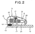
FIG. 2 is a sectional view of a top end stop of the same linear slide fastener; -
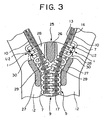
FIG. 3 is a sectional view showing major portions of a normal type linear slide fastener using zigzag-like fastener elements; -
FIG. 4 is a sectional view of a top end stop of the same linear slide fastener; -
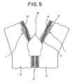
FIG. 5 is a rear view of a hidden type linear slide fastener using coil-like fastener elements; -
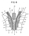
FIG. 6 is a sectional view showing major portions of the same linear slide fastener; -
FIG. 7 is a sectional view of a top end stop of the same linear slide fastener; -
FIG. 8 is a front view showing major portions of a top end stop of a linear slide fastener in which coil-like fastener elements are woven; -
FIG. 9 is a front view showing major portions of a top end stop of a linear slide fastener in which coil-like fastener elements are knit; and -
FIG. 10 is a front view of a top end stop of a well known linear slide fastener. - For a top end stop of a linear slide fastener of the present invention, mono-filaments of synthetic fiber such as polyamide and polyester is formed in a coil-like or zigzag form so as to form linear fastener element rows comprising a plurality of
linear fastener elements 5, and thelinear fastener elements 5 are sewed on the surface on aside edge 13 of afastener tape 12 so as to form anendless fastener chain 9. Aspace portion 10 is produced by removing thelinear fastener elements 5 at an interval corresponding to a predetermined length of the slide fastener in thisfastener chain 9, and the bottom end stop or an opening device is installed at an end of thisspace portion 10 while the top end stop 1 is installed to the other end thereof. Then, the endless fastener chain is cut off at thespace portion 10 so as to complete a normal type slide fastener. - Alternatively, the
linear fastener elements 5 are sewed on abent side edge 14 of thefastener tape 12 bent into the form of letter U so as to form theendless fastener chain 9. By removing thelinear fastener elements 5 of a predetermined interval, thespace portion 10 is formed in thisfastener chain 9 and the bottom end stop and top end stop 1 are installed in thespace portions 10. Then, the fastener chain is cut off at thespace portion 10 so as to complete a hidden type slide fastener. - The several
linear fastener elements 5 adjacent to thespace portion 10 are moved to the inside of thefastener tape 12 from theside edge 13 or thebent side edge 14 of thefastener tape 12 such that they retreat with respect to asewing thread 17. Then, in that retreated condition, the vicinity of thecoupling head 19, for example, its lower side, which makes contact with thefastener tape 12, is fused U1 by ultrasonic processing and fixed so as to form the top end stop 1. Thecoupling head 19 at the top end portion of the coil-like or zigzag-likelinear fastener elements 5 and aninverted portion 20, which is located to the opposite side of thecoupling head 19 or inside of thefastener tape 12 and connected to thecoupling head 19 through aleg portion 21 are moved to the inside of thefastener tape 12 more inwardly compared to the position of other coupling heads 19 andinverted portions 20. Therefore, this top end stop makes contact with an inside wall face 29 of aflange 27 in a mountedslider 25 or afront end portion 30 of theflange 27, thereby stopping the sliding of theslider 25 securely. - Coil-
like fastener elements 6 are produced by winding synthetic fiber mono-filament in the form of a coil as thelinear fastener elements 5 for the linear slide fastener, or alternatively, the mono-filament is bent in a zigzag form so as to form zigzag-like fastener elements 7. - As for the top end stop of the linear slide fastener according to the first embodiment of the invention shown in
FIGS. 1 and2 , the coil-like fastener elements 6 are used as thelinear fastener elements 5, and when the coil-like fastener elements 6 are sewed on the surface of thefastener tape 12 along theside edge 13 with thesewing thread 17, acore thread 16 is passed through the inside of the coil-like fastener elements 6 and this fastener tape is sewed over thecore thread 16 with thesewing thread 17 such that the coupling heads 19 thereof project from theside edge 13 of thefastener tape 12 so as to produce anendless fastener chain 9. - The
space portion 10 is produced at a predetermined interval of thisfastener chain 9 or at every unit length of the slide fastener. By cutting upper andlower leg portions 21 on the side of theinverted portion 20 in the coil-like fastener element 6, thecoupling head 19 is pulled out from thecore thread 16 and thesewing thread 17 so as to produce thespace portion 10. Then, the bottom end stop is created at one end of the formedspace portion 10 while the top end stop 1 is created at the other end thereof, and thereafter, thefastener chain 9 is cut out at thespace portion 10 so as to produce a normal type slide fastener. - By moving the coil-
like fastener elements 6 adjacent to thespace portion 10 formed in thefastener chain 9 to the inside of thefastener tape 12 from theside edge 13 of thefastener tape 12 such that thecoupling head 19 retreats, thecoupling head 19 is made to substantially coincide with theside edge 13. Then, the vicinity of thecoupling head 19 of the coil-like fastener element 6, for example, the lower side thereof, which makes contact with thefastener tape 12, is fused U1 by ultrasonic processing in conditions in which theinverted portion 20 of the coil-like fastener elements 6 retreats from thecore thread 16 and thesewing thread 17 and then, the coil-like fastener elements 6 are fixed to thefastener tape 12. Because theinverted portions 20 of the fixed coil-like fastener elements 6 project to the inside of thefastener tape 12 more inwardly compared to the otherinverted portions 20 of the coil-like fastener elements 6, this portion functions as the top end stop 1. - When the
slider 25 mounted on thefastener chain 9 slides toward the top end of the coil-like fastener elements 6 in order to make engagement of the coil-like fastener elements 6 with each other, as shown inFIG. 1 , this top end stop 1 invades into the inside of theelement passage 28 formed inside theslider 25 through the shoulder side of theslider 25. At this time, the coupling heads 19 at the top end stop 1 just oppose each other without coupling, and theinverted portions 20 at the top end stop 1 come into contact with the inside wall faces 29 of theflange 27 provided on both sides of theelement passage 28 protrudedly. Consequently, the top end stop 1 cannot move toward a rear mouth side of theslider 25 through theelement passage 28, thereby stopping the sliding of theslider 25 easily. Further, by fusing U2 together the overlapping upper andlower leg portions 21 on the side of theinverted portion 20 projected to the inside of thefastener tape 12 with loose spaces by ultrasonic processing, the top end stop 1 can be formed firmly. Depending on the configuration of theslider 25, the top end stop 1 comes into contact with thefront end portion 30 of theflange 27, thereby stopping the sliding of theslider 25 easily. Although the coil-like fastener elements 6 can be sewed only with thesewing thread 17 without making thecore thread 16 pass through the inside of the coil-like fastener elements 6, when moving in the coil-like fastener elements 6, it is necessary to block them from escaping from thesewing thread 17. - For the top end stop of the linear slide fastener of the second embodiment of the invention shown in
FIGS. 3 and4 , the zigzag-like fastener elements 7 are employed as thelinear fastener element 5. In the same manner as in the first embodiment, the zigzag-like fastener elements 7 are sewed on the surface of thefastener tape 12 along theside edge 13 with thesewing thread 17. At this time, the zigzag-like fastener elements 7 are sewed over thecore thread 16 with thesewing thread 17 such that the coupling heads 19 thereof project from theside edge 13 of thefastener tape 12 so as to form anendless fastener chain 9. Thespace portion 10 is produced at a specified interval in thisfastener chain 9. By cutting the upper andlower leg portions 21 on the side of theinverted portion 20 in the zigzag-like fastener elements 7, the coupling heads 19 are pulled out from thecore thread 16 and thesewing thread 17 so as to form thespace portion 10. After the bottom end stop is created at one end of thespace portion 10 and the top end stop 1 is created at the other end thereof, the fastener chain is cut out at thespace portion 10 so as to produce a normal type slide fastener. - By moving several coupling heads 19 of the zigzag-
like fastener elements 7 adjacent to thespace portion 10 formed in thefastener chain 9 to the inside of thefastener tape 12 from theside edge 13 of thefastener tape 12 such that the coupling heads 19 retreat, the coupling heads 19 are made to substantially coincide with theside edge 13. Then, the vicinity of thecoupling head 19 of the zigzag-like fastener element 7, for example, the lower side thereof, which makes contact with thefastener tape 12, is fused U1 by ultrasonic processing in a state in which theinverted portion 20 of the zigzag-like fastener elements 7 retreats from thecore thread 16 and thesewing thread 17, and the zigzag-like fastener elements 7 are fixed to thefastener tape 12. Because theinverted portions 20 of the fixed zigzag-like fastener elements 7 project to the inside of thefastener tape 12 more inwardly compared to the otherinverted portions 20 of the zigzag-like fastener elements 7, this portion functions as the top end stop 1. - When the
slider 25 mounted on thefastener chain 9 slides toward the top end portion of the zigzag-like fastener elements 7 in order to make engagement of the zigzag-like fastener elements 7 with each other, as shown inFIG. 3 , this top end stop 1 invades into the inside of theelement passage 28 formed inside theslider 25 through the shoulder side of theslider 25. At this time, the coupling heads 19 at the top end stop 1 just oppose each other without coupling and theinverted portions 20 at the top end stop 1 come into contact with the inside wall faces 29 of theflange 27 provided on both sides of theelement passage 28 protrudedly. Consequently, the top end stop 1 cannot move toward a rear mouth side of theslider 25 through theelement passage 28, thereby stopping the sliding of theslider 25 easily. Further, by fusing U2 together the upper andlower leg portions 21 on the side of theinverted portion 20 projected to the inside of thefastener tape 12 with loose spaces by ultrasonic processing, the top end stop 1 can be formed firmly. - For the top end stop of the linear slide fastener of the third embodiment shown in
FIGS. 5 and7 , the coil-like fastener elements 6 are employed as thelinear fastener element 5 and the coil-like fastener elements 6 are sewed on the surface of thefastener tape 12 along thebent side edge 14 with thesewing thread 17. At this time, thecore thread 16 is passed through the inside of the coil-like fastener elements 6 and the coil-like fastener elements 6 are sewed over thecore thread 16 with thesewing thread 17 such that the coupling heads 19 thereof project from thebent side edge 14 of thefastener tape 12 so as to form an endless hiddentype fastener chain 9. Thespace portion 10 is produced at a specified interval in thisfastener chain 9. By cutting the upper andlower leg portions 21 on the side of theinverted portion 20 in the coil-like fastener elements 6, the coupling heads 19 are pulled out from thecore thread 16 and thesewing thread 17 so as to form thespace portion 10. After the bottom end stop is created at one end of thespace portion 10 and the top end stop 1 is created at the other end thereof, thefastener chain 9 is cut out at thespace portion 10 so as to produce the hidden type slide fastener. - By moving the coil-
like fastener elements 6 adjacent to thespace portion 10 formed in thefastener chain 9 to the inside of thefastener tape 12 from thebent side edge 14 of thefastener tape 12 such that the coupling heads 19 retreat, the coupling heads 19 are made to substantially coincide with thebent side edge 14. Then, the lower side of thecoupling head 19 in the coil-like fastener element 6, which makes contact with thefastener tape 12, is fused U1 together with thefastener tape 12 by ultrasonic processing in a state in which theinverted portions 20 of the coil-like fastener elements 6 retreat from thecore thread 16 and thesewing thread 17, and the coil-like fastener elements 6 are fixed to thefastener tape 12. Because theinverted portions 20 of the fixed coil-like fastener elements 6 project to the inside of thefastener tape 12 more inwardly compared to the otherinverted portions 20 of the coil-like fastener elements 6, this portion functions as the top end stop 1. - When the
slider 25 mounted on the hiddentype fastener chain 9 slides toward the top end portion of the coil-like fastener elements 6 in order to make engagement of the coil-like fastener elements 6 with each other, as shown inFIG. 6 theinverted portion 20 makes contact with thefront end portion 30 of theflange 27 of theslider 25 because theinverted portion 20 projects to the inside of thefastener tape 12. Consequently, the top end stop 1 cannot invade into the inside of theelement passage 28 of theslider 25, thereby stopping the sliding of theslider 25. According to an alternative way, it is permissible to allow the top end stop 1 to invade into the inside of theelement passage 28 formed inside theslider 25 through the shoulder side while keeping the coupling heads 19 at the top end stop 1 just opposing each other without coupling. At this time, theinverted portions 20 at the top end stop 1 come into contact with the inside wall faces 29 of theflange 27 provided on both sides of theelement passage 28 protrudedly. Consequently, the top end stop 1 cannot move toward a rear mouth side of theslider 25 through theelement passage 28, thereby stopping the sliding of theslider 25. Further, by fusing U2 together the overlapping upper andlower leg portions 21 on the side of theinverted portion 20 projected to the inside of thefastener tape 12 with loose spaces by ultrasonic processing, the top end stop 1 can be formed firmly. - For the top end stop 1 of the linear slide fastener according to the fourth embodiment of the invention shown in
FIG. 8 , the coil-like fastener elements 6 are used as thelinear fastener element 5 and woven into the side end portion of thefastener tape 12 with a needle weaving machine. The coil-like fastener elements 6 are tightened with a plurality ofwarp yarns 32 through theleg portions 21 and theside edge 13 of thefastener tape 12 is woven withweft yarns 33 of double pick while the coupling heads 19 of the coil-like fastener elements 6 project from the side edge. - In the fastener stringer woven in the above-described way, the upper and
lower leg portions 21 exposed on the side of the coupling heads 19 of several elements in the coil-like fastener elements 6 are cut out at a predetermined interval and theelements 6 are pulled out from thewarp yarns 32 through theinverted portion 20 so as to form thespace portion 10, and then, the bottom end stop is created at one end of thisspace portion 10 and the top end stop 1 is created at the other end thereof. Plural pieces of the coupling heads 19 adjacent to thespace portion 10 projecting from theside edge 13 of thefastener tape 12 are moved to the inside of thefastener tape 12, so that theside edge 13 substantially coincide with the front ends of the coupling heads 19 while the coupling heads 19 are kept in a non-coupling condition. Then, theleg portion 21 on the bottom portion of the coil-like fastener element 6 and thefastener tape 12 are fused U1 together so as to prohibit the coupling heads 19 from coupling with other. Theinverted portions 20 overlapping in the vertical direction of the coil-like fastener elements 6 projecting to the inside of thefastener tape 12 in this non-engaging portion are fused U2 together depending on the case, in order to stop the sliding of theslider 25 by bringing theinverted portion 20 into a contact with thefront end portion 30 of theflange 27 of theslider 25 or the inside wall face 29 of theflange 27. Fifth embodiment - For the top end stop 1 of the linear slide fastener according to the fifth embodiment of the invention shown in
FIG. 9 , the coil-like fastener elements 6 are used as thelinear fastener element 5, and the coil-like fastener elements 6 are knit into the side edge portion of the fastener tape with a knitting machine. For thefastener tape 12,chain knitting yarns 34 of 1-0/0-1 and weft in-laidyarns 35 of 3-3/0-0 are disposed on all wales and entangled with each other, and for W1 to W3, weft in-laidyarns 36 of 0-0/2-2 are disposed and entangled with the weft in-laidyarns 35. To knit and fix the coil-like fastener elements 6, theleg portions 21 are captured and tightened with thechain knitting yarns 34 of W2, W3 such that the coupling heads 19 project from thechain knitting yarns 34 on theside edge 13, so as to knit a fastener stringer 11. - In the fastener stringer 11 knit in the above-described way, the upper and
lower leg portions 21 exposed out on the side of the coupling heads 19 of someelements 6 in the coil-like fastener elements 6 are cut out at a predetermined interval and theelements 6 are pulled out from thechain knitting yarns 34 through theinverted portion 20 so as to form thespace portion 10. The bottom end stop is created at one end of thisspace portion 10 and the top end stop 1 is created at the other end. By moving plural coupling heads 19 projecting from theside edge 13 and adjacent to thespace portion 10 to the inside of thefastener tape 12, they are arranged such that theside edge 13 and the front ends of the coupling heads 19 substantially coincide with each other so as to form the non-coupling condition. Theleg portion 21 on the bottom of the coil-like fastener elements 6 in this portion and thefastener tape 12 are fused U1 together and fixed, thereby prohibiting the coupling heads 19 from coupling each other. Theinverted portions 20 overlapping in the vertical direction of the coil-like fastener elements 6 projecting to the inside of thefastener tape 12 in this non-engaging portion are fused U2 together depending on the case, in order to stop the sliding of theslider 25 by bringing theinverted portion 20 into a contact with thefront end portion 30 of theflange 27 of theslider 25 or the inside wall face 29 of theflange 27. Industrial Applicability - The normal type and the hidden type linear slide fastener having the top end stop are applicable as slide fasteners used in an overlapping portion of various kinds of clothes, for example, shirts, sport shirts, sport wears, shirt waist blouses, and jackets. Because the top end stop includes plasticity without any burr on its surface, there is no fear that the skin may be damaged even if it contacts the neck or the like, and further, its tactile feeling is excellent thereby providing no discomfort feeling.
Claims (13)
- A linear slide fastener with a top end stop, the linear slide fastener having a linear fastener element row attached to a side edge (13) of a fastener tape (12) or a bent side edge (14) bent in parallel along the side edge (13), the linear fastener element row comprising a plurality of linear fastener elements (5), characterized in that at least one linear fastener element (5) at a top end portion of the linear fastener element row has been moved to an inside of the fastener tape more inwardly compared to the position of the other linear fastener elements (5),and the moved linear fastener element (5) and the fastener tape (12) has been fused together and fixed so as to form the top end stop (1).
- The linear slide fastener according to claim 1, characterized in that the linear fastener elements (5) comprise a coupling head (19) and an inverted portion (20) connecting adjacent linear fastener elements each other, the inverted portion (20) of the moved linear fastener element (5) is projected to the inside of the fastener tape more inwardly compared to the position of the inverted portions (20) of the other linear fastener elements (5).
- The linear slide fastener according to any preceding claim, characterized in that the linear fastener element (5) which has been moved, fused together and fixed on the fastener tape (12) is adapted to contact with a slider (25) so as to stop the slider (5).
- The linear slide fastener according to any preceding claim, characterized in that the linear fastener element (5) fused together and fixed on the fastener tape (12) has a stop mechanism in which while the right and left coupling heads 19) oppose each other in a non-coupling condition, an inverted portion (20) is adapted to make contact with an inside wall face (29) of a flange (27) of a slider (25).
- The linear slide fastener according to any claim 1 to 3, characterized in that the linear fastener element (5) at a portion where the linear fastener element (5) and the fastener tape (12) are fused together and fixed has a stop mechanism in which while the right and left coupling heads (19) oppose each other in a non-coupling condition, an inverted portion (20) is adapted to make contact with a front end portion (30) of a flange (27) of a slider (25).
- The linear slide fastener according to any preceding claim, characterized in that coil-like fastener elements (6) are used as linear fastener elements (5), and the coil-like fastener elements (6) are attached to a surface of the side edge (13) of the fastener tape (12).
- The linear slide fastener according to any claim 1 to 5, characterized in that zigzag-like fastener elements (7) are used as linear fastener elements (5), and the zigzag-like fastener elements (7) are attached to a surface of the side edge (13) of the fastener tape (12).
- The linear slide fastener according to any claim 1 to 5, characterized in that coil-like fastener elements (6) are used as linear fastener elements (5), and the coil-like fastener elements (6) are sewed on the bent side edge (14) of the fastener tape (12) bent into a form of a letter U along the side edge (13).
- The linear slide fastener according to any preceding claim, characterized in that a core thread (16) is passed through the linear fastener elements (5) and the linear fastener elements (5) are sewed onto the fastener tape (12).
- The linear slide fastener according to any preceding claim, characterized in that the vicinity of a coupling head (19) of said linear fastener element (5) and the fastener tape (12) are fused together and fixed through a contact portion.
- The linear slide fastener according to any claim 1 to 9 characterized in that upper and lower leg portions (21) on a side of an inverted portion (20) of said linear fastener element (5) are fused and fixed to each other.
- The linear slide fastener according to claim 2, characterized in that the linear fastener elements (5) comprise the coupling head (19) projecting from the side edge (13) or the bent side edge (14), and a front end of the coupling head (19) of the moved linear fastener element (5) substantially coincides with the side edge (13) or the bent side edge (14).
- The linear slide fastener according to any preceding claim, characterized in that a plurality of linear fastener elements (5) at the top end portion of the linear fastener element row are moved to the inside of the fastener tape(12).
Applications Claiming Priority (2)
| Application Number | Priority Date | Filing Date | Title |
|---|---|---|---|
| JP2003357949 | 2003-10-17 | ||
| JP2003357949A JP4062617B2 (en) | 2003-10-17 | 2003-10-17 | Top of line slide fastener |
Publications (4)
| Publication Number | Publication Date |
|---|---|
| EP1523900A2 EP1523900A2 (en) | 2005-04-20 |
| EP1523900A3 EP1523900A3 (en) | 2005-12-21 |
| EP1523900B1 true EP1523900B1 (en) | 2008-04-09 |
| EP1523900B8 EP1523900B8 (en) | 2008-07-09 |
Family
ID=34373632
Family Applications (1)
| Application Number | Title | Priority Date | Filing Date |
|---|---|---|---|
| EP04022950A Expired - Lifetime EP1523900B8 (en) | 2003-10-17 | 2004-09-27 | Linear slide fastener with top end stop |
Country Status (8)
| Country | Link |
|---|---|
| US (1) | US7137177B2 (en) |
| EP (1) | EP1523900B8 (en) |
| JP (1) | JP4062617B2 (en) |
| KR (1) | KR100563204B1 (en) |
| CN (1) | CN100334983C (en) |
| DE (1) | DE602004012941T2 (en) |
| ES (1) | ES2303010T3 (en) |
| TW (1) | TWI241897B (en) |
Families Citing this family (15)
| Publication number | Priority date | Publication date | Assignee | Title |
|---|---|---|---|---|
| US8397353B2 (en) * | 2008-11-26 | 2013-03-19 | Chao-Mu Chou | Continuous-coil type waterproof slide fastener and the structure impervious to fluid thereof |
| WO2011004462A1 (en) * | 2009-07-07 | 2011-01-13 | Ykk株式会社 | Slide fastener |
| CN102665476B (en) * | 2009-12-14 | 2015-05-13 | Ykk株式会社 | Slide fastener |
| US8484764B2 (en) | 2010-08-18 | 2013-07-16 | Under Armour, Inc. | Zipper arrangement |
| US8528115B2 (en) | 2010-11-16 | 2013-09-10 | Under Armour, Inc. | Zipper arrangement with foldable pull |
| US8484811B2 (en) | 2010-11-16 | 2013-07-16 | Under Armour, Inc. | Zipper arrangement with wheeled slider |
| US8341809B2 (en) | 2010-11-16 | 2013-01-01 | Under Armour, Inc. | Zipper arrangement with funnel grip |
| US8707524B2 (en) * | 2011-11-01 | 2014-04-29 | Lien-Chou Wang | Double sided nylon sandwich mesh fabric zipper and slider assembly |
| US10575601B2 (en) | 2015-10-02 | 2020-03-03 | Under Armour, Inc. | Stop for zipper arrangement |
| CN205358475U (en) * | 2016-02-05 | 2016-07-06 | 理想(广东)拉链实业有限公司 | Single face top zipper stop |
| CN106923453A (en) * | 2017-05-12 | 2017-07-07 | 浙江伟星实业发展股份有限公司 | A kind of slide fastener and commodity |
| CN107640097A (en) * | 2017-11-02 | 2018-01-30 | 昆山誉球模塑有限公司 | A kind of foldable recyclable article shading curtain |
| JP2023503233A (en) | 2019-11-23 | 2023-01-27 | タロン テクノロジーズ、インコーポレイティッド | curved zipper |
| US11363860B2 (en) | 2019-11-23 | 2022-06-21 | Talon Technologies, Inc. | Waterproof curved zippers |
| CN114801355B (en) * | 2022-04-11 | 2023-12-15 | 武汉纺织大学 | High-composite-strength multilayer heat insulation material and application thereof |
Family Cites Families (9)
| Publication number | Priority date | Publication date | Assignee | Title |
|---|---|---|---|---|
| GB1000597A (en) * | 1963-02-19 | 1965-08-04 | Lightning Fasteners Ltd | Sliding clasp fasteners |
| CA980987A (en) * | 1970-08-17 | 1976-01-06 | George B. Moertel | Slide fastener chains |
| DE7214882U (en) * | 1971-04-20 | 1972-08-24 | Yoshida K | Zipper |
| JP2597490Y2 (en) * | 1992-07-16 | 1999-07-05 | ワイケイケイ株式会社 | Stop of hidden slide fastener |
| JP3620973B2 (en) * | 1998-09-30 | 2005-02-16 | Ykk株式会社 | Slide fastener fastener |
| JP3621014B2 (en) * | 1999-04-22 | 2005-02-16 | Ykk株式会社 | Chain for slide fastener, terminal molding method and terminal molding apparatus |
| JP3621040B2 (en) * | 2000-10-31 | 2005-02-16 | Ykk株式会社 | Reverse opening and closing insert for slide fastener |
| JP4116827B2 (en) * | 2002-06-20 | 2008-07-09 | Ykk株式会社 | Slide fastener stop |
| KR100571970B1 (en) * | 2003-12-19 | 2006-04-18 | 와이케이케이 가부시끼가이샤 | End stop for slide fastener |
-
2003
- 2003-10-17 JP JP2003357949A patent/JP4062617B2/en not_active Expired - Fee Related
-
2004
- 2004-09-16 TW TW093128035A patent/TWI241897B/en not_active IP Right Cessation
- 2004-09-27 EP EP04022950A patent/EP1523900B8/en not_active Expired - Lifetime
- 2004-09-27 ES ES04022950T patent/ES2303010T3/en not_active Expired - Lifetime
- 2004-09-27 DE DE602004012941T patent/DE602004012941T2/en not_active Expired - Lifetime
- 2004-10-13 KR KR1020040081633A patent/KR100563204B1/en not_active Expired - Fee Related
- 2004-10-14 US US10/966,324 patent/US7137177B2/en not_active Expired - Fee Related
- 2004-10-15 CN CNB2004100841766A patent/CN100334983C/en not_active Expired - Lifetime
Also Published As
| Publication number | Publication date |
|---|---|
| ES2303010T3 (en) | 2008-08-01 |
| CN1608537A (en) | 2005-04-27 |
| HK1071986A1 (en) | 2005-08-12 |
| DE602004012941T2 (en) | 2009-05-28 |
| TWI241897B (en) | 2005-10-21 |
| CN100334983C (en) | 2007-09-05 |
| EP1523900A3 (en) | 2005-12-21 |
| KR100563204B1 (en) | 2006-03-22 |
| US7137177B2 (en) | 2006-11-21 |
| US20050081340A1 (en) | 2005-04-21 |
| DE602004012941D1 (en) | 2008-05-21 |
| JP2005118359A (en) | 2005-05-12 |
| KR20050037354A (en) | 2005-04-21 |
| JP4062617B2 (en) | 2008-03-19 |
| EP1523900B8 (en) | 2008-07-09 |
| TW200514526A (en) | 2005-05-01 |
| EP1523900A2 (en) | 2005-04-20 |
Similar Documents
| Publication | Publication Date | Title |
|---|---|---|
| EP1523900B1 (en) | Top end stop of linear slide fastener | |
| US11206901B2 (en) | Slide fastener-attached product, element member and manufacturing method of slide fastener-attached product | |
| EP1938706B1 (en) | Slide fastener with top end stop | |
| US20150366300A1 (en) | Stringers Without Fastener Tape and Article with Slide Fastener | |
| EP1537801B1 (en) | Method of making a slide fastener | |
| EP1702529B1 (en) | Linear slide fastener | |
| EP1072209B1 (en) | Linear slide fastener | |
| CN109475207B (en) | Braided zipper chain | |
| EP0698353B1 (en) | Warp-knit tape for slide fastener | |
| US12022920B2 (en) | Element member and slide fastener-attached product | |
| US20020184741A1 (en) | Knit-in slide fastener | |
| US4099302A (en) | Slide fastener | |
| CN108158140B (en) | Product with slide fastener, element member, and method for manufacturing product with slide fastener | |
| EP1444914B1 (en) | Slide fastener | |
| EP0216383B1 (en) | Slide fastener stringer | |
| WO2022168239A1 (en) | Fastener stringer and method for manufacturing same | |
| CN120477459A (en) | Concealed slide fastener | |
| JP2025124267A (en) | Zipper Stringer | |
| CN120284049A (en) | Chain parts for zippers and products with zippers | |
| HK1071986B (en) | Top end stop of linear slide fastener | |
| HK1076587B (en) | Stop section for slide fastener, and slide fastener having such stop section | |
| HK1091106B (en) | Linear slide fastener | |
| HK1086458A1 (en) | Braiding/weaving concealed slide fastener | |
| HK1081086A1 (en) | Opener for slide fastener | |
| HK1081086B (en) | Opener for slide fastener |
Legal Events
| Date | Code | Title | Description |
|---|---|---|---|
| PUAI | Public reference made under article 153(3) epc to a published international application that has entered the european phase |
Free format text: ORIGINAL CODE: 0009012 |
|
| AK | Designated contracting states |
Kind code of ref document: A2 Designated state(s): AT BE BG CH CY CZ DE DK EE ES FI FR GB GR HU IE IT LI LU MC NL PL PT RO SE SI SK TR |
|
| AX | Request for extension of the european patent |
Extension state: AL HR LT LV MK |
|
| PUAL | Search report despatched |
Free format text: ORIGINAL CODE: 0009013 |
|
| AK | Designated contracting states |
Kind code of ref document: A3 Designated state(s): AT BE BG CH CY CZ DE DK EE ES FI FR GB GR HU IE IT LI LU MC NL PL PT RO SE SI SK TR |
|
| AX | Request for extension of the european patent |
Extension state: AL HR LT LV MK |
|
| 17P | Request for examination filed |
Effective date: 20060405 |
|
| AKX | Designation fees paid |
Designated state(s): DE ES FR GB IT TR |
|
| 17Q | First examination report despatched |
Effective date: 20070423 |
|
| GRAP | Despatch of communication of intention to grant a patent |
Free format text: ORIGINAL CODE: EPIDOSNIGR1 |
|
| GRAS | Grant fee paid |
Free format text: ORIGINAL CODE: EPIDOSNIGR3 |
|
| GRAA | (expected) grant |
Free format text: ORIGINAL CODE: 0009210 |
|
| AK | Designated contracting states |
Kind code of ref document: B1 Designated state(s): DE ES FR GB IT TR |
|
| REG | Reference to a national code |
Ref country code: GB Ref legal event code: FG4D |
|
| REF | Corresponds to: |
Ref document number: 602004012941 Country of ref document: DE Date of ref document: 20080521 Kind code of ref document: P |
|
| RTI2 | Title (correction) |
Free format text: LINEAR SLIDE FASTENER WITH TOP END STOP |
|
| REG | Reference to a national code |
Ref country code: ES Ref legal event code: FG2A Ref document number: 2303010 Country of ref document: ES Kind code of ref document: T3 |
|
| EN | Fr: translation not filed | ||
| PLBE | No opposition filed within time limit |
Free format text: ORIGINAL CODE: 0009261 |
|
| STAA | Information on the status of an ep patent application or granted ep patent |
Free format text: STATUS: NO OPPOSITION FILED WITHIN TIME LIMIT |
|
| ET | Fr: translation filed | ||
| REG | Reference to a national code |
Ref country code: FR Ref legal event code: EERR Free format text: CORRECTION DE BOPI 09/05 - BREVETS EUROPEENS DONT LA TRADUCTION N A PAS ETE REMISE A L INPI. IL Y A LIEU DE SUPPRIMER : LA MENTION DE LA NON-REMISE. LA REMISE DE LA TRADUCTION EST PUBLIEE DANS LE PRESENT BOPI. |
|
| 26N | No opposition filed |
Effective date: 20090112 |
|
| PGFP | Annual fee paid to national office [announced via postgrant information from national office to epo] |
Ref country code: DE Payment date: 20140923 Year of fee payment: 11 |
|
| PGFP | Annual fee paid to national office [announced via postgrant information from national office to epo] |
Ref country code: ES Payment date: 20140812 Year of fee payment: 11 Ref country code: GB Payment date: 20140924 Year of fee payment: 11 |
|
| PGFP | Annual fee paid to national office [announced via postgrant information from national office to epo] |
Ref country code: IT Payment date: 20140919 Year of fee payment: 11 |
|
| PGFP | Annual fee paid to national office [announced via postgrant information from national office to epo] |
Ref country code: FR Payment date: 20140906 Year of fee payment: 11 |
|
| REG | Reference to a national code |
Ref country code: DE Ref legal event code: R119 Ref document number: 602004012941 Country of ref document: DE |
|
| PG25 | Lapsed in a contracting state [announced via postgrant information from national office to epo] |
Ref country code: IT Free format text: LAPSE BECAUSE OF NON-PAYMENT OF DUE FEES Effective date: 20150927 |
|
| GBPC | Gb: european patent ceased through non-payment of renewal fee |
Effective date: 20150927 |
|
| REG | Reference to a national code |
Ref country code: FR Ref legal event code: ST Effective date: 20160531 |
|
| PG25 | Lapsed in a contracting state [announced via postgrant information from national office to epo] |
Ref country code: DE Free format text: LAPSE BECAUSE OF NON-PAYMENT OF DUE FEES Effective date: 20160401 Ref country code: GB Free format text: LAPSE BECAUSE OF NON-PAYMENT OF DUE FEES Effective date: 20150927 |
|
| PG25 | Lapsed in a contracting state [announced via postgrant information from national office to epo] |
Ref country code: FR Free format text: LAPSE BECAUSE OF NON-PAYMENT OF DUE FEES Effective date: 20150930 |
|
| REG | Reference to a national code |
Ref country code: ES Ref legal event code: FD2A Effective date: 20161028 |
|
| PG25 | Lapsed in a contracting state [announced via postgrant information from national office to epo] |
Ref country code: ES Free format text: LAPSE BECAUSE OF NON-PAYMENT OF DUE FEES Effective date: 20150928 |
|
| PGFP | Annual fee paid to national office [announced via postgrant information from national office to epo] |
Ref country code: TR Payment date: 20210924 Year of fee payment: 18 |
|
| PG25 | Lapsed in a contracting state [announced via postgrant information from national office to epo] |
Ref country code: TR Free format text: LAPSE BECAUSE OF NON-PAYMENT OF DUE FEES Effective date: 20220927 |